


TDS 190
Instruction Manual
αlpha TDS 190
1/8 DIN Total Dissolved Solids Controller
with Temperature display and Transmitter
68X276108
Rev 0 11/2004
Technolo
g
y
M
ade
E
a
s
y
.
.
.

PREFACE
This manual serves to explain the use of the αlpha TDS 190 controller/transmitter.
This manual functions in two ways: first, as a step-by-step guide to help you
operate the meter; second, it serves as a handy reference guide.
This manual is written to cover as many anticipated applications of the αlpha TDS
190 controller/transmitter as possible. If there are doubts in the use of the αlpha
TDS 190 controller / transmitter, do not hesitate to contact the nearest Eutech
Instruments Authorized Distributor.
Eutech Instruments cannot accept any responsibility for damage or malfunction to
the controller/transmitter caused by improper use of the instrument. Remember to
fill in the guarantee card and mail it to your Authorized Distributor or Eutech
Instruments Pte Ltd.
The information presented in this manual is subject to change without notice as
improvements are made, and does not represent a commitment on the part of
Eutech Instruments Pte Ltd.
Copyright
©
2004
All rights reserved.
Rev. 0 11/2004
Eutech Instruments Pte Ltd.

TABLE OF CONTENTS
1 INTRODUCTION 1
2 SAFETY INFORMATION 2
3 OVERVIEW 3
3.1 FRONT PANEL 3
3.2 BACK PANEL 4
3.3 WIRING 5
3.4 PANEL-MOUNTING THE CONTROLLER 5
3.5 FERRITE ASSEMBLY 6
4 MEASUREMENT MODE 7
4.1 MEASUREMENT MODE DISPLAY 7
4.2 SET POINTS ADJUSTMENTS 8
5 PASSWORD 9
6 TDS CALIBRATION 11
7 TEMPERATURE CALIBRATION 13
8 SETUP MODE 14
8.1 GENERAL INFORMATION 14
8.2 SETUP MODE OVERVIEW 15
8.3 SET POINT 1 – P1.0 16
8.4 SET POINT 2 – P2.0 18
8.5 MEASUREMENT RANGE SELECTION – P3.0 20
8.6 CONFIGURE TEMPERATURE SETTINGS – P4.0 21
8.7 VIEWING TDS CALIBRATION DATA – P5.0 22
8.8 VIEWING TDS/ TEMPERATURE ELECTRODE DATA – P6.0 23
8.9 SETTING TDS FACTOR – P7.0 24
8.10 CONTROLLER RESET – P8.0 25
9 RELAYS 26
10 TRANSMITTER FUNCTION 26
11 SPECIFICATIONS 27
12 ACCESSORIES 28
13 GENERAL INFORMATION 31

1
1 INTRODUCTION
Thank you for purchasing the αlpha TDS 190 ⅛ DIN TDS Controller. This
controller is part of a series of quality process controllers available from Eutech
Instruments. These sturdy, economical TDS controllers are designed with the
features and reliability of a much more expensive instrument.
Your controller includes:
• Removable terminal blocks for easy connections;
• Two mounting brackets for easy panel mounting;
Some features of this controller are:
• Two set point, two SPDT relay operation
• Scrolling, 14-segment LED guides user easily through setup functions
• Reliable power supply from 85 to 260 V AC, 50/60 Hz or DC withstands
voltage fluctuations
• Push-button operation from the front panel
• Single-point calibration for each individual range
• Adjustable hysteresis band prevents rapid contact switching around set-point
• Selectable automatic or manual temperature compensation
• Two-level password protection
• Removable terminal strips for quick and easy connections
• Built-in non volatile memory backup retains setup even if power fails,
and lets you configure unit before installation
• Isolated 4-20 mA output for remote monitoring or hard copy recording
2
2 SAFETY INFORMATION
The Eutech Controller / Transmitter shall be installed and operated only in the
manner specified in the Instruction manual. Only skilled, trained or authorized
person should carry out installation, setup and operation of the instrument.
Before powering up the unit, make sure that power source it is connected to, is as
specified in the top label. Failure to do so may result in a permanent damage to the
unit.
The unit has live and exposed parts inside. If it has to be opened, make sure that
the power to the unit is off and disconnected.
The unit is Fuse protected. In the event the fuse has to be replaced, use only those
as specified in the manual.
The degree of protection against electric shock will be achieved only by
observance of the corresponding installation rules.
3
3 OVERVIEW
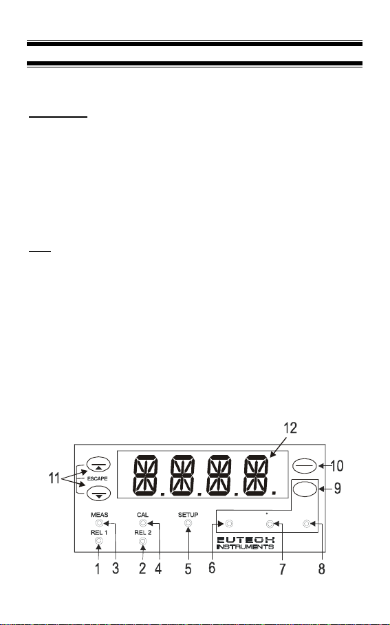
3.1 Front Panel
The front panel consists of a 4-digit LED display, 8 LED annunciators and 4 keys.
Annunciators
1. REL 1 Displayed when Relay 1 is activated
2. REL 2 Displayed when Relay 2 is activated
3. MEAS Displayed in measurement mode
4. CAL Displayed in calibration mode
5. SETUP Displayed in setup mode
6. ppm Unit of the displayed parameter (parts per million)
7.
o
C Unit of the displayed parameter (temperature)
8. ppt Unit of the displayed parameter (parts per thousand)
Keys
9. MODE Use to toggle between Measurement modes
(TDS and temperature).
10. CAL / ENTER Use to enter Calibration mode.
Use also to enter into levels of the Setup mode
and to confirm changes made.
11. SP1 / ▲
SP2 / ▼
Use to enter Set Point 1 (SP1) or Set Point 2
(SP2) adjustment mode.
Use as increment or decrement keys during
Calibration and Setup modes.
Use both keys together in Calibration and Setup
modes to escape to Measurement mode.
12.14-segment display
CAL
ENTER
MODE
TDS 190 Series
ppm
ppt
SP1
SP2
C
4
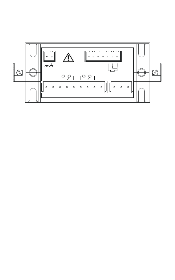
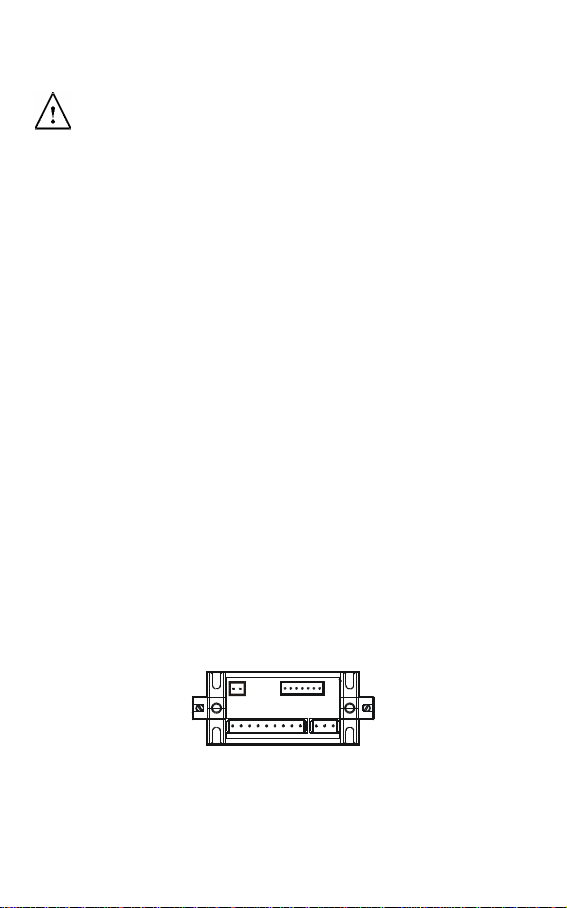
3.2 Back Panel
The back panel consists of three different connectors that can be used with
removable terminal blocks (included):
12 11 10 9
1820 1921
8
17
7
16
6
15
35
14
24
13
S
E
N
S
E
PT100
RELAY2
NC NC N L
-
4
-
2
0
m
A
+
4
-
2
0
m
A
RELAY1
Caution
I
N
G
N
D
+
C
O
N
-
C
O
N
N
C
N
C
1
1. VAC live wire
2. VAC neutral wire
3. unused
4. unused
5. Relay 2 deactivated position (normally closed)
6. Relay 2 center pole
7. Relay 2 activated position (normally open)
8. Relay 1 deactivated position (normally closed)
9. Relay 1 center pole
10. Relay 1 activated position (normally open)
11. 4-20 mA connection, negative
12. 4-20 mA connection, positive
13.
Pt 100 connection: sense (jumper to terminal 14 if using 2-wire RTD)
14. Pt 100 connection: input
15. Pt 100 connection: ground
16. Conductivity positive terminal
17. Conductivity negative terminal
18. unused
19. unused
20. VAC protective ground wire
21. VAC protective ground wire
5
3.3 Wiring
Caution: Ensure electrical mains are disconnected before proceeding.
1. Connect the power supply to the three-pin terminal block
• VAC live wire = 1
• VAC neutral wire = 2
• VAC protective ground wire = 20 OR 21
αlpha TDS 190 controller accepts voltages from 85 to 260 VAC, 50/60 Hz or DC.
2. Connect the Pt 100 leads to terminals 13 to 15 of the seven-pin terminal block.
Either wire can be connected to either terminal. Terminals 13 and 14 must be
shunted unless using a 3-wire RTD.
NOTE: αlpha TDS 190 is factory set for Automatic temperature compensation.
MTC can be selected in Program P4.0.
3. Power on the controller. The display automatically shows the TDS reading, the
ppm and ‘MEAS’ annunciators’ lights.
NOTE: In the event Pt 100 is not connected or the connection is broken in the ATC
mode, the display flashes ‘OR’ to alert you.
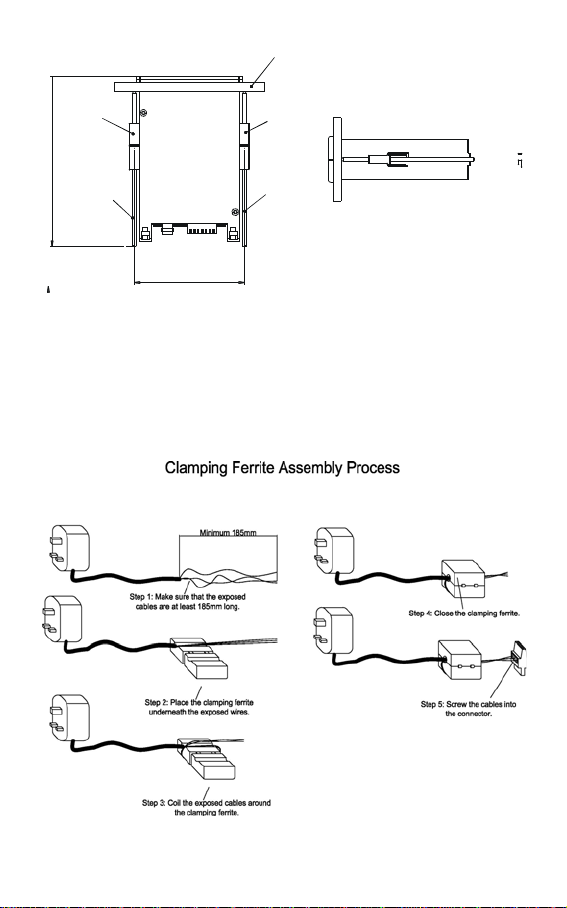
3.4 Panel-mounting the controller
The supplied mounting hardware allows surface mounting to all panels and
protective enclosures. Mounting cut-out size is 91 x 45 mm.
To attach the mounting to the controller:
1. Align the catch to the side of the controller, and insert threaded rods through
catch.
12 11 10 9 8 7 6 5 4 3 2 1
19 18 17 16 15 1 4 1321 20
2. Screw the threaded-rod through the catch in a clock-wise direction. Tighten
until the catch holds the controller firmly against the back of the panel or
protective housing. Repeat on the other side.
6
SIDE VIEW
approx.
100
Wall panel
Catch
Threaded rod
Catch
Threaded rod
TOP VI EW
a
p
p
r
o
x
.
1
5
4
.
2
0
3.5 Ferrite Assembly
The power cable (L, N & E) needs to be connected to the instrument with two turns
through the Split Ferrite which is supplied as an accessory with the instrument. It is
strongly suggested that the Ferrite element supplied as a standard accessory be
installed as described below.
7
4 MEASUREMENT MODE
The αlpha TDS 190 controller is capable of taking TDS measurement with
Automatic (ATC) or Manual (MTC) Temperature Compensation.
The measurements are displayed distinguishingly by the annunciators on the front
panel.
4.1 Measurement mode display
Press the MODE key to toggle between TDS and Temperature measurement
mode.
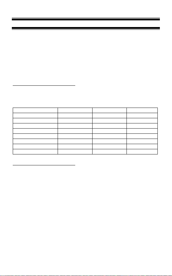
Conductivity Measurement Mode
The controller displays the selected TDS range number, R X (X ranges from 1 to
8), for 2 seconds before displaying the TDS measurement. The
ppm or ppt
annunciator will light up depending on which range is selected.
TDS Range Range No., R Resolution Cell Constant
0.00 – 10.00 ppm 1 0.01 ppm 0.1
0.0 – 100.0 ppm 2 0.1 ppm 0.1
0.0 – 100.0 ppm 3 0.1 ppm 1
0 – 1000 ppm 4 1 ppm 1
0.00 – 5.00 ppt 5 0.01 ppt 1
0.00 – 10.00 ppt 6 0.01 ppt 1
0.0 – 100.0 ppt 7 0. 1 ppt 1
0.0 – 100.0 ppt 8 0.1 ppt 10
Temperature Measurement mode
Press MODE key once to view the temperature measurement. The °C annunciator
lights up. The display shows ATC or MTC, then the current measured temperature.
For selection of temperature compensation ATC or MTC, see Setup program P4.1.
NOTE: After pressing the MODE key to display Temperature, if there is no further
key-press, the Controller will automatically revert to TDS Measurement mode after
about 30 seconds.

8
4.2 Set Points Adjustments
You can make quick set points adjustments with the direct access of the Set Points
adjustment modes (SP1 and/or SP2). By just pressing the SP1/▲ or SP2/▼key,
you can enter the Set Point adjustment mode and set a new TDS value that will
cause your controller to activate.
Set Point 1 (SP1) adjustment mode
This lets you adjust the TDS value in Set Point 1. If this value is crossed, the set
point relay 1 LED will light.
1. Press the SP1/▲ key. The screen will scroll P1.1, SP1, and then the current
set point value.
2. Press the ▲ or ▼ keys and adjust first relay set point. Default value is 10%
of full scale of range selected.
3. Press ENTER to confirm and return to the measurement mode.
NOTE: Press ▲ and ▼ keys together (ESCAPE) at anytime, to return to
Measurement mode.
Set Point 2 (SP2) adjustment mode
This lets you adjust the TDS value in Set Point 2. If this value is crossed, the set
point relay 2 LED will light.
4. Press the SP2/▲ key. The screen will scroll P2.1, SP2, and then the current
set point value.
5. Press the ▲ or ▼ keys and adjust first relay set point. Default value is 90%
of full scale of range selected.
6. Press ENTER to confirm and return to the measurement mode.
NOTE: Press ▲ and ▼ keys together (ESCAPE) at anytime, to return to
Measurement mode.
NOTE: These modes are only for adjusting relay 1 and/or relay 2 set points values.
To set the relays as low or high set points or to set its hysteresis values, you have
to make the adjustments from the Setup mode as in Section 8.3 and Section 8.4.
 Loading...