


EUTECH INSTRUMENTS
α lpha-pH800
pH and ORP Controller/Transmitter
Operating Instructions
68X216813
03/99
Preface
Thank you for purchasing the α lpha-pH800 series pH/ORP controller/transmitter.
This manual serves to explain the use of the α lpha-pH800 series pH/ORP controller/transmitter. The manual functions in two ways, firstly as a step by step guide to help the user operate the instrument. Secondly, it serves as a handy reference guide. This instruction manual is written to cover as many anticipated applications of the α lpha-pH800 pH/ORP controller/transmitter. If you have doubts in the use of the instrument, please do not hesitate to contact the nearest Eutech Instruments’ Authorised Distributor.
The information presented in this manual is subject to change without notice as improvements are made, and does not represent a commitment on part of Eutech Instruments Pte Ltd.
Eutech Instruments cannot accept any responsibility for damage or malfunction of the unit due to improper use of the instrument.
Copyright 1999 Eutech Instruments Pte Ltd. Version 1.0. All rights reserved.
Eutech Instruments Pte Ltd. Blk 55, Ayer Rajah Crescent #04-14/24, Singapore 139 949. Tel: (65) 778 6876; Fax: (65) 773 0836; e-mail: marketing@eutechinst.com; Home page: http://www.eutechinst.com
TABLE OF CONTENTS
1 |
INTRODUCTION................................................................................................ |
1 |
|
|
1.1 |
Description of Unit.................................................................................... |
1 |
|
1.2 |
Applications................................................................................................ |
2 |
2 |
ASSEMBLY AND INSTALLATIONS............................................................. |
3 |
|
|
2.1 |
Measurement and Control System........................................................ |
3 |
|
2.2 |
Unit Dimensions ....................................................................................... |
3 |
3 |
ELECTRICAL CONNECTIONS....................................................................... |
4 |
|
|
3.1 |
Connection Diagram................................................................................ |
4 |
|
3.2 |
Back Panel................................................................................................ |
6 |
4 |
OVERVIEW....................................................................................................... |
8 |
|
|
4.1 |
Keypad and Display................................................................................. |
8 |
|
Function Groups................................................................................................... |
9 |
|
|
4.2 |
Control Concept ....................................................................................... |
9 |
5 |
MEASUREMENT............................................................................................ |
10 |
|
|
5.1 |
Display in Measurement mode ............................................................ |
10 |
6 |
CALIBRATION............................................................................................... |
11 |
|
|
6.1 |
pH Calibration......................................................................................... |
11 |
|
6.2 |
ORP – mV Calibration........................................................................... |
13 |
7 |
ADVANCED SET UP MODE......................................................................... |
14 |
|
|
7.1 |
Electrode Offset (OFS) sub-function................................................... |
14 |
|
7.2 |
Setting temperature (Set oC) sub-function ......................................... |
15 |
|
7.3 |
Control Relay A/Control Relay B (SP1/SP2) sub-function............... |
18 |
|
7.4 |
Configuration (ConF) sub-function ...................................................... |
22 |
|
7.5 |
Calibration (CAL) sub-function............................................................. |
23 |
8 |
TECHNICAL SPECIFICATIONS................................................................... |
24 |
|
9 |
ACCESSORIES ............................................................................................... |
25 |
|
10 |
|
GENERAL INFORMATION....................................................................... |
25 |
|
10.1 |
Warranty.................................................................................................. |
25 |
|
10.2 |
Packaging ............................................................................................... |
25 |
|
10.3 |
Return of Goods..................................................................................... |
26 |
|
10.4 |
Guidelines for Returning Unit for Repair ............................................ |
26 |
11 |
|
APPENDICES.............................................................................................. |
27 |
|
11.1 |
Appendix 1 .............................................................................................. |
27 |
|
11.2 |
Appendix 2 .............................................................................................. |
28 |
|
11.3 |
Appendix 3 .............................................................................................. |
29 |
1 INTRODUCTION
1.1Description of Unit
Thank you for purchasing Eutech’s ¼ DIN alpha-800 series pH/ORP process controllers. This unit is used for measuring either pH or ORP parameter one at a time, and the operational mode is switchable from the menu. You can use this unit to measure pH or ORP with limit control. This controller has many user-friendly and safety features which include:
•Menu-driven program that simplifies set-up
•Built-in non-volatile memory backup to ensure that calibration and other information are not erased if power supply fails
•Push-button two-point calibration and electrode offset adjustment from the keypad
•Automatic temperature compensation (ATC)
•Manual temperature compensation setting without the ATC probe, with independent setting for calibration and process temperature
•0 to 2000 second time delay adjustment on all relays – minimise false alarms
•Separately adjustable high and low set point hysteresis (dead bands) prevent chattering of relays around the set points
•Asymmetrical/symmetrical input for pH/ORP operation
•Large dual display LCD for easy reading with clear multiple annunciators, alarm status, operational and error messages
•Two switching contacts as set-point triggering relays
•Hold function freezes output current (4/20mA) and control relays
•LED indicators signal control activities to monitor controller status from a distance
•Protection against electromagnetic interference – Input and output are free from external inference
1
1.2Applications
Use this controller in panel mounted enclosures for applications such as water treatment and monitoring, galvanic-decontamination, chemical processing food processing, clean or waste water control and neutralisation process.
2
2 ASSEMBLY AND INSTALLATIONS
2.1Measurement and Control System
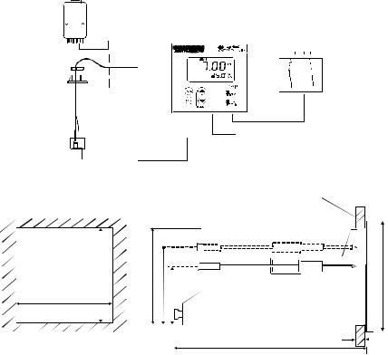
A typical measurement system consists of:
•a pH/ORP process controller
•a pH/ORP combination electrode with integrated or separate temperature sensor Pt 100/1000,
•an immersion, flow or process assembly with or without a potential matching pin (PMP)
•a final control element such as pump or valve
•a recorder
Flow Assembly
pH Controller
Chart Recorder
Process Assembly |
|
with Electrode |
Measurement Cable |
Power Mains
(220/110 VAC)
2.2Unit Dimensions
|
Flat Gasket (1mm) |
||||||
|
(To be Inserted By Customer) |
||||||
92 + 0.5 |
Note: The Taped Corners Have to Be On Top |
|
|
||||
|
|||||||
|
|
|
|
|
|
|
|
|
|
|
|
|
|
|
|
|
|
|
|
|
|
|
|
|
|
|
|
|
|
|
|
|
|
|
|
|
|
|
|
|
|
|
|
|
|
|
|
|
|
|
|
|
|
|
|
|
|
|
|
|
|
|
|
|
|
|
|
|
|
|
|
|
|
|
|
|
|
|
|
|
|
|
|
96 |
|||
|
|
|
|
||||
92 |
56 |
|
|
|
|||
|
|
|
|||||
|
|
|
|
|
|
|
|
|
|
|
|
|
|
|
|
92 + 0.5 |
32 |
|
|
|
|
|
|
|
|
|
|
||||
|
|
|
|
|
|
|
|
|
|
|
|
|
|
||
|
|
|
|
|
|
|
|
|
|
|
|
|
|
|
|
|
|
|
|
|
|
||
|
|
|
|
|
|
|
|
|
|
max. 45 |
|||||
Mounting Cut-Out |
max. 175 |
||||||
The field-tested control panel housing is 96 x 96 mm; with protection class IP 54 (front).
3
3 ELECTRICAL CONNECTIONS
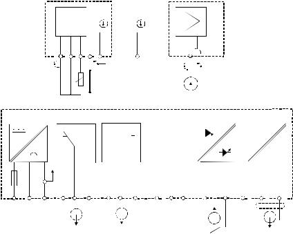
3.1Connection Diagram
|
|
|
|
|
|
|
|
|
|
|
|
|
|
|
|
|
|
|
|
|
|
|
|
|
|
|
|
|
|
|
|
|
|
|
|
|
pH |
|
|
|
|
|||||
|
|
|
|
|
|
|
|
|
|
|
|
|
|
|
|
|
V |
|
|
|
|
|
S/ |
|
S/ |
|
|
|
|
|
|
|
|
|
|
|
|
|
|
|
|
|
||||
|
|
|
|
|
|
|
|
|
|
|
|
|
|
|
|
|
|
|
|
|
|
|
|
|
|
|
|
|
|
|
|
|
|
|
|
|
|
|
|
|
|
|
|
|||
|
|
|
18 |
19 |
|
|
|
20 |
|
|
21 |
|
22 |
|
|
|
|
|
|
|
|
|
|
|
|
|
BNC |
|
|
|
|
|||||||||||||||
|
|
|
|
|
|
|
|
|
|
|
|
|
|
|
|
|
|
|
|
|
|
|
|
|
|
|
|
PE/S |
|
|
|
|
|
|
|
|
|
|
|
|
|
|
|
|
|
|
|
|
|
|
|
|
|
|
|
|
|
|
|
|
|
|
|
|
|
|
|
|
|
|
|
|
|
|
|
|
|
|
|
|
|
|
|
|
|
|
|
|
|
|
|
|
|
|
|
|
|
|
|
|
|
|
|
|
|
|
|
|
|
|
|
|
|
|
|
|
|
|
|
|
|
|
|
|
|
|
|
|
|
|
|
|
|
|
|
|
|
|
|
|
|
|
|
|
|
|
|
|
|
|
|
|
|
|
|
|
|
|
|
|
|
|
|
|
|
|
|
|
|
|
|
|
|
|
|
|
|
|
|
|
|
|
|
|
|
|
|
|
|
|
|
|
|
|
|
|
|
|
|
|
|
|
|
|
|
|
|
|
|
|
|
|
|
|
|
|
|
|
|
|
|
|
|
|
|
|
|
|
|
|||||
|
|
|
|
|
Pt 100 |
|
|
|
|
|
|
|
Potential Matching Pin (PMP) |
|
Signal Input pH/ORP |
|
|
|
|
|||||||||||||||||||||||||||
Power Mains |
|
|
|
|
|
|
Relay A |
|
|
|
Relay B |
|
|
|
|
|
|
|
|
|
|
|
Hold Input |
|
Signal Output |
|
||||||||||||||||||||
|
|
|
|
|
|
|
|
|
|
|
|
|
|
|
|
|
|
|
|
|
|
|
|
|
|
|
|
|
|
|
|
|
|
|
|
|
|
|
|
|
|
|
|
pH |
mA |
|
|
|
|
|
|
|
|
|
|
|
|
|
|
|
|
|
|
|
|
|
|
|
|
|
|
|
|
|
|
|
|
|
|
|
|
|
|
|
|
|
|
|
|
|
|
||
|
|
|
|
|
|
|
|
|
|
|
|
|
|
|
|
|
|
|
|
|
|
|
|
|
|
|
|
|
|
|
|
|
|
|
|
|
|
|
|
|
|
|
|
|
||
|
|
|
|
|
|
|
|
|
|
|
|
|
|
|
|
|
|
|
|
|
|
|
|
|
|
|
|
|
|
|
|
|
|
|
|
|
|
|
|
|
|
|
|
|
|
|
|
|
|
|
|
|
|
|
|
|
|
|
|
|
|
|
|
|
|
|
|
|
|
|
|
|
|
|
|
|
|
|
|
|
|
|
|
|
|
|
|
|
|
|
- |
+ |
|
|
|
|
|
|
|
|
|
|
|
|
|
|
|
|
|
|
|
|
|
|
|
|
|
|
|
|
|
|
|
|
|
|
|
|
|
|
|
|
|
|
|
|
|
|
|
|
|
1 |
2 |
3 |
|
4 |
|
|
|
|
5 |
|
|
|
|
|
|
6 |
7 |
8 |
9 |
10 |
11 |
12 |
13 |
14 |
15 |
16 |
17 |
||||||||||||||||||
AC: L |
N |
PE |
|
|
|
|
|
|
|
|
|
|
|
|
|
|
|
|
|
|
|
|
|
|
|
|
|
|
|
|
|
|
|
|
|
|
|
|
|
|
|
|
|
PE/S |
|
|
|
|
|
|
|
|
|
|
|
|
|
|
|
|
|
|
|
|
|
|
|
|
|
|
|
|
|
|
|
|
|
|
|
|
|
|
|
|
|
|
|
|
|
|
|||
* ) indicated contact positions are for currentless conditions
4
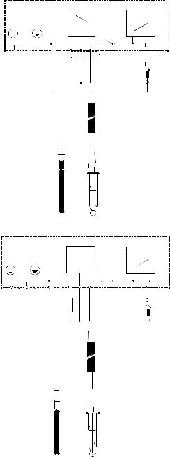
Temp. pH
PE |
N |
L |
S |
0 / PA |
|
|
|
|
|
|
|
|
|
|
|
|
|
3 |
2 |
1 |
22 |
21 |
20 |
19 |
18 |
S |
BNC
Symmetrical high-impedance connections
Measuring Cable
Potential |
pH Combination |
|
Matching Pin (PM) |
||
Electrode |
||
|
Temp. pH
PE |
N |
L |
S |
0 / PA |
|
|
|
|
|
|
|
|
|
|
|
3 |
2 |
1 |
22 |
21 |
20 |
19 |
18 |
BNC
Asymmetrical connections
Measuring Cable
|
|
|
|
|
Potential |
|
pH Combination |
||
|
||||
Matching Pin (PM) |
|
Electrode |
||
5
3.2Back Panel
The back panel consists of two connectors. The first connector is the 17-way PCB edge connector and the other is the 5-way connector.
Connection for the 17-way screw terminals (from left to right):
1.AC mains live wire |
10.No connection |
|
2.AC mains neutral wire |
11.No connection |
|
3.AC mains protective earth wire |
12.No connection |
|
4.Low set relay resting position (NC) |
13.Hold function switch terminal 1 |
|
5.Low set relay common |
14.Hold function switch terminal 2 |
|
6.Low set relay working position (NO) |
15.No connection |
|
7.High set relay resting position (NC) |
16.4 |
- 20 mA for -ve connection |
8.High set relay common |
17.4 |
- 20 mA for +ve connection |
9.High set relay working position (NO) |
|
|
Connections for the 5-way screw terminals:
18.Pt100/Pt1000 lead 1 terminal
19.Pt100/Pt1000 sense lead terminal
20.Pt100/Pt1000 lead 2 terminal
Note: If using a two-wire RTD, short terminal 19 to terminal 18.
Pt 100/Pt 1000 is selectable via an internal jumper. Factory default is Pt100. See Appendix 1 for directions on switching the RTD type.
21. pH/ORP (potential matching pin)
21. pH/ORP (shield)
6
Pt100/ |
0V/ |
S/ |
Pt1000 |
PAL |
FUSE 250VAC 100mA (F)
RELAY A |
RELAY B |
NC NC NC |
HOLD |
- |
+ |
NC |
|
||||
|
|
|
|
L N PE
7
 Loading...