


Essick Air SAS100, SAS15012, SAD10012, AD20012, SAD100 User Manual
...The New Industrial
Models
(Double Inlet)
AD100, AS100, AD10012, AS10012 AD150, AS150, AD15012, AS15012 AD20012, AS20012, AU20012
(Single Inlet)
SAD100, SAS100, SAD10012, SAS10012 SAD150, SAS150, SAD15012, SAS15012
Circle the model of your cooler and record the serial number below.
Encierre con un circulo el modelo de su enfriador y escribe el número de serie abajo.
Serial #
Número De Serie
Read And Save These Instructions
Read Carefully All Of This Manual Before
Installing The Unit.
Lea Con Cuidado Todo Este Manual Antes De Instalar La Unidad.
Vea el Español en el interior.
Table Of Contents
Safety Instructions ............................................................................. |
2 |
Operation............................................................................................ |
2 |
Installation Instructions................................................................... |
2-3 |
Maintenance Section.......................................................................... |
3 |
Troubleshooting ................................................................................. |
4 |
Warranty............................................................................................. |
4 |
Electrical Wiring Diagrams................................................................ |
5 |
General Specifications ....................................................................... |
6 |
Parts List - Wet Section (All models) ............................................. |
6-7 |
Parts List - Blower Section (AD100B, AD150B, AD200B).............. |
8 |
Parts List - Blower Section (AS100B, AS150B, AS200B)................ |
9 |
Parts List - Blower Section (AU200B) ............................................ |
10 |
Parts List - Blower Section (Single Inlet Coolers)........................... |
11 |
Motor Specifications ........................................................................ |
12 |
Pulley and Belt Kit Specifications ................................................... |
12 |
Spanish (Instrucciones en Español)............................................ |
13-16 |
110526 |
2-09 |
Safety Rules
1.Read instructions carefully.
2.Disconnect all electrical service that will be used for the unit before you begin the installation.
3.Electrical hook up should be done by a qualified electrician, so that all electrical wiring will conform to your local standards.
4.For maximum safety, make sure cooler cabinet is properly grounded to a suitable ground connection.
5.Cooler must be connected to proper line current, voltage and cycle, as stamped on cooler motor and pump motor specification plate.
6.Do not allow pump to tip over and become submerged.
7.Always TURN OFF POWER before performing any maintenance.
Operation
For the best cooling performance, if the pads are dry, pre-wet the pads by running the pump for a few minutes before starting the blower.
These coolers may also be used without water for ventilation purposes. When outside air is cool (for example, at night) or when humidity is high the water pump can be turned off.
Important: To cool efficiently, you must exhaust the stale or used air from the building. Open windows or doors or use exhaust fans located away from the cooler and in the direction you wish to cool the air. The air will flow in the direction of the exhaust openings. A common guide for the amount of exhaust opening needed is to have at least 2 square feet of opening per 1000 CFM.
Installation
 CAUTION: Make sure that the mounting surface is strong enough to support the operating weight of the cooler when in use. (For operating weight, see the general specification table.)
 CAUTION: Do not start cooler until installation is complete and unit has been tested for rigidity.
 CAUTION: Make sure all bolts are securely tightened before starting the cooler.
•Wet sections. The wet sections are bolted to the blower section using the connector brackets, lift brackets and bolts provided. Match the colored dots on the wet section to the appropriate dot on the blower section to insure correct installation.
•Ductwork. See the General Specification table for dimensions of duct opening. For down discharge units, the duct must go inside the opening. Size these ducts slightly smaller than the duct opening in the cooler. The side and up discharge units have a 1 inch flange. Size these ducts larger than the duct opening to fit over the flange of these units.
Note: Curbs are not provided. The installer is responsible for providing curbs or other means to support the cooler.
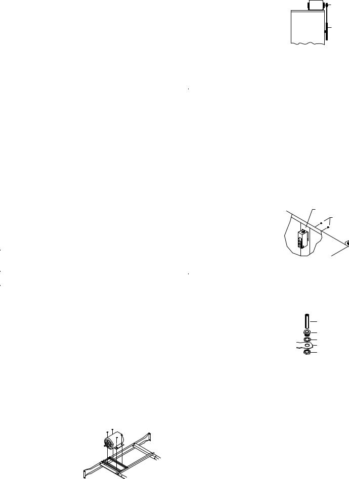
Motor Installation
• Motor mounting. Slide the |
|
|
heads of the provided carriage |
|
|
bolts into the slots of the ad- |
|
|
justable channels. Slide these |
|
|
channels sideways in the slotted |
|
|
holes to align with the holes in |
|
|
the motor base and to align the |
Fig. 1 |
|
motor shaft with the blower |
||
|
||
pulley. Mount the motor to the |
|
motor mount using these carriage bolts |
|
Motor |
and the washers and nuts provided |
|
Pulley |
(see Fig. 1). Make sure all bolts are |
|
|
securely tightened. |
Blower |
Blower |
|
Housing |
Pulley |
|
|
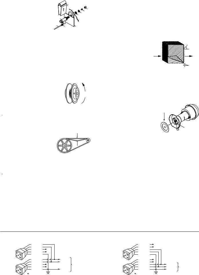
• Motor pulley. Install the motor pulley
so that it aligns with the blower pulley
(see Fig. 2) and tighten set screw. See Fig. 2 page 3 for instructions on adjusting pulley.
Electrical Connection
NOTE: Local building code regulations must be observed.
 WARNING: Disconnect all electrical services that are used for this unit before beginning any service to the cooler.
•Electrical supply. Cooler must be supplied with the proper line current, voltage and frequency, as stamped on blower motor and pump motor specification plate. See the wiring diagrams on page 4 for typical electrical connections. Note: Connecting improper voltage to motor will void motor warranty.
•Wire sizing. The conductor sizes are to be determined by motor loads and length of run per national and local electrical codes.
•Switches or contactors. Motors require switches or contactors of proper current capacity and should be sized and installed by a qualified electrician.
•Wiring. The electrical junction box
is located in the upper inside of the |
Junction Box |
divider channel. Remove the two |
Screws |
screws and pull the box out from the |
|
channel to access wiring (Fig. 3). |
|
Connect the pump supply wiring to |
|
the pump receptacles (See the pump |
|
wiring diagrams on the next page). |
Fig. 3 |
Connect the motor supply wiring |
|
directly to the blower motor. |
|
 WARNING: Make sure that cooler cabinet is properly grounded to a suitable ground connection for maximum safety.
Water Connections
•Overflow assembly. Remove nut and place nipple through the hole in the pan, with the rubber washer between the pan and the head of
the drain nipple (Fig. 4). Screw on nut and draw up tight against bottom of pan. Insert overflow pipe in nipple to retain water. Overflow pipe may be removed to drain pan when necessary. A garden hose may be screwed on the drain nipple to drain water away from your unit.
•Pump. The pump must be secured to prevent it form tipping over. Secure the pump to the pump mounting bracket (item 16 in parts drawing). Remove a nut located under the head of the pump, place the pump bolt though the hole in the mounting bracket, and secure with the nut that was previously removed. Plug pump into receptacles. Retain pump cords to internal braces to prevent cords from dropping into water reservoirs or contacting moving components.
•Supply water. Run a water supply line to the unit. Each wet section requires a 3/8 inch tube connection to the float valve. The double inlet units will have two float valves, one for each wet section. Note:
Do not use water supplied from a water softener.
•Float valve. Refer to Fig. 5 to install float. Remove items 1, 2, 3, and 4. Insert float body (5) through hole in splash plate (9) and back post panel as shown. Install washer (1) and nut (2). Tighten to
2 |
110526 |
keep float from turning. Place nut |
|
|
8 |
|
|
(4) and ferrule (3) on water supply |
|
|
|
|
|
line. Connect to float fitting and |
|
|
|
|
3 4 |
tighten until water tight. Turn on |
|
|
1 |
2 |
|
water supply and check for leaks. |
|
5 |
|
|
|
|
|
|
|
||
Loosen screw (6) and adjust rod |
7 |
|
|
|
|
(7) until water level is within 1” of |
6 |
9 |
|
|
|
top of reservoir. Tighten screw (6). |
|
Fig. 5 |
|
|
|
Slide float shield (8) over float body |
|
|
|
|
|
|
|
|
|
|
(5) until it snaps into place.
•Bleed-Off. Use of the bleed-off kit is recommended to prevent scale build up by bleeding off small amounts of circulating water during operation. Do not add any type of water treatment chemicals to the water since they may damage the evaporative media.
Pulley And Belt Adjustments
•Pulley adjustment. With an ammeter, check the motor amperage. Adjust the pulley until the amperage draw on the motor is just below that specified on the motor nameplate. To
adjust the pulley, loosen the adjustment set screw and rotate the sheave. Tighten
the set screw so that it is over a flat area, otherwise thread damage will occur. To increase amperage draw, increase pulley diameter. To decrease amperage draw, decrease pulley diameter (see Fig. 6). Recheck belt alignment.
 CAUTION: Always check the amperage of the motor after adjusting pulley to be certain it does not exceed the amperage stamped on the motor specification plate. Improper pulley adjustment will overload and burn out the motor.
• Belt tension. Loosen the motor mount |
3 Lb. |
3/4 Inches |
|
bolts and slide the motor back until the |
|
belt is properly tensioned. A 3 lb. force |
|
should deflect the belt 3/4 inches (see |
|
Fig. 7). Retighten motor mount bolts. |
Fig. 7 |
Do not adjust pulley to tighten belt.
Maintenance
 WARNING: Before doing any maintenance be sure to disconnect from power source. This is for your safety.
Spring Start-Up
•Belt tension. Check belt tension and readjust if needed.
•Grease bearings. The blower bearings in this unit should be greased once a year with a good grade of ball bearing grease.
•Cleaning pads. A clean pad is more absorbent, efficient and will give more cool air. Annually, or when required, using a garden hose with nozzle, back wash to clean out the openings, then clean off the inlet face any scale or other obstruction to the passages. Slight scraping may be required to remove hardened scale.
•Pad replacement. The pads should be replaced after 5 years or if necessary. To change pads, remove top access panel, remove grill, and disconnect water delivery tube. Remove water distributor holder and lift out media sections. Replace with the same type media. You can purchase them from your dealer.
IMPORTANT: In order to get the best performance from your cooling pads, they must be installed properly. If you have purchased a pad with two equal angles, the following instructions can be disregarded. Pads must always be installed with the steeper flute angle sloping down towards the air enter-
ing side (Fig. 8). The rea- |
|
|
son is simple. The steeper |
|
45° |
angle puts more water on |
Entering |
Leaving Air |
the hot, dry, dirty side of |
Air |
|
the pad where it is needed |
|
|
most. It also counteracts |
|
15° |
the tendency of the air to |
|
Fig. 8 |
push the water toward the |
|
|
|
|
|
back of the pad. |
|
|
•Cleaning pump. Cleaning the pump is necessary once a year at startup. For your safety, disconnect from power source and unplug pump. Remove the pump from the mount bracket. Remove the base of the pump (Fig. 9). Clean the pump and turn the impeller to ensure free operation. Remove the pump spout and check for any blockage. After cleaning, reinstall the base onto
the pump. Reattach the pump to the mount in the cooler to ensure that the pump will not overturn. Do not forget to replace the spout and water delivery tube onto the
pump outlet. The pump has au- Impeller tomatic reset thermal protection.
Pump will operate normal again after obstruction is cleared.
• Bleed off. Check bleed-off valve to be sure it is not clogged.
Winter Shut Down
•Drain water. Always drain all of the water out of the cooler and water supply line when not in use for prolonged periods, and particularly at the end of the season. Keep the water line disconnected from both the unit and water supply so that it does not freeze.
•Disconnect from power supply when not in use for extended periods of time.
•Cover unit. To protect the life of the finish, a cover for the unit is suggested in extended periods of non use.
By following the operating, installation, and maintenance suggestions as outlined, you can get many years of efficient and satisfactory service from your cooler. In the event additional information is desired, your dealer will be more than glad to assist you in every possible way.
120 Volts |
|
Pump Wiring Diagrams |
240 Volts |
|
|
|
|
|
|
||
Blue/Black |
|
|
Blue/Black |
|
|
White |
|
|
White |
|
|
Brown |
|
|
Brown |
|
|
Orange |
|
|
Orange |
|
|
Green |
|
|
Green |
|
|
Blue/Black |
Pump |
|
Blue/Black |
|
|
White |
Com. |
To |
White |
|
|
Brown |
|
Brown |
Pump |
To |
|
|
Switch |
||||
Orange |
|
Orange |
Com. |
||
|
|
Switch |
|||
Green |
Ground |
|
Green |
Ground |
|
|
|
||||
= Wire Nut |
|
|
= Wire Nut |
|
|
110526 |
3 |

Troubleshooting Guide
Problem |
|
Possible Cause |
|
Remedy |
|
|
Problem |
|
Possible Cause |
|
Remedy |
|
|
|
|
|
|
||||||||
Failure to |
1. |
No electrical power |
1. |
Check power |
|
|
Motor |
1. |
Low voltage |
1. |
Check voltage |
|
start or no air |
|
to unit |
|
|
|
|
|
cycles on |
2. |
Excessive belt tension |
2. Adjust belt tension |
|
delivery |
• Fuse blown |
• Replace fuse |
|
|
and off |
3. |
Blower shaft tight or |
3. |
Grease or replace |
|||
|
• |
Circuit breaker tripped |
• Reset breaker |
|
|
|
|
locked |
|
bearings (Disconnect |
||
|
2. |
Belt too loose or tight |
2. Adjust belt tension |
|
|
|
|
|
|
unit) |
||
|
3. |
Motor overheated |
3. |
Determine cause of |
|
|
|
4. |
Bearings dry |
4. |
Grease bearings |
|
|
|
|
|
overheating |
|
|
|
5. |
Motor pulley diameter |
5. Adjust pulley so full |
||
|
• |
Belt too tight |
• Adjust belt tension |
|
|
|
|
too large causing motor |
|
load ampere rating of |
||
|
• Blower bearings dry |
• Grease blower bear- |
|
|
|
|
overload |
|
motor is not exceeded |
|||
|
• Motor bearings dry |
|
ings |
|
|
|
6. |
Faulty motor |
6. |
Replace motor |
||
|
• Oil motor bearings |
|
|
|
|
|
|
|
||||
|
|
|
|
|
|
|||||||
|
• Motor pulley diameter |
• Adjust pulley to cor- |
|
|
Noisy |
1. |
Bearings dry |
1. |
Grease bearings |
|||
|
|
too large |
|
rect diameter |
|
|
|
2. Wheel rubbing blower |
2. |
Inspect and realign |
||
|
4. |
Motor locked |
4. |
Replace motor |
|
|
|
|
housing |
|
(Disconnect unit) |
|
|
|
|
|
|
|
|
|
|
3. |
Loose parts |
3. Tighten loose parts |
|
Inadequate |
1. |
Insufficient air exhaust |
1. |
Open windows or |
|
|
|
|||||
|
|
|
|
|
|
|
||||||
|
|
|
|
|
||||||||
air delivery |
|
|
|
doors to increase air |
|
|
Inadequate |
1. |
Inadequate exhaust in |
1. |
Open windows or |
|
with cooler |
|
|
|
flow |
|
|
cooling |
|
house |
|
doors to increase air |
|
running |
2. |
Belt too loose |
2. Adjust belt tension or |
|
|
|
2. |
Pads not wet |
|
flow |
||
|
3. |
Pads plugged |
|
replace if needed |
|
|
|
2. |
Check water distribu- |
|||
|
3. |
Clean pads |
|
|
|
• Pads plugged |
|
tion system |
||||
|
4. |
Insufficient water flow |
4. |
Clean distribution |
|
|
|
• Clean pads |
||||
|
|
over pads |
|
system |
|
|
|
• Dist. tube holes |
• Clean |
|||
|
|
|
|
|
|
|
|
|
|
clogged |
|
|
Musty or |
|
|
|
|
|
|
|
|
|
|
|
|
1. |
Stale or stagnate water |
1. |
Drain pan and clean |
|
|
|
• Pump not working |
• Replace or clean |
||||
unpleasant |
|
in cooler |
|
pads |
|
|
|
|
properly |
|
pump (Unplug) |
|
odor |
2. |
Pads not wetting |
2. |
Check water distribu- |
|
|
|
|
|
|
|
|
|
1. |
Inadequate exhaust |
|
|
||||||||
|
|
properly |
|
tion system |
|
|
Excessive |
1. |
Open doors or win- |
|||
|
• Dist. tube holes |
• Clean |
|
|
humidity in |
|
|
|
dows |
|||
|
|
clogged |
|
|
|
|
|
house |
|
|
|
|
|
• Pump not working |
• Replace or clean |
|
|
|
|
|
|
|
|||
|
|
properly |
|
pump (Unplug) |
|
|
|
|
|
|
|
|
|
• Insufficient water flow |
• Clean water distribu- |
|
|
|
|
|
|
|
|||
|
|
over pads |
|
tion system |
|
|
|
|
|
|
|
|
|
|
|
|
|
|
|
|
|
|
|
|
|
Register your product online at www.championcooler.com/eac/onlineregistration-eac.htm
Limited Warranty
This warranty is extended to the original purchaser of an evaporative cooler installed and used under normal conditions. It does not cover damages incurred through accident, neglect, or abuse by the owner. We do not authorize any person or representative to assume for us any other or different liability in connection with this product.
Terms And Conditions Of The Warranty
Lifetime Limited Coverage on water reservoir against any leakage due to defects in material. From date of purchase, if any original component part fails due to defect in material or factory workmanship only, we will provide the replacement part as follows:
One year on the cabinet components.
Two years on the evaporative media.
Exclusions From The Warranty
We are not responsible for any incidental or consequential damage resulting from any malfunction.
We are not responsible for any damage received from the use of water softeners, chemicals, de-scale material, plastic wrap, or if a motor of a higher horsepower than what is shown on the serial plate is used in the unit.
We are not responsible for the cost of service calls to diagnose cause of trouble, or labor charge to repair and/or replace parts.
How To Obtain Service Under This Warranty
Contact the Dealer where you purchased the evaporative cooler. If for any reason you are not satisfied with the response from the dealer, contact the Customer Service Department: 5800 Murray Street, Little Rock, Arkansas 72209. 1-800-643-8341. E-mail: info@championcooler.com, Web: www. championcooler.com.
This limited warranty applies to original purchaser only.
4 |
110526 |

Typical Electrical Wiring Diagrams
120 Volt, 1 Phase Electric Supply
Disconnect Switch At Cooler
See Notes 1 & 2
L
H
P
N
Gnd
Fuses
See Note 1
Cooler Cabinet
See Note 3
Equipment  Pump Motor
Ground
Blower Motor
Control Contacts
 See Note 4
L1 |
120 Volts |
|
N |
||
1 Phase |
||
Gnd |
||
Power Supply |
||
|
Main Disconnect
See Note 1
•115 Volt single phase blower motor.
•120 Volt pump motor.
•Diagram shown for two speed motor. Low speed circuit drawn with dashed lines is not required for single speed.
240 Volt, 1 Phase Electric Supply
Disconnect Switch At Cooler |
Control Contacts |
|
|||
See Notes 1 & 2 |
|
|
|||
|
L |
|
See Note 1 |
|
|
|
|
|
|
|
|
|
H |
|
|
|
|
|
P |
|
|
L1 |
|
|
120V |
|
|
208 or 240V |
|
|
L2 |
|
|
L2 |
|
|
|
|
1 Phase |
||
|
Gnd |
|
|
Gnd |
|
|
|
|
Power Supply |
||
|
|
|
Fuses |
|
|
|
Transformer |
|
Main Disconnect |
||
|
|
|
See Note 1 |
||
|
|
|
See Note 1 |
||
|
Cooler Cabinet |
|
|
||
|
|
|
|
|
|
|
See Note 3 |
• |
230 Volt single phase blower motor. |
||
|
|
||||
|
|
• |
120V pump motor shown. Trans- |
||
|
|
|
former may be omitted when a 240V |
||
|
|
|
pump is used with a 240V supply |
||
Equipment |
Pump Motor |
• |
Diagram shown for two speed motor. |
||
|
Low speed circuit drawn with dashed |
||||
|
|
||||
Ground |
|
|
lines is not required for single speed. |
||
Blower Motor |
|
|
|||
|
|
|
|
|
|
208, 240, or 480 Volt, 3 Phase Blower & 120 Volt 1 Phase Pump & Control Electric Supply
Motor Starter With
Overload Protection
Sized To Match Motor
Full Load Current
See Note 1
T3
T2
T1
Gnd
Disconnect Switch
At Cooler
See Notes 1 & 2
Equipment
Ground
|
|
Gnd |
208, 240, or 480V |
|
|
|
L1 |
||
|
|
L2 |
3 Phase |
|
Control Contacts |
|
L3 |
Power Supply |
|
|
Main Disconnects |
|||
See Note 4 H |
|
|||
P |
|
See Note 1 |
|
|
|
L1 |
120V |
||
N |
|
N |
||
|
1 Phase |
|||
Gnd |
|
Gnd |
||
|
Power Supply |
|||
Fuses |
|
|
||
|
|
|
||
See Note 1 |
|
|
|
|
Disconnect Switch At Cooler |
|
|||
See Note 1&2 |
• |
Three phase single speed blower motor |
||
Cooler Cabinet |
||||
• |
Three pole motor starter with overload |
|||
|
||||
See Note 3 |
|
protection |
|
|
Pump Motor |
• |
120V single phase control and pump shown. |
||
|
If 240V control and pump are to be used, then |
|||
|
|
|||
Blower Motor |
|
both legs of power supply must be fused. |
||
Typical Control Contacts
Function and Connection
L |
- |
Low Fan |
P |
- |
Pump |
H |
- |
Hi Fan |
L1 - Supply Power
Function |
Connection |
Off |
None |
Pump Only |
L1-P |
Hi-Cool |
L1-H |
* Low-Cool |
L1-L & L1-P |
Hi-Fan |
L1-H |
* Low-Fan |
L1-L |
* Omit for single speed blower motor
208, 240, or 480 Volt, 3 Phase Blower Electric Supply With Transformer For Pump & Control
Motor Starter With |
|
|
Overload Protection |
|
|
Sized To Match Motor |
|
|
Full Load Current |
|
|
See Note 1 |
Control Contacts |
|
|
See Note 4 |
|
|
H |
|
|
P |
120 |
|
|
V |
|
Disconnect Switch At Cooler |
|
T3 |
See Notes 1 & 2 |
|
T2 |
|
|
T1 |
Cooler Cabinet |
|
Gnd |
|
|
Disconnect Switch At Cooler |
See Note 3 |
|
|
|
|
See Notes 1 & 2 |
Pump Motor |
|
|
|
|
Equipment |
Blower Motor |
|
Ground |
|
|
Gnd |
208, 240 or 480V |
L1 |
|
L2 |
3 Phase |
L3 |
Power Supply |
Main Disconnect
See Note 1
Fuses
See Note 1
Transformer
See Note 1
•Three phase single speed blower motor.
•Three pole motor starter with overload protection.
•120V single phase pump powered by a transformer. Transformer may be omitted when 240V control & pump are used with a 240V supply.
 WARNING: Electrical hookup should be performed by a qualified electrician. All electrical wiring must conform to national and local standards.
NOTE 1. All switches, motor starters, transformers, fuses, junction boxes, receptacles, receptacle boxes, cover plates, and conductors shall be supplied by the installer.
NOTE 2. The national electric code requires a disconnect switch located at equipment if the main disconnect at equipment controller is not visible from the equipment. If more than one disconnect is used they must be mounted adjacent to one another.
NOTE 3. A receptacle for a NEMA 5-15P plug is required for 120V recirculating pump and a receptacle for a NEMA 6-15P plug for 230V pump. NOTE 4. The control contacts may be part of a switch, thermostat or other control device.
110526 |
5 |
 Loading...