


 Loading...
V7
Record of Revisions
Reference numbers are shown at the bottom left corner on the back cover of each manual.
Printing Date |
Reference No. |
Revised Contents |
|
|
|
September, 2002 |
2010NE0 |
First edition |
|
|
|
|
|
|

Preface
Thank you for selecting the MONITOUCH V7 series.
For correct set-up of MONITOUCH, you are requested to read through this manual to understand more about the product.
For more information about the V7 series, refer to the following related manuals.
Manual Name |
Contents |
Reference No. |
|
|
|
Reference Manual (Operation) |
The V-SFT operating procedure is described. |
1043NE |
|
|
|
Reference Manual (Function) |
The functions and instructions of the V7/V6 series are |
1044NE |
|
explained. |
|
|
|
|
Universal Serial Connection Manual |
Universal serial specifications and commands are |
1021NE |
|
described. |
|
|
|
|
Temperature Control Network |
The temperature control network function is explained. |
1033NE |
|
|
|
Specifications for Communication |
Instructions for CC-LINK are contained. |
1028NE |
Unit CC-LINK |
|
|
|
|
|
Specifications for Communication |
Instructions for PROFIBUS-DP are contained. |
1036NE |
Unit PROFIBUS-DP |
|
|
|
|
|
M-CARD SFTE Operation Manual |
The operating procedure of the memory card editor is |
1023NE |
|
described. |
|
|
|
|
For further details about PLCs (programmable logic controllers), see the manual attached to each PLC.
Notes:
1.This manual may not, in whole or in part, be printed or reproduced without the prior written consent of Hakko Electronics Co., Ltd.
2.Information in this manual is subject to change without prior notice.
3.Windows and Excel are registered trademarks of Microsoft Corporation in the United States and other countries.
4.All other company names or product names are trademarks or registered trademarks of their respective holders.
5.This manual is intended to give accurate information about MONITOUCH hardware. If you have any questions, please contact your local distributor.
Notes on Safe Use of
MONITOUCH
In this manual, you will find various notes categorized under the following levels with the signal words “DANGER,” and “CAUTION.”
DANGER |
Indicates an imminently hazardous situation which, if not avoided, will result in |
|
death or serious injury. |
||
|
||
|
|
|
|
|
|
CAUTION |
Indicates a potentially hazardous situation which, if not avoided, may result in |
|
minor or moderate injury and could cause property damage. |
||
|
||
|
|
Note that there is a possibility that the item listed with |
CAUTION may have serious |
ramifications. |
|
 DANGER
•Never use the input function of MONITOUCH for operations that may threaten human life or to damage the system, such as switches to be used in case of emergency. Please design the system so that it can cope with malfunction of a touch switch.
•Turn off the power supply when you set up the unit, connect cables or perform maintenance and inspection. Failure to do so could cause an electric shock or damage to the unit.
•Never touch any terminals while the power is on. An electric shock may occur.
•You must put a cover on the terminals on the unit when you turn the power on and operate the unit. Without the terminal cover in place, an electric shock may occur.
•The liquid crystal in the LCD panel is a hazardous substance. If the LCD panel is damaged, never swallow the leaked liquid crystal. If the liquid crystal spills on your skin or clothing, use soap and wash off thoroughly.

 CAUTION
[Notes on System Design]
•Never bundle control cables and input/output cables with high-voltage and large-current carrying cables such as power supply cables. Keep these cables at least 200 mm away from the power supply or high-voltage cables. Otherwise, malfunction may occur due to noise.
•For use in a nuclear energy facility, or other facility of such official importance, please consult your local distributor.
[Notes on Installation]
•Operate (or store) MONITOUCH under the conditions indicated in this manual and related manuals. Failure to do so could cause fire, malfunction, physical damage or deterioration.
•Understand the following environmental limits for use and storage of MONITOUCH. Otherwise, fire or damage to the unit may result.
-Avoid locations where there is a possibility that water, corrosive gas, flammable gas, solvents, grinding fluids or cutting oil can come into contact with the unit.
-Avoid high temperature, high humidity, and outside weather conditions, such as wind, rain or direct sunlight.
-Avoid locations where excessive dust, salt, and metallic particles are present.
-Avoid installing the unit in a location where vibration or physical shock may be transmitted.
•Equipment must be correctly mounted so that the main terminal of MONITOUCH will not be touched inadvertently.
•Tighten the MONITOUCH mounting screws to the specified torque. Excessive tightening may distort the panel surface. Loose tightening may cause MONITOUCH to come off, malfunction or be short-circuited.
•Tighten terminal screws on the power input terminal block equally to a torque of 0.5 N•m.
•Check the appearance of MONITOUCH when it is unpacked. Do not use the unit if any damage or deformation is found.
•MONITOUCH has a glass screen. Do not drop or give physical shock to the unit.
[Notes on Cable Connection]
•Connect the cables correctly to the terminals of MONITOUCH in accordance with the specified voltage and wattage. Over-voltage, over-wattage or incorrect cable connection could cause fire, malfunction or damage to the unit.
•Be sure to establish a ground of MONITOUCH. The FG terminal must be used exclusively for the unit with the level of grounding resistance less than 100 Ω.
•Prevent any conductive particles from entering into MONITOUCH. Failure to do so may lead to fire, damage or malfunction.
(To be continued)
 CAUTION
[Notes on Maintenance and Operation]
•Hakko Electronics Co., Ltd. is not responsible for any damages resulting from repair, overhaul or modification of MONITOUCH that was performed by an unauthorized person.
•Do not use thinners for cleaning because they may discolor the MONITOUCH surface. Use alcohol or benzine commercially available.
•Do not use a sharp-pointed tool when pressing a touch switch.
•Only experts are authorized to set up the unit, connect the cables or perform maintenance and inspection.
•MONITOUCH is equipped with a lithium battery. Lithium batteries contain combustible material such as lithium or organic solvent. Mishandling may cause heat, explosion or ignition resulting in fire or injury. Read this manual and related manuals carefully and handle the lithium battery correctly as instructed.
•If a data receive error occurs when MONITOUCH and the counterpart (PLC, temperature controller, etc.) are started at the same time, read the manual for the counterpart unit and handle the error correctly.
•Switch resolution of the MONITOUCH V7 series is determined by the analog-type resistance film. Do not press two or more
positions on the screen at the same time.
SYSTEM
F1
F2
F3
If two or more positions are pressed at the same time, the switch located between the pressed positions activates. Please take note of this.
|
F4 |
|
F5 |
SWITCH |
F6 |
|
F7 |
 POWER
POWER
[Notes on Disposal]
Pressing two positions at the same time activates the switch in the center.
• At the time of disposal, MONITOUCH must be treated as industrial waste.

Contents
Chapter 1 |
Hardware Specifications |
|
|
1. |
Features .......................................................................................................................... |
1-1 |
|
2. |
Models and Peripheral Equipment .................................................................................. |
1-2 |
|
|
|
MONITOUCH Models .................................................................................................................. |
1-2 |
|
|
Peripheral Equipment .................................................................................................................. |
1-3 |
3. |
System Composition ....................................................................................................... |
1-7 |
|
|
|
System Composition of V7 (Standard)......................................................................................... |
1-7 |
|
|
System Composition of V7i (High-performance).......................................................................... |
1-8 |
4. |
Specifications .................................................................................................................. |
1-9 |
|
|
|
General Specifications ................................................................................................................. |
1-9 |
|
|
Display Specifications ................................................................................................................ |
1-10 |
|
|
Touch Panel Specifications........................................................................................................ |
1-10 |
|
|
Function Switch Specifications .................................................................................................. |
1-11 |
|
|
Interface Specifications.............................................................................................................. |
1-11 |
|
|
Clock and Backup Memory Specifications................................................................................. |
1-11 |
|
|
Drawing Environment................................................................................................................. |
1-12 |
|
|
Display Function Specifications ................................................................................................. |
1-12 |
|
|
Function Performance Specifications ........................................................................................ |
1-13 |
5. |
Dimensions and Panel Cut-out...................................................................................... |
1-14 |
|
|
|
V708/V708i External View and Dimensions............................................................................... |
1-14 |
|
|
V710/V710i External View and Dimensions............................................................................... |
1-15 |
|
|
V712/V712i External View and Dimensions............................................................................... |
1-16 |
6. |
Names and Functions of Components .......................................................................... |
1-17 |
|
7. |
Mounting Procedure ...................................................................................................... |
1-20 |
|
|
|
Mounting Procedure................................................................................................................... |
1-20 |
|
|
Mounting Angle .......................................................................................................................... |
1-20 |
8. |
Power Supply Cable Connection................................................................................... |
1-21 |
|
|
|
Power Supply Cable Connection ............................................................................................... |
1-21 |
|
|
Notes on Usage of 100-240 VAC Specifications ....................................................................... |
1-22 |
|
|
Grounding .................................................................................................................................. |
1-22 |
9. |
Coin-type Lithium Battery .............................................................................................. |
1-23 |
|
|
|
Battery Mounting Procedure ...................................................................................................... |
1-23 |
|
|
Battery Replacement ................................................................................................................. |
1-24 |
10. DIP Switch Setting......................................................................................................... |
1-26 |
||
|
|
DIP Switch (DIPSW) Setting ...................................................................................................... |
1-26 |
11. Serial Connector (CN1) ................................................................................................. |
1-28 |
||
Serial Connector for PLC Connection........................................................................................ |
1-28 |

12. Modular Jack (MJ1/MJ2)................................................................................................ |
1-29 |
Modular Jack 1 (MJ1)/2 (MJ2) ................................................................................................... |
1-29 |
V-SFT Setting ............................................................................................................................ |
1-30 |
Transferring Screen Data........................................................................................................... |
1-32 |
Barcode Reader Connection...................................................................................................... |
1-32 |
13. |
10BASE-T (LAN)............................................................................................................ |
1-33 |
|
10BASE-T Connector ................................................................................................................ |
1-33 |
|
Notes on Wiring ......................................................................................................................... |
1-34 |
14. |
CF Card (CF) ................................................................................................................. |
1-35 |
|
Recommended CF Card ............................................................................................................ |
1-35 |
|
Mounting and Dismounting the CF Card.................................................................................... |
1-35 |
|
Notes on Handling the CF Card................................................................................................. |
1-36 |
15. |
Printer Connection (PRINTER) ...................................................................................... |
1-37 |
|
Printer Connector (PRINTER).................................................................................................... |
1-37 |
|
Connection with Printer through Serial Interface ....................................................................... |
1-38 |
Chapter 2 |
MONITOUCH Operations |
|
1. Operation of V7 Main Menu ............................................................................................. |
2-1 |
|
Initial Screen ................................................................................................................................ |
2-1 |
|
1. |
Main Menu Screen .............................................................................................................. |
2-2 |
2. |
I/O Test ............................................................................................................................... |
2-4 |
2-1. |
Self-loop Test ...................................................................................................................... |
2-5 |
2-2. |
Print Check.......................................................................................................................... |
2-8 |
2-3. SYSTEM & Function Switch Test........................................................................................ |
2-8 |
|
2-4. |
Touch Switch Test............................................................................................................... |
2-9 |
3. |
Card Menu Screen ............................................................................................................ |
2-11 |
3-1. |
CREC Menu Screen.......................................................................................................... |
2-12 |
3-2. Transferring Screen Data from a CF Card ........................................................................ |
2-15 |
|
3-3. Saving Backup Copies of SRAM....................................................................................... |
2-21 |
|
3-4. Messages during Data Transfer........................................................................................ |
2-23 |
|
4. |
Ethernet............................................................................................................................. |
2-24 |
5. |
SRAM/Clock...................................................................................................................... |
2-27 |
6. |
Extension Program Information......................................................................................... |
2-28 |
7. |
Extended Function Setting ................................................................................................ |
2-29 |
2. Function Switches.......................................................................................................... |
2-30 |
|
Types ......................................................................................................................................... |
2-30 |
|
[SYSTEM] Switch....................................................................................................................... |
2-30 |
|
3. Errors Displayed on the V7 Series................................................................................. |
2-32 |
|
1. |
Communication Error ........................................................................................................ |
2-32 |
2. |
Check ................................................................................................................................ |
2-36 |
3. |
Warning............................................................................................................................. |
2-36 |
4. |
SYSTEM ERROR ............................................................................................................. |
2-37 |
5. |
Touch Switch is Active ...................................................................................................... |
2-37 |

Chapter 3 |
Serial Communications |
|
|
1. |
1 : 1 Connection .............................................................................................................. |
3-1 |
|
|
|
1 : 1 Connection........................................................................................................................... |
3-1 |
|
|
Wiring........................................................................................................................................... |
3-2 |
|
|
V-SFT Setting .............................................................................................................................. |
3-4 |
2. |
1 : n Connection (Multi-drop)........................................................................................... |
3-9 |
|
|
|
1 : n Connection........................................................................................................................... |
3-9 |
|
|
Wiring (RS-422/485) .................................................................................................................... |
3-9 |
|
|
V-SFT Setting ............................................................................................................................ |
3-10 |
|
|
Notes on Communication Errors................................................................................................ |
3-10 |
3. n : 1 Connection (Multi-link 2)........................................................................................ |
3-11 |
||
|
|
Multi-link 2.................................................................................................................................. |
3-11 |
|
|
Wiring......................................................................................................................................... |
3-12 |
|
|
V-SFT Setting ............................................................................................................................ |
3-14 |
|
|
Communication Error ................................................................................................................. |
3-15 |
4. |
n : 1 Connection (Multi-link)........................................................................................... |
3-16 |
|
|
|
Multi-link..................................................................................................................................... |
3-16 |
|
|
Wiring......................................................................................................................................... |
3-17 |
|
|
V-SFT Setting ............................................................................................................................ |
3-18 |
5. |
Universal Serial Communications ................................................................................. |
3-20 |
|
|
|
Universal Serial Communications .............................................................................................. |
3-20 |
6. |
V-Link ............................................................................................................................ |
3-21 |
|
|
|
V-Link......................................................................................................................................... |
3-21 |
|
|
Wiring......................................................................................................................................... |
3-22 |
|
|
V-SFT Setting ............................................................................................................................ |
3-24 |
|
|
Protocol...................................................................................................................................... |
3-25 |
|
|
NAK: Error Codes ...................................................................................................................... |
3-29 |
|
|
1-byte Character Code List ........................................................................................................ |
3-30 |
7. |
PLC2Way ...................................................................................................................... |
3-31 |
|
|
|
PLC2Way................................................................................................................................... |
3-31 |
|
|
Limitations on Connection at the MJ Port .................................................................................. |
3-32 |
|
|
PLCs Compatible with PLC2Way Connection at MJ Port.......................................................... |
3-32 |
|
|
Wiring......................................................................................................................................... |
3-33 |
|
|
V-SFT Setting – System Setting ................................................................................................ |
3-35 |
|
|
V-SFT Setting – When the temperature control network/PLC2Way table is used:.................... |
3-38 |
|
|
Indirect Memory Designation ..................................................................................................... |
3-45 |
|
|
User Log Read for YOKOGAWA’s PLC..................................................................................... |
3-46 |
|
|
Processing Cycle ....................................................................................................................... |
3-47 |
|
|
Notes on Screen Data Transfer ................................................................................................. |
3-48 |
|
|
System Memory ......................................................................................................................... |
3-49 |
8. |
Temperature Control Network ....................................................................................... |
3-52 |
|
Temperature Control Network.................................................................................................... |
3-52 |
Chapter 4 |
Network Communications |
|
|
1. |
Ethernet ........................................................................................................................... |
4-1 |
|
|
|
Ethernet ....................................................................................................................................... |
4-1 |
|
|
Notes on Ethernet Communications ............................................................................................ |
4-3 |
|
|
IP Address for the V7 Series........................................................................................................ |
4-3 |
|
|
Communication Interface Unit CU-03 .......................................................................................... |
4-3 |
|
|
Wiring........................................................................................................................................... |
4-5 |
|
|
Transferring Screen Data............................................................................................................. |
4-8 |
|
|
V-SFT Setting (PLC Type/Communication Parameter) ............................................................. |
4-10 |
|
|
V-SFT Setting (Network Table Editing)...................................................................................... |
4-14 |
|
|
V-SFT Setting (Macro) ............................................................................................................... |
4-19 |
|
|
System Memory ......................................................................................................................... |
4-22 |
|
|
Ethernet Access Functions (HKEtn10.DLL)............................................................................... |
4-26 |
|
|
Server Communication Procedure............................................................................................. |
4-44 |
|
|
Error Display .............................................................................................................................. |
4-45 |
2. |
FL-net (OPCN-2)............................................................................................................ |
4-48 |
|
|
|
FL-net (OPCN-2)........................................................................................................................ |
4-48 |
3. |
MELSECNET/10 ............................................................................................................ |
4-49 |
|
|
|
MELSECNET/10 ........................................................................................................................ |
4-49 |
4. |
CC-Link .......................................................................................................................... |
4-51 |
|
|
|
CC-Link ...................................................................................................................................... |
4-51 |
5. |
OPCN-1 ......................................................................................................................... |
4-52 |
|
|
|
OPCN-1 ..................................................................................................................................... |
4-52 |
6. |
T-LINK............................................................................................................................ |
4-53 |
|
|
|
T-LINK........................................................................................................................................ |
4-53 |
7. |
PROFIBUS-DP .............................................................................................................. |
4-54 |
|
|
|
PROFIBUS................................................................................................................................. |
4-54 |

Chapter 5 |
Connection to PLCs |
|
|
1. |
MITSUBISHI PLC............................................................................................................ |
5-1 |
|
|
|
Available PLCs............................................................................................................................. |
5-1 |
|
|
Communication Setting................................................................................................................ |
5-4 |
|
|
A Series Link, QnA Series Link: Switch Setting ........................................................................... |
5-6 |
|
|
Available Memory ........................................................................................................................ |
5-8 |
|
|
Wiring......................................................................................................................................... |
5-11 |
|
|
A Link + Net10 ........................................................................................................................... |
5-15 |
|
|
V-MDD (Dual Port Interface)...................................................................................................... |
5-17 |
|
|
Ladder Transfer Function........................................................................................................... |
5-18 |
2. |
OMRON PLC................................................................................................................. |
5-22 |
|
|
|
Available PLCs........................................................................................................................... |
5-22 |
|
|
Communication Setting.............................................................................................................. |
5-24 |
|
|
Available Memory ...................................................................................................................... |
5-25 |
|
|
Wiring......................................................................................................................................... |
5-26 |
|
|
SYSMAC CS1 DNA ................................................................................................................... |
5-29 |
3. |
SHARP PLC .................................................................................................................. |
5-30 |
|
|
|
Available PLCs........................................................................................................................... |
5-30 |
|
|
Communication Setting.............................................................................................................. |
5-30 |
|
|
JW Series: Link Unit Switch Setting........................................................................................... |
5-31 |
|
|
JW100/70H COM Port, JW20 COM Port: System Memory Setting........................................... |
5-31 |
|
|
Available Memory ...................................................................................................................... |
5-32 |
|
|
Wiring......................................................................................................................................... |
5-33 |
4. |
HITACHI PLC ................................................................................................................ |
5-35 |
|
|
|
Available PLCs........................................................................................................................... |
5-35 |
|
|
Communication Setting.............................................................................................................. |
5-36 |
|
|
HIDIC-H: Switch Setting............................................................................................................. |
5-37 |
|
|
Available Memory ...................................................................................................................... |
5-37 |
|
|
Wiring......................................................................................................................................... |
5-39 |
5. |
MATSUSHITA PLC ....................................................................................................... |
5-41 |
|
|
|
Available PLCs........................................................................................................................... |
5-41 |
|
|
Communication Setting.............................................................................................................. |
5-41 |
|
|
MEWNET: Link Unit Switch Setting ........................................................................................... |
5-42 |
|
|
Available Memory ...................................................................................................................... |
5-42 |
|
|
Wiring......................................................................................................................................... |
5-43 |
6. |
YOKOGAWA PLC ......................................................................................................... |
5-45 |
|
|
|
Available PLCs........................................................................................................................... |
5-45 |
|
|
Communication Setting.............................................................................................................. |
5-46 |
|
|
Available Memory ...................................................................................................................... |
5-47 |
|
|
Wiring......................................................................................................................................... |
5-48 |
7. |
YASKAWA PLC............................................................................................................. |
5-50 |
|
|
|
Available PLCs........................................................................................................................... |
5-50 |
|
|
Communication Setting.............................................................................................................. |
5-50 |
|
|
Available Memory ...................................................................................................................... |
5-51 |
|
|
Wiring......................................................................................................................................... |
5-52 |

8. Toyopuc PLC ................................................................................................................. |
5-55 |
Available PLCs........................................................................................................................... |
5-55 |
Communication Setting.............................................................................................................. |
5-55 |
Switch Setting ............................................................................................................................ |
5-55 |
Available Memory ...................................................................................................................... |
5-56 |
Screen Editing (Memory Input) .................................................................................................. |
5-56 |
Wiring......................................................................................................................................... |
5-57 |
9. FUJI PLC ....................................................................................................................... |
5-58 |
Available PLCs........................................................................................................................... |
5-58 |
Communication Setting.............................................................................................................. |
5-58 |
MICREX-F Series, FLEX-PC Series: Switch Setting ................................................................. |
5-59 |
Available Memory ...................................................................................................................... |
5-60 |
Wiring......................................................................................................................................... |
5-62 |
10. KOYO PLC..................................................................................................................... |
5-64 |
Available PLCs........................................................................................................................... |
5-64 |
Communication Setting.............................................................................................................. |
5-65 |
Available Memory ...................................................................................................................... |
5-66 |
Switch Setting ............................................................................................................................ |
5-67 |
Wiring......................................................................................................................................... |
5-69 |
11. Allen-Bradley PLC.......................................................................................................... |
5-72 |
Available PLCs........................................................................................................................... |
5-72 |
Communication Setting.............................................................................................................. |
5-73 |
Available Memory ...................................................................................................................... |
5-74 |
PLC-5 Series: Switch Setting..................................................................................................... |
5-76 |
SLC500 Series, Micro Logix 100: Transmission Parameter Setting .......................................... |
5-78 |
Wiring......................................................................................................................................... |
5-79 |
12. GE Fanuc PLC............................................................................................................... |
5-82 |
Available PLCs........................................................................................................................... |
5-82 |
Communication Setting.............................................................................................................. |
5-82 |
Available Memory ...................................................................................................................... |
5-83 |
Wiring......................................................................................................................................... |
5-84 |
13. TOSHIBA PLC ............................................................................................................... |
5-86 |
Available PLCs........................................................................................................................... |
5-86 |
Communication Setting.............................................................................................................. |
5-86 |
Available Memory ...................................................................................................................... |
5-87 |
Wiring......................................................................................................................................... |
5-87 |
14. TOSHIBA MACHINE PLC.............................................................................................. |
5-88 |
Available PLCs........................................................................................................................... |
5-88 |
Communication Setting.............................................................................................................. |
5-88 |
Available Memory ...................................................................................................................... |
5-88 |
Wiring......................................................................................................................................... |
5-89 |
15. SIEMENS PLC............................................................................................................... |
5-90 |
Available PLCs........................................................................................................................... |
5-90 |
Communication Setting.............................................................................................................. |
5-90 |
Available Memory ...................................................................................................................... |
5-92 |
Wiring......................................................................................................................................... |
5-95 |

16. SHINKO PLC................................................................................................................. |
5-98 |
Available PLCs........................................................................................................................... |
5-98 |
Communication Setting.............................................................................................................. |
5-98 |
Available Memory ...................................................................................................................... |
5-98 |
Wiring......................................................................................................................................... |
5-99 |
17. SAMSUNG PLC .......................................................................................................... |
5-100 |
Available PLCs......................................................................................................................... |
5-100 |
Communication Setting............................................................................................................ |
5-100 |
Available Memory .................................................................................................................... |
5-100 |
Wiring....................................................................................................................................... |
5-101 |
18. KEYENCE PLC ........................................................................................................... |
5-102 |
Available PLCs......................................................................................................................... |
5-102 |
Communication Setting............................................................................................................ |
5-103 |
Available Memory .................................................................................................................... |
5-104 |
Wiring....................................................................................................................................... |
5-106 |
19. LG PLC........................................................................................................................ |
5-108 |
Available PLCs......................................................................................................................... |
5-108 |
Communication Setting............................................................................................................ |
5-108 |
Available Memory .................................................................................................................... |
5-109 |
Wiring....................................................................................................................................... |
5-111 |
20. FANUC PLC ................................................................................................................ |
5-113 |
Available PLCs......................................................................................................................... |
5-113 |
Communication Setting............................................................................................................ |
5-113 |
Available Memory .................................................................................................................... |
5-113 |
Wiring....................................................................................................................................... |
5-114 |
21. FATEK AUTOMATION PLC........................................................................................ |
5-116 |
Available PLCs......................................................................................................................... |
5-116 |
Communication Setting............................................................................................................ |
5-116 |
Available Memory .................................................................................................................... |
5-116 |
Wiring....................................................................................................................................... |
5-117 |
22. IDEC PLC.................................................................................................................... |
5-118 |
Available PLCs......................................................................................................................... |
5-118 |
Communication Setting............................................................................................................ |
5-118 |
Available Memory .................................................................................................................... |
5-118 |
Wiring....................................................................................................................................... |
5-119 |
23. MODICON PLC ........................................................................................................... |
5-120 |
Available PLCs......................................................................................................................... |
5-120 |
Communication Setting............................................................................................................ |
5-120 |
Available Memory .................................................................................................................... |
5-120 |
Wiring....................................................................................................................................... |
5-121 |
24. YAMATAKE PLC......................................................................................................... |
5-122 |
Available PLCs......................................................................................................................... |
5-122 |
Communication Setting............................................................................................................ |
5-122 |
Available Memory .................................................................................................................... |
5-122 |
Wiring....................................................................................................................................... |
5-123 |

25. TAIAN PLC .................................................................................................................. |
5-124 |
Available PLCs......................................................................................................................... |
5-124 |
Communication Setting............................................................................................................ |
5-124 |
Available Memory .................................................................................................................... |
5-124 |
Wiring....................................................................................................................................... |
5-125 |
26. SAIA PLC..................................................................................................................... |
5-126 |
Available PLCs......................................................................................................................... |
5-126 |
Communication Setting............................................................................................................ |
5-126 |
S-BUS Configuration................................................................................................................ |
5-126 |
Available Memory .................................................................................................................... |
5-126 |
Wiring....................................................................................................................................... |
5-127 |
27. MOELLER PLC............................................................................................................ |
5-128 |
Available PLCs......................................................................................................................... |
5-128 |
Communication Setting............................................................................................................ |
5-128 |
Available Memory .................................................................................................................... |
5-128 |
Wiring....................................................................................................................................... |
5-129 |
28. Telemecanique PLC .................................................................................................... |
5-130 |
Available PLCs......................................................................................................................... |
5-130 |
Communication Setting............................................................................................................ |
5-130 |
Available Memory .................................................................................................................... |
5-130 |
Wiring....................................................................................................................................... |
5-131 |
29. Automationdirect PLC .................................................................................................. |
5-132 |
Available PLCs......................................................................................................................... |
5-132 |
Communication Setting............................................................................................................ |
5-132 |
Available Memory .................................................................................................................... |
5-133 |
Wiring....................................................................................................................................... |
5-133 |

Hardware
Specifications
1.Features
2.Models and Peripheral Equipment
3.System Composition
4.Specifications
5.Dimensions and Panel Cut-out
6.Names and Functions of Components
7.Mounting Procedure
8.Power Supply Cable Connection
9.Coin-type Lithium Battery
10.DIP Switch Setting
11.Serial Connector (CN1)
12.Modular Jack (MJ1/MJ2)
13.10BASE-T (LAN)
14.CF Card (CF)
15.Printer Connection (PRINTER)

1. Features |
1-1 |
1.Features
The V7 series inherits and heightens the features of the V6 series as described below.
1.32k-color Display
32,768-color display makes colorful expression possible. Bitmap files are clearly displayed in brilliant colors.
2.CF Card Interface as Standard
The CF card can be used for saving multiple screen data, sampling data, recipe data, hard copy images, and other various usages. Large-sized video capture images, JPEG or WAV files can be saved.
3.Connector for 10BASE-T (for high-performance type only)
This connector enables Ethernet connection with a host computer. High-speed communications are possible via Ethernet for uploading/downloading screen data and reading/writing data from/to the server.
4.Video Display Upgraded (for high-performance type only, optional)
The video display function is upgraded drastically to allow: saving the current video screen, taking snapshots of multiple exposures, superimposing a semi-transparent operation screen on a video display, showing four video channels at the same time, and so on.
5.Web Server Function (for high-performance type only)
The V7i screens are converted into HTML files and displayed on the WWW browser using the Ethernet.
6.Animation Function
The animation function enables representation of the field close to the real image.
7.Play of WAV File (for high-performance type only, optional)
WAV files can be played with ease simply by connecting the option unit to the speaker. It is possible to use sound for notifying the field conditions, such as an occurrence of an error. The monitoring operator can work from a distance.
1
Specifications Hardware
1-2 2. Models and Peripheral Equipment
2.Models and Peripheral Equipment
MONITOUCH Models
The model name consists of the following information.
V 7 


 Power supply specification
D: 24 VDC specification (in compliance with CE/UL/cUL) None: 100-240 VAC specification
Device specification
S:TFT color LCD (SVGA)
T:TFT color LCD (VGA)
C:STN color LCD (VGA)
Functional specification
i: High-performance type None: Standard type
Screen size
08:8-inch
10:10-inch
12:12-inch

|
|
2. Models and Peripheral Equipment |
1-3 |
|
|
|
|
|
|
The following models are available. |
|
|
||
|
|
|
|
|
Series and |
Model |
Specifications |
Remarks |
|
Size |
Name |
|
||
|
|
|
||
|
|
|
|
|
|
V708SD |
TFT color, 800 × 600 dots, standard, DC power supply |
Compliant with CE/UL/cUL |
|
V708 series |
|
|
|
|
V708iSD |
TFT color, 800 × 600 dots, high-performance, DC power |
Compliant with CE/UL/cUL |
||
8-inch |
|
supply |
|
|
|
|
|
|
|
|
V708CD |
STN color, 640 × 480 dots, standard, DC power supply |
Compliant with CE/UL/cUL |
|
|
|
|
|
|
|
V710T |
TFT color, 640 × 480 dots, standard, AC power supply |
|
|
|
|
|
|
|
|
V710TD |
TFT color, 640 × 480 dots, standard, DC power supply |
Compliant with CE/UL/cUL |
|
|
|
|
|
|
|
V710iT |
TFT color, 640 × 480 dots, high-performance, AC power |
|
|
|
|
supply |
|
|
|
|
|
|
|
|
V710iTD |
TFT color, 640 × 480 dots, high-performance, DC power |
Compliant with CE/UL/cUL |
|
V710 series |
|
supply |
|
|
10-inch |
V710S |
TFT color, 800 × 600 dots, standard, AC power supply |
|
|
|
|
|
|
|
|
V710SD |
TFT color, 800 × 600 dots, standard, DC power supply |
Compliant with CE/UL/cUL |
|
|
|
|
|
|
|
V710iS |
TFT color, 800 × 600 dots, high-performance, AC power |
|
|
|
|
supply |
|
|
|
|
|
|
|
|
V710iSD |
TFT color, 800 × 600 dots, high-performance, DC power |
Compliant with CE/UL/cUL |
|
|
|
supply |
|
|
|
|
|
|
|
|
V712S |
TFT color, 800 × 600 dots, standard, AC power supply |
|
|
|
|
|
|
|
|
V712SD |
TFT color, 800 × 600 dots, standard, DC power supply |
Compliant with CE/UL/cUL |
|
V712 series |
|
|
|
|
V712iS |
TFT color, 800 × 600 dots, high-performance, AC power |
|
|
|
12-inch |
|
supply |
|
|
|
|
|
|
|
|
V712iSD |
TFT color, 800 × 600 dots, high-performance, DC power |
Compliant with CE/UL/cUL |
|
|
|
supply |
|
|
|
|
|
|
|
Peripheral Equipment
The following options are available for using the V7 series more effectively.
V-SFT (drawing software: English version)
Application software for editing display data for the V series. (Windows98/NT4.0/Me/2000/XP compatible) The V7 series is supported with ver. 2.00 and later.
1
Specifications Hardware
1-4 2. Models and Peripheral Equipment
EU-xx (option unit)
(* This option unit can only be mounted on the V7i model.) xx: 00 → Video input + sound output unit
Video images can be displayed on V7i directly. WAV files can be played at an external speaker.
xx: 01 → RGB input + sound output unit
Screen images displayed on a CRT display can be shown on V7i. WAV files can be played at an external speaker.
xx: 02 → RGB output + sound output unit
Screen images displayed on V7i can be shown on a CRT display. WAV files can be played at an external speaker.
xx: 03 → Sound output unit
WAV files can be played at an external speaker.
V7EM-F (FLASH memory cassette)
Extension print circuit board to extend the memory for screen data. The capacity of FLASH memory is 8 Mbyte.
V7EM-S (SRAM cassette)
Extension print circuit board to back-up the memory for sampling data, V7 internal memory and memo pad. The capacity of an SRAM cassette is 512 kbyte.
CN1 |
SW1 |
|
|
TB1 |
|
TC485 (terminal converter)
Used for connection between the V7 series and a PLC at the RS-422/485 terminal block.
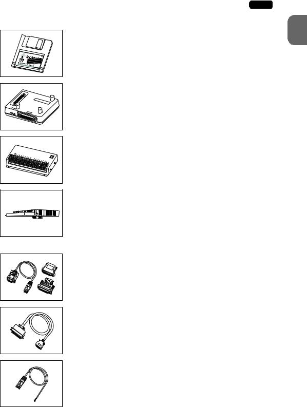
CREC (card recorder)
The card recorder creates a backup copy of screen data or works as an external memory storage system for memory manager and data logging functions.
REC-MCARD (memory card) compliant with JEIDA ver. 4.0
Used with the card recorder when having a backup copy of screen data or saving data on an external medium for memory manager and data
logging functions. |
|
|
SRAM |
256 k, 512 k, 1 |
M, 2 M, 4 Mbyte |
FLASH ROM |
256 k, 512 k, 1 |
M, 2 M, 4 M, 16 Mbyte |
2. Models and Peripheral Equipment |
1-5 |
|
|
M-CARD SFTE (memory card editor)
Application software for editing data stored on a memory card. (Windows98/NT4.0/Me/2000/XP compatible)
|
P |
P |
V |
-M |
|
G |
|
|
|
|
|
|
|
DD |
1 |
2 3 |
|
|
|
|
|
|
GD |
|
V-MDD (ACPU/QnACPU/FXCPU dual port interface)
Add-on connector with two ports, specifically designed for the connector on the MITSUBISHI’s ACPU/QnACPU/FXCPU programmer. Operability can be improved when directly connecting the V7 series to the ACPU/QnACPU/FXCPU programmer.
|
DC24V |
|
|
|
|
|
|
|
|
|
|
|
|
|
|
|
|
|
|
FG |
IN0 |
IN1 |
IN3 |
IN5 |
IN7 |
|
|
|
|
|
|
|
|
|
|
|
|
|
MJ1 |
|
IN2 |
IN4 |
IN9 |
IN11 |
|
|
|
|
|
|
|
|
|
|
|
||||
|
|
IN6 |
IN8 |
IN13 |
IN15 |
|
|
|
|
|
|
|
|
|
|
||||
|
|
|
|
|
IN10 |
IN12 |
IN14 |
|
OUT1 |
OUT3 |
|
|
|
|
|
|
|
||
|
|
|
|
|
|
|
|
COM+ |
OUT0 |
OUT2 |
OUT5 |
OUT7 |
OOUUTT89 |
|
|
|
|
||
|
|
|
|
|
|
|
|
|
|
|
OUT4 |
OUT6 |
COM1 |
OOUUTT1101 |
OUT12 |
OUT14 |
COM2 |
||
|
|
|
|
|
|
|
|
|
|
|
|
|
|
|
|
|
OUT13 |
OUT15 |
|
V-I/O (serial extension I/O)
Used as an external I/O unit for PLC. It has 16 inputs and 16 outputs.
CU-xx [xx: 00 → OPCN-1, 01 → T-LINK, 02 → CC-Link,
03 → Ethernet/FL-net (OPCN-2), 04 → PROFIBUS-DP, 05 → MELSECNET/10] (communication interface unit)
Used for communications with each network. This unit enables connection of multiple V7 series to a single PLC. Since other devices on the same network can be connected, it brings about the reduction in costs of the whole system.
V6-CP (screen data transfer cable) 3 m
Used for connection between the V7 series and a personal computer, or a personal computer and the card recorder (CREC).
V7-PT (printer cable) 2.5 m
Used for connection between the V7 series and a printer.
V6-BCD (barcode reader connection cable) 3 m
Used for connection between the V7 series and a barcode reader.
1
Specifications Hardware
1-6 2. Models and Peripheral Equipment
V6-MLT (multi-link 2 master cable) 3 m
Used for Multi-Link 2 connection between the V7 master station and the V7slave station.
V6-TMP (temperature controller connection cable) 3 m
Used for connection between the V7 series and a temperature controller or a PLC via PLC2Way.
MJ-D25 (MJ-to-D-sub conversion cable) 0.3 m under development
Used for connection between the V7 series and a PLC via PLC2Way.
V7xx-GS [xx: 08 → V708/V708i, 10 → V710/V710i, 12 → V712/V712i]
(protective sheet)
This sheet protects the operation panel surface. (5 sheets/set)
V7xx-GSN10 [xx: 08 → V708/V708i, 10 → V710/V710i, 12 → V712/V712i] (protective sheet)
This anti-glare sheet protects the operation panel surface. (5 sheets/set)
V7-BT (battery for replacement)
Replacement lithium battery for the V7 series.
V708S-FL → V708S/V708iS
V6xxx-FL [xxx: 08C → V708C, 10T → V710T/V710iT,
10S → V710S/V710iS, 12S → V712S/V712iS]
(backlight for replacement)
Replacement backlight parts for the V7 series.
3. System Composition |
1-7 |
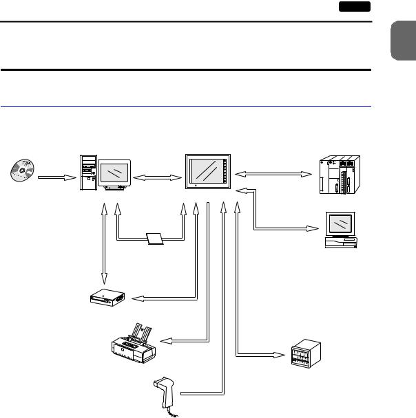
3.System Composition
System Composition of V7 (Standard)
The following illustration shows possible system configurations using the V7 series (standard).
V series |
|
During operation |
|
Panel Editor |
Transferring |
|
|
(Link communication) |
|
||
Creating screens |
screen data |
RS-232C/RS-422 |
|
V6-CP |
|
||
|
|
||
V-SFT |
Personal computer (PC) |
V7 (standard) |
|
|
Link unit |
||
|
During operation |
||
|
|
||
|
|
|
|
|
Transferring screen data |
(Universal serial |
|
|
communication) |
|
|
|
Transferring recipe data |
|
|
|
RS-232C/RS-422 |
|
|
|
Saving sampling data |
|
|
|
etc. |
|
|
|
CompactFlash |
|
Transferring screen data |
Card |
|
CF card |
||
Transferring other data |
||
General-purpose |
||
|
computer |
Transferring screen data
V6-CP Memory manager
Data logging function
CREC cable
Card recorder
CREC
Printer cable
V7-PT
|
Cable |
|
|
V6-TMP |
|
Printer |
|
|
Cable |
Temperature controller, |
|
inverter |
||
V6-BCD |
||
|
||
Barcode reader |
|
1
Specifications Hardware
1-8 3. System Composition
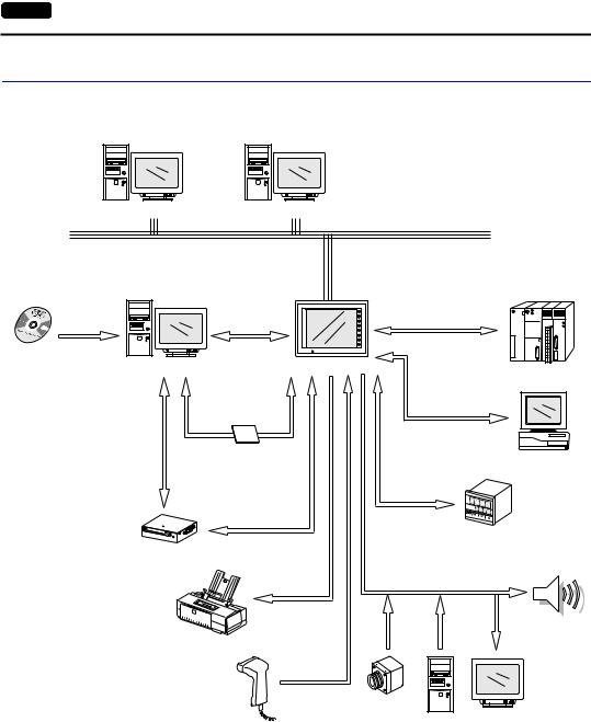
System Composition of V7i (High-performance)
The following illustration shows possible system configurations using the V7i series (high-performance).
Personal computer (PC) |
Personal computer (PC) |
Ethernet
V series |
|
During operation |
|
Panel Editor |
Transferring |
||
(Link communication) |
|||
Creating screens |
screen data |
RS-232C/RS-422 |
|
V6-CP |
|||
|
V-SFT
Personal computer (PC) |
V7i (high-performance) |
|
|
Link unit |
|
|
|
*1 |
During operation |
||
|
Transferring screen data |
|
(Universal serial |
|
|
|
|
communication) |
|
||
|
Transferring recipe data |
|
|
||
|
|
RS-232C/RS-422 |
|
||
|
Saving sampling data |
|
|
||
|
etc. |
|
|
|
|
|
CompactFlash |
|
|
|
|
|
Card |
|
|
|
|
Transferring screen data |
CF card |
|
|
|
General-purpose |
|
|
|
|
||
Transferring other data |
Transferring screen data |
|
|
computer |
|
V6-CP |
Cable |
|
|
||
Memory manager |
|
|
|
||
|
|
|
|
||
|
Data logging function |
V6-TMP |
|
|
|
|
CREC cable |
|
|
|
|
|
|
|
Temperature controller, |
||
Card recorder |
|
|
inverter |
|
|
|
|
|
|
|
|
CREC |
|
|
|
|
|
|
Printer cable |
|
|
|
|
|
|
V7-PT |
|
|
|
|
Printer |
|
|
|
Speaker |
|
|
|
|
(Sound output) |
|
|
|
Cable |
|
|
|
|
|
V6-BCD |
|
|
|
|
|
Video camera |
|
|
|
|
|
(Video input) |
Display |
|
|
|
Barcode reader |
Personal |
|
||
|
computer |
(RGB output) |
|||
|
|
|
|||
(RGB input)
*1 The option unit (EU-xx) is required.

4. Specifications |
1-9 |
4.Specifications
General Specifications
|
|
Model |
V708 |
V710 |
|
V712 |
|||||
|
|
|
|
|
|
|
|
|
|
||
Item |
|
|
DC power supply |
AC power supply |
|
DC power supply |
|
AC power supply |
DC power supply |
||
|
|
|
|
|
|
|
|
|
|
|
|
|
|
Rated Voltage |
24 VDC |
100 - 240 VAC |
|
|
24 VDC |
|
100 - 240 VAC |
24 VDC |
|
|
|
|
|
|
|
|
|
|
|
|
|
|
|
Permissible Range |
24 VDC ±10% |
100 - 240 VAC |
|
|
24 VDC ±10% |
|
100 - 240 VAC |
24 VDC ±10% |
|
|
|
of Voltage |
±10% |
|
|
|
±10% |
||||
|
|
|
|
|
|
|
|
|
|||
|
|
Permissible |
|
|
|
|
|
|
|
|
|
|
|
Momentary Power |
Within 1 ms |
Within 20 ms |
|
|
Within 1 ms |
|
Within 20 ms |
Within 1 ms |
|
Supply |
|
Failure |
|
|
|
|
|
|
|
|
|
|
|
15 W or |
22 W or |
60 VA or less |
|
|
30 W or less |
|
60 VA or less |
30 W or less |
|
|
|
Power Consumption |
V708C |
V708S/iS |
|
|
|
|
|
|
|
Power |
|
(Maximum Rating) |
less |
less |
|
|
|
|
|
|
|
|
|
|
|
|
|
|
|
|
|||
|
|
|
|
|
|
|
|
|
|
|
|
|
|
|
|
For 100 VAC: |
|
|
|
|
For 100 VAC: |
|
|
|
|
|
|
|
|
|
|
|
|
||
|
|
Rush Current |
25 A, 0.7 ms |
16 A, 6 ms |
|
|
30A, 1 ms |
|
16 A, 6 ms |
30 A, 1 ms |
|
|
|
For 200 VAC: |
|
|
|
For 200 VAC: |
|||||
|
|
|
|
|
|
|
|
|
|
||
|
|
|
|
|
32 A, 7 ms |
|
|
|
|
32A, 7 ms |
|
|
|
|
|
|
|
|
|
|
|
|
|
|
|
|
DC external |
AC external |
|
|
DC external |
|
AC external |
DC external |
|
|
|
Withstand Voltage |
terminals to FG: |
terminals to FG: |
|
|
terminals to FG: |
|
terminals to FG: |
terminals to FG: |
|
|
|
500 VAC, |
1500 VAC, |
|
|
500 VAC, |
|
1500 VAC, |
500 VAC, |
||
|
|
|
|
|
|
||||||
|
|
|
1 minute |
|
1 minute |
|
|
1 minute |
|
1 minute |
1 minute |
|
|
|
|
|
|
|
|
||||
Insulation Resistance |
|
|
500 VDC, 10 MΩ or above |
|
|||||||
|
|
|
|
|
|
|
|
|
|
|
|
Environment |
|
Ambient |
|
|
|
|
|
0°C to +50°C |
|
|
|
|
Temperature |
|
|
|
|
|
|
|
|||
|
|
|
|
|
|
|
|
|
|||
|
|
|
|
|
|
|
|
|
|
|
|
|
|
|
|
|
|
|
|
|
|
|
|
|
|
Storage Ambient |
|
|
|
|
|
−10°C to +60°C |
|
|
|
|
|
Temperature |
|
|
|
|
|
|
|
||
|
|
|
|
|
|
|
|
|
|
|
|
|
|
|
|
|
|
|
|||||
Physical |
|
Ambient Humidity |
|
|
85%RH or less (without dew condensation) |
|
|||||
|
|
|
|
|
|
|
|
|
|
|
|
|
Solvent Resistance |
|
|
No cutting oil or organic solvent attached to the unit |
|
||||||
|
|
|
|
|
|||||||
|
|
|
|
|
|
|
|||||
|
|
Atmosphere |
|
|
No corrosive gas or conductive dust |
|
|||||
|
|
|
|
|
|
||||||
Mechanical Working |
Conditions |
Vibration Resistance |
|
Vibration frequency: |
10 to 150 Hz, Acceleration: 9.8 m/s2 (1.0G) |
||||||
|
Peak acceleration: |
147 m/s2 (15G), X, Y, Z: 3 directions six times each |
|||||||||
|
|
|
|
Single amplitude: |
0.075 mm, X, Y, Z: 3 directions for one hour |
||||||
|
|
Shock Resistance |
|
Pulse shape: |
Sine half wave |
|
|
||||
|
|
|
|
|
|
|
|
|
|
|
|
|
|
|
|
|
|
|
|||||
Electrical Working |
Conditions |
Noise Resistance |
|
|
1500Vp-p (pulse width 1 µs, rising time: 1 ns) |
|
|||||
|
|
|
|
|
|
|
|
|
|
||
Static Electricity |
|
|
|
|
|
|
|
|
|
||
|
|
Discharge |
|
|
Compliant with IEC1000-4-2, contact: 6 kV, air: 8 kV |
|
|||||
|
|
Resistance |
|
|
|
|
|
|
|
|
|
|
|
Grounding |
|
|
Grounding resistance: less than 100 Ω |
|
|||||
|
|
|
|
|
|
||||||
Conditions |
|
|
|
Protection structure: |
front panel compliant with IP65 (when using gasket) |
||||||
|
Structure |
|
|
|
rear case: compliant with IP20 |
|
|||||
|
|
|
Form: |
|
in a body |
|
|
||||
|
|
|
|
|
|
|
|||||
|
|
|
|
Mounting procedure: |
inserted in a mounting panel |
|
|||||
|
|
|
|
|
|
|
|
|
|
|
|
Mounting |
|
Cooling System |
|
|
|
|
|
Cooling naturally |
|
|
|
|
|
|
|
|
|
|
|
||||
|
Dimensions |
233 × 178 × 66.1 |
303.8 × 231.0 × 72.0 |
|
326.4 × 259.6 × 72.0 |
||||||
|
|
Weight (kg) |
Unit: approx. 1.5 |
Unit: approx. 2.4 |
|
Unit: approx. 2.7 |
|||||
|
|
W × H × D (mm) |
|
|
|
|
|
|
|
|
|
|
|
|
|
|
|
|
|
||||
|
|
Panel Cut-out (mm) |
220.5 −+00.5 × 165.5 −+00.5 |
289.0 +0.5 |
× 216.2 −+00.5 |
|
313.0 −+00.5 × 246.2 −+00.5 |
||||
|
|
|
|
|
|
|
|
|
|
|
|
Case Color |
|
|
|
|
Black (Munsell N2.0) |
|
|
||||
|
|
|
|
|
|
|
|
|
|||
Material |
|
|
|
|
|
PC/PS resin (Tarflon) |
|
|
|||
|
|
|
|
|
|
|
|
|
|
|
|
1
Specifications Hardware

1-10 4. Specifications
Display Specifications
Model |
V708C |
V708S |
V708iS |
V710T |
V710iT |
V710S |
|
V710iS |
V712S |
V712iS |
|
Item |
|
||||||||||
|
|
|
|
|
|
|
|
|
|
||
|
|
|
|
|
|
|
|
|
|
|
|
Display Device |
STN |
|
|
|
TFT color LCD |
|
|
|
|||
color LCD |
|
|
|
|
|
|
|||||
|
|
|
|
|
|
|
|
|
|
||
|
|
|
|
|
|
|
|
|
|
|
|
Effective Display |
7.7-inch |
8.4-inch |
|
10.4-inch |
|
12.1-inch |
|||||
Area |
|
|
|||||||||
|
|
|
|
|
|
|
|
|
|
||
|
|
|
|
|
|
|
|
|
|
|
|
Colors |
128 colors |
|
|
|
32,768 colors |
|
|
|
|||
+16-color blinks |
|
|
|
+16-color blinks |
|
|
|
||||
|
|
|
|
|
|
|
|||||
|
|
|
|
|
|
|
|
|
|
|
|
Resolution |
640 × 480 |
800 × 600 |
640 × 480 |
|
|
800 × 600 |
|
||||
W × H (dots) |
|
|
|
||||||||
|
|
|
|
|
|
|
|
|
|
||
|
|
|
|
|
|
|
|
|
|
|
|
Dot Pitch |
0.246 × 0.246 |
0.213 × 0.213 |
0.33 × 0.33 |
0.264 × 0.264 |
0.3075 × 0.3075 |
||||||
W × H (mm) |
|||||||||||
|
|
|
|
|
|
|
|
|
|
||
|
|
|
|
|
|
||||||
Brightness (cd/m2) |
200 |
350 |
350 |
280 |
350 |
||||||
Contrast Ratio |
25 : 1 |
250 : 1 |
300 : 1 |
300 : 1 |
350 : 1 |
||||||
|
|
|
|
|
|
|
|
|
|
|
|
Angle of Vertical |
+40, −30 |
+35, −55 |
+45, −55 |
+35, −45 |
+40, −45 |
||||||
Visibility (°) |
|||||||||||
|
|
|
|
|
|
|
|
|
|
||
|
|
|
|
|
|
|
|
|
|
|
|
Angle of Horizontal |
±50 |
±50 |
±70 |
±50 |
±55 |
||||||
Visibility (°) |
|||||||||||
|
|
|
|
|
|
|
|
|
|
||
|
|
|
|
|
|
|
|
|
|
||
Backlight |
|
Cold cathode rectifier (exchangeable by users) |
|
|
|||||||
|
|
|
|
|
|
|
|
|
|
|
|
Backlight Average |
Approx. |
|
|
|
Approx. 50,000 h |
|
|
|
|||
Life *1 |
40,000 h |
|
|
|
|
|
|
||||
|
|
|
|
|
|
|
|
|
|||
Backlight |
|
|
Always ON, random setting |
|
|
|
|||||
Auto OFF Function |
|
|
|
|
|
||||||
|
|
|
|
|
|
|
|
|
|
||
|
|
|
|
|
|
|
|
|
|
|
|
Contrast Adjustment |
Provided *2 |
|
|
|
Not provided |
|
|
|
|||
Brightness |
Not provided |
|
|
|
3 levels *2 |
|
|
||||
Adjustment |
|
|
|
|
|
||||||
|
|
|
|
|
|
|
|
|
|
||
|
|
|
|
|
|
|
|
|
|
|
|
Surface Sheet |
|
|
Material: Polycarbonate, 0.3 mm thick |
|
|
|
|||||
|
|
|
|
|
|
|
|||||
POWER Lamp |
|
|
ON when the power is supplied |
|
|
|
|||||
|
|
|
|
|
|
|
|
|
|
|
|
*1 When the normal temperature is 25°C, and the surface luminance of the display is 50% of the initial setting.
*2 Adjustable with function switches
Touch Panel Specifications
Item |
Specifications |
|
|
Method |
Analog resistance film type |
|
|
Switch Resolution |
1024 (W) × 1024 (H) |
|
|
Mechanical Life |
One million activations or more |
|
|
Surface Treatment |
Hard-coated, anti-glare treatment 5% |
|
|

4. Specifications |
1-11 |
|
|
Function Switch Specifications
Item |
Specifications |
|
|
Number of Switches |
8 |
|
|
Method |
Pressure sensitive |
|
|
Mechanical Life |
One million activations or more |
|
|
Interface Specifications
Item |
|
Specifications |
|
|
|
Serial Interface for PLC |
RS-232C, RS-422/485 |
|
Connection |
Asynchronous type |
|
(D-sub 25-pin, female) |
Data length: |
7, 8 bits |
|
Parity: |
even, odd, none |
|
Stop bit: |
1, 2 bits |
|
Baud rate: |
4800, 9600, 19200, 38400, 57600, 76800, 115 kbps |
|
|
|
Serial Interface 1, 2 for Screen |
RS-232C, RS-422/485 (2-wire connection) |
|
Data Transfer/External |
CREC, Barcode, V-I/O, Multi-link 2, |
|
Connection |
Temperature control network/PLC2Way, V-link, etc. |
|
(Modular jack, 8-pin) |
|
|
|
|
|
Printer Interface for Printer |
Compliant with Centronics, half-pitch 36-pin |
|
Connection |
NEC: |
PR201 |
|
EPSON: |
ESC/P-J84, ESC/P super function, ESC/P24-J84 |
|
CBM292/293 printer *1, HP PCL Level 3 |
|
|
Barcode printer MR400 |
|
|
|
|
CF Card Interface |
Compliant with CompactFlashTM |
|
10BASE-T for Ethernet |
Compliant with IEEE802.3 |
|
Connection |
Baud rate: |
10 Mbps |
(Standard with V7i) |
Cables: |
100 Ω unshielded twist-pair, |
|
|
Category 5, maximum length = 100 m |
|
|
|
*1 The CBM292/293 printer cannot print screen hard copies.
Clock and Backup Memory Specifications
Item |
Specifications |
|
|
Battery Specification |
Coin-type lithium primary cell |
|
|
|
Battery type: Sanyo CR2450-CN21 |
|
|
Backup Memory |
SRAM 64 kbyte |
|
|
Backup Time Period |
5 years (ambient temperature at 25°C) |
|
|
Battery Voltage Drop Detection |
Provided (internal memory allocated) |
|
|
Calendar Accuracy |
Monthly deviation ±90 sec (ambient temperature at 25°C) |
|
|
1
Specifications Hardware

1-12 4. Specifications
Drawing Environment
Item |
|
Specifications |
|
|
|
Drawing Method |
Exclusive drawing software |
|
|
|
|
Drawing Tool |
Name of exclusive drawing software: |
V-SFT (Ver. 2.00 and later) |
|
Personal computer: |
Pentium II 450 MHz or above recommended |
|
OS: |
Windows98/Me/NT Ver. 4.0/2000/XP |
|
Capacity of hard disk required: |
Free space of approx. 460 Mbyte or more |
|
|
(For minimum installation: approx. 105 Mbyte) |
|
Display: |
Resolution 800 × 600 or above recommended |
|
|
|
Display Function Specifications
Item |
|
|
|
Specifications |
|
|
|
||
|
|
|
|
|
|
|
|
|
|
Display Language* |
Japanese |
|
English/ |
Chinese |
|
Chinese |
|
Korean |
|
|
|
|
|
European |
|
|
(Simplified) |
|
|
Characters |
1/4-size |
ANK code |
|
Latin 1 |
ASCII code |
|
ASCII code |
|
ASCII code |
|
1-byte |
|
|
|
|||||
|
|
|
|
|
|
|
|
|
|
|
2-byte |
JIS #1, #2 level |
|
−−−− |
Chinese |
|
Chinese |
|
Hangul |
|
16-dot |
|
|
(simplified) |
|
(without Kanji) |
|||
|
|
|
|
|
|
|
|||
|
2-byte |
JIS #1 level |
|
−−−− |
−−−− |
|
−−−− |
|
−−−− |
|
32-dot |
|
|
|
|||||
|
|
|
|
|
|
|
|
|
|
Character Size |
1/4-size: |
8 × 8 dots |
|
|
|
|
|
||
|
|
1-byte: |
8 × 16 dots |
|
|
|
|
|
|
|
|
2-byte: |
16 × 16 dots or 32 × 32 dots |
|
|
|
|||
|
|
Enlarge: |
W: 1 to 8 times, H: 1 to 8 times |
|
|
|
|||
|
|
|
|
|
|
|
|||
Number of |
Resolution |
|
640 × 480 |
|
800 × 600 |
||||
Displayable |
|
|
|
|
|
|
|
|
|
1/4-size |
|
80 columns × 60 lines |
|
100 columns × 75 lines |
|||||
Characters |
|
|
|||||||
|
|
|
|
|
|
|
|
||
1-byte |
|
80 columns × 30 lines |
|
100 columns × 37 lines |
|||||
|
|
|
|
||||||
|
|
|
|
|
|
|
|
||
|
|
2-byte |
|
40 columns × 30 lines |
|
50 columns |
× 37 lines |
||
|
|
|
|
|
|
|
|
||
Characters |
Display properties: |
Normal, reverse, blink, bold, shadow |
|
||||||
Properties |
Colors: |
32,768 colors + blink 16 colors (V708C: 128 colors + blink 16 colors) |
|||||||
|
|
|
|
||||||
Graphics |
Lines: |
Line, continuous line, box, parallelogram, polygon |
|
||||||
|
|
Circles: |
Circle, arc, sector, ellipse, elliptical arc |
|
|||||
|
|
Others: |
Tile patterns |
|
|
|
|
|
|
|
|
|
|
||||||
Graphic Properties |
Line types: |
6 (thin, thick, dot, chain, broken, two-dot chain) |
|
||||||
|
|
Tile patterns: |
16 (incl. user-definable 8 patterns) |
|
|
|
|||
|
|
Display properties: Normal, reverse, blink |
|
|
|
||||
|
|
Colors: |
32,768 colors + blink 16 colors (V708C: 128 colors + blink 16 colors) |
||||||
|
|
Color selection: |
Foreground, background, boundary (line) |
|
|||||
|
|
|
|
|
|
|
|
|
|
* Refer to the Reference Manual (Operation) for HK fonts.

4. Specifications |
1-13 |
|
|
Function Performance Specifications
|
|
Item |
|
Specifications |
|
|
|
|
|
|
|
Screens |
Max. 1024 |
|
|
||
|
|
|
|||
Screen Memory |
Flash memory: Appox. 4,992 kbyte (varies depending on the font) |
||||
|
|
|
|
|
|
Switches |
768 per screen |
|
|
||
|
|
|
|
||
Switch Actions |
Set, reset, momentary, alternate, to light |
|
|||
|
|
|
(Possible to press a function switch and a display switch at the same time) |
||
|
|
|
|
||
Lamps |
Reverse, blink, exchange of graphics |
|
|||
|
|
|
768 per screen |
|
|
|
|
|
|
||
Graphs |
Pie, bar, panel meter and closed area graph: |
No limitation within 256 kbyte |
|||
|
|
|
|
|
per screen *1 |
|
|
|
Statistics and trend graphs: |
Max. 256 per layer *2 |
|
Setting |
|
Numerical Data Display |
No limitation within 256 kbyte per screen *1 |
|
|
|
Character Display |
No limitation within 256 kbyte per screen *1 |
|
||
|
|
|
|||
Data |
Message Display |
Resolution: |
640 × 480, max. 80 characters (1-byte) |
||
|
|
800 × 600, max. 100 characters (1-byte) |
|||
|
|
|
No limitation within 256 kbyte per screen *1 |
|
|
Sampling |
Sampling display of buffer data |
|
|||
|
|
|
(Constant sample, bit synchronize, bit sample, relay sample, alarm function) |
||
|
|
|
|
||
Graphic Library |
Max. 1024 |
|
|
||
|
|
|
|
||
Multi-Overlaps |
Max. 1024 |
|
|
||
|
|
|
|
||
Data Blocks |
Max. 2560 |
|
|
||
|
|
|
|
||
Messages |
Max. 6144 lines |
|
|
||
|
|
|
|
||
Patterns |
Max. 1024 |
|
|
||
|
|
|
|
||
Macro Blocks |
Max. 1024 |
|
|
||
|
|
|
|
||
Page Blocks |
Max. 1024 |
|
|
||
|
|
|
|
||
Direct Blocks |
Max. 1024 |
|
|
||
|
|
|
|
||
Screen Blocks |
Max. 1024 |
|
|
||
|
|
|
|
||
Data Sheets |
Max. 1024 |
|
|
||
|
|
|
|
||
Screen Library |
Max. 1024 |
|
|
||
|
|
|
|
||
Animation (Frames) |
Max. 1023 |
|
|
||
|
|
|
|
||
Temperature Control Network/ |
Max. 32 |
|
|
||
PLC2Way Table |
|
|
|
||
|
|
|
|||
Time Display |
Time display function: provided |
|
|||
|
|
|
|||
Hard Copy |
Screen hard copy function: provided |
|
|||
|
|
||||
Buzzer |
Buzzer: provided, 2 sounds (short beep, long beep) |
||||
|
|
|
|||
Auto OFF Function |
Always ON, random setting |
|
|||
|
|
|
|||
Self-diagnostic Function |
Switch self-test function |
|
|||
|
|
|
Communication parameter setting check function |
||
|
|
|
Communication check function |
|
|
|
|
|
|
|
|
*1 The number of setting memory locations is limited to 1024 per screen. *2 Layer: 4 per screen (base + 3 overlaps)
1
Specifications Hardware
Loading...