


 Loading...
TM-H5000II series
Operator’s Manual
Using this online operator’s guide
The words on the left side of this screen are bookmarks for all the topics in this guide.
Use the scroll bar next to the bookmarks to find any topic you want. Click a bookmark to instantly jump to its topic. (If you wish, you can increase the size of the bookmark area by dragging the dividing bar to the right.)
Use the scroll bar on the right side of this screen to move through the text.
Use the zoom tools to magnify or reduce the page display.
Click the Find button if you want to search for a particular term. (However, using the bookmarks is usually quicker.)
Complete online documentation for Acrobat Reader is located in the Help directory for Acrobat Reader.
Return to main menu
hybrid printer
TM-H5000II series
Operator’s Manual
MICR Option Included
400826500
Printed in Japan
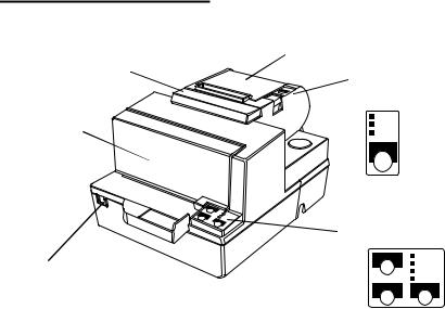
Printer Parts and Labels
Paper roll cover
Auto-cutter cover
Paper roll control panel
|
POWER |
Front cover |
ERROR |
PAPER |
|
|
OUT |
|
FEED |
Slip paper control panel
On/Off switch
FORWARD |
POWER |
|
ERROR |
|
RELEASE |
|
SLIP |
REVERSE RELEASE
Caution Labels
 CAUTION:
Thermal head and printer head are hot.
 ATTENTION:
La téte thermique et la téte d’imprimante sont chaudes.
 VORSICHT:
Der Thermalkopf und der Druckerkopf sind heiß.
 CAUTION:
Caution labels for drawer kick-out and display module connectors.
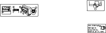
Instruction Labels
2
1
Label affixed on the document table
Ribbon installation label inside
front cover
Label inside paper |
Label inside |
roll cover |
cutter section |
 CAUTION:
Caution labels for drawer kick-out and display module connectors.
Printerd in Japan

Quick Reference
This Quick Reference will direct you to key areas of this Operator’s Manual. For a complete listing of topics, see the Contents.
Printer Parts and Labels |
inside front cover |
Ordering Paper and Ribbons |
page viii |
Where to order paper and ribbons. |
|
Setting Up the Printer |
page 1-1 |
How to set up the printer. |
|
Installing and Replacing Paper |
page 1-10 |
How to load or change the roll paper. |
|
Validating and Verifying Checks |
page 2-5 |
How to validate and verify checks using the optional Magnetic Ink Character Recognition (MICR) Reader.
Solving Problems |
page 3-1 |
How to correct problems.
i

All rights reserved. No part of this publication may be reproduced, stored in a retrieval system, or transmitted in any form or by any means, electronic, mechanical, photocopying, recording, or otherwise, without the prior written permission of Seiko Epson Corporation. No patent liability is assumed with respect to the use of the information contained herein. While every precaution has been taken in the preparation of this book, Seiko Epson Corporation assumes no responsibility for errors or omissions. Neither is any liability assumed for damages resulting from the use of the information contained herein.
Neither Seiko Epson Corporation nor its affiliates shall be liable to the purchaser of this product or third parties for damages, losses, costs, or expenses incurred by purchaser or third parties as a result of: accident, misuse, or abuse of this product or unauthorized modifications, repairs, or alterations to this product, or (excluding the U.S.) failure to strictly comply with Seiko Epson Corporation’s operating and maintenance instructions.
Seiko Epson Corporation shall not be liable against any damages or problems arising from the use of any options or any consumable products other than those designated as Original Epson Products or Epson Approved Products by Seiko Epson Corporation.
EPSON is a registered trademark of Seiko Epson Corporation. ESC/POS is a registered trademark of Seiko Epson Corporation.
NOTICE: The contents of this manual are subject to change without notice.
Copyright © 1997 by Seiko Epson Corporation, Nagano, Japan.
ii

FCC CLASS A
FCC Compliance Statement
For American Users
This equipment has been tested and found to comply with the limits for a Class A digital device, pursuant to Part 15 of the FCC Rules. These limits are designed to provide reasonable protection against harmful interference when the equipment is operated in a commercial environment.
This equipment generates, uses, and can radiate radio frequency energy and, if not installed and used in accordance with the instruction manual, may cause harmful interference to radio communications. Operation of this equipment in a residential area is likely to cause harmful interference, in which case the user will be required to correct the interference at his own expense.
WARNING
The connection of a non-shielded printer interface cable to this printer will invalidate the FCC Verification of this device and may cause interference levels which exceed the limits established by the FCC for this equipment.
You are cautioned that changes or modifications not expressly approved by the party responsible for compliance could void your authority to operate the equipment.
FOR CANADIAN USERS
This Class A digital apparatus meets all requirements of the Canadian InterferenceCausing Equipment Regulations.
Cet appareil numérique de la classe A respecte toutes les exigenves du Règlement sur le matériel brouileur du Canada.
GEREÄUSCHPEGEL
Gemäß der Dritten Verordnung zum Gerätesicherheitsgesetz (Maschinenlärminformations- Verordnung-3. GSGV) ist der arbeitsplatzbezogene Geräusch-Emissionswert kleiner als 70 dB(A) (basierend auf ISO 7779).
iii

DECLARATION OF CONFORMITY
Product Name: Printer
Model Name: M128C
This printer conforms to the following Directives and Norms:
Directive 89/336/EEC
EN 55022 (1987 and 1994 2nd/1995) Class B
EN 50082-1 (1992)
IEC 801-2 (1991)
IEC 801-3 (1984)
IEC 801-4 (1988)
Directive 90/384/EEC
EN45501: (1992)
iv

EMI and Safety Standards Applied
The following standards are applied only to the printers that are so labeled. (EMC is tested using the EPSON PS-170 power supply)
Europe: |
CE marking |
|
EN55022 |
|
EN50082-1 |
|
EN45501 |
|
Safety Standard: TÜV |
North America: |
EMI: FCC Class A |
|
Safety standards: UL 1950-2TH-D3 |
|
C-UL |
Japan: |
EMI: VCCI Class 1 |
China (the People’s Republic of China): |
|
|
Safety standards:GB4943-1995 |
Oceania: |
EMI: AS/NZS 3548 class B |
v

About This Manual
Setting Up and Using
Chapter 1 contains information on unpacking the printer, setting it up, setting the DIP switches, and adjusting the paper near end sensor.
Chapter 2 contains information on using the printer.
Chapter 3 contains troubleshooting information.
Reference
Chapter 4 contains specifications
Appendix A tells how to change the DIP switch and paper near end settings, and Appendix B lists the EPSON Sales Subsidiaries and their addresses.
Warnings, Cautions, and Notes
 WARNING:
Warnings must be followed carefully to avoid serious bodily injury.
 CAUTION:
Cautions must be observed to avoid minor injury to yourself or damage to your equipment.
Note:
Notes have important information and useful tips on the operation of your printer.
vi
Introduction
Features
The TM-H5000II and TM-H5000IIP are high-quality POS printers that can print on slip and receipt paper (paper roll). The printers have the following features:
Slip Section
Wide slip paper capability (maximum characters per line: 88 with 7 × 9 font).
Copy printing is possible.
High throughput using bidirectional, minimum distance printing.
Optional Magnetic Ink Character Recognition (MICR) reader that enables the printer to perform consecutive reading and processing of MICR characters and printing endorsements.
Receipt Section
High speed printing with collective printing.
The standard auto-cutter provides easy user operation.
Ladder bar code printing is possible by using a bar code command.
New paper handling enables easy paper roll loading.
Both Receipt and Slip
Standard EPSON customer display series connector (DM-D102-012/DM-D203- 012) (Available only for the serial interface model).
Selectable receive buffer size (45 bytes or 4K bytes).
Command protocol based on the ECS/POS® standard.
Automatic Status Back (ASB) function that automatically transmits changes in the printer status.
Available non-volatile bit image buffer size (384K bytes)
vii Introduction

Options and Accessories
Direct connection display modules, DM-D102-012 and DM-D203-012 (Available only for the serial interface model)
EPSON power supply unit, PS-170
EPSON ribbon cassette, ERC-31(P) / ERC-31(B)
Front extension table, WT-5000
MICR feed roller cleaning sheet (adhesive type)
Part name: |
Sheet-roller cleaning-A |
Part code: |
Epson 1038046 |
For cleaning the MICR head, use the following cleaning sheet that is commercially available:
Supplier name: |
PRESAT brand (KIC) |
Part name: |
CHECK READER CLEANING CARD or |
|
equivalent |
Ordering Paper and Supplies
Thermal paper can be ordered from the supplier in your area.
Specified Thermal Paper: NTP080-80
In Japan: |
Nakagawa Seisakujo |
|
2-5-21 Nishiki-Cho Warabi-Shi |
|
Saitama-Ken 335 Japan |
|
Tel: (048) 444-8211 |
|
Fax: (048) 443-6652 |
In U.S.A.: |
Nakagawa Mfg (USA) Inc. |
|
2305 Lincoln Avenue |
|
Hayward, CA 94545 USA |
Introduction viii

|
Tel: (510) 782-0197 |
|
Fax: (510) 782-7124 |
In Europe: |
Nakagawa Mfg (Europe) GmbH. |
|
Krützpoort 16, 47804 |
|
Krefeld, Germany |
|
Tel: 02151-711051 |
|
Fax: 02151-713293 |
In Southeast Asia: |
N.A.K. Mfg (Malaysia) SDN BHD |
|
Lot 19-11, Bersatu Industrial Complexs, |
|
Jalan Satu, Kaw Per. Cheras Jaya,. |
|
Balakong Industrial Area, 43200 Cheras. |
|
Selangor Darul Ehsan, Malaysia |
|
Tel: 03-9047896, 9047900, 9047691 |
|
Fax: 03-9047889 |
Other Qualified Suppliers for Thermal Paper
The following suppliers sell thermal paper that may be used if desired. Contact each company for information.
Original paper: |
TF50KS-E |
|
Nippon Paper Industry Co., Ltd. |
|
1-12-1, Yuraku-Cho, Chiyoda-Ku |
|
Tokyo 100 Japan |
|
Tel: 03-3218-8000 |
|
Fax: 03-3216-1375 |
Original paper: |
PD 160R |
|
New Oji Paper Mfg. Co., Ltd. |
|
7-5 Ginza 4-Chome Chuo-Ku |
|
Tokyo 104 Japan |
|
Tel: 03-3563-4800 |
|
Fax: 03-3563-1136 |
ix Introduction

Original paper: |
AF50KS-E |
|
Jujo Thermal Oy (Finland) |
|
P.O. Box 92 FIN27501 Kauttua Finland |
|
Tel: 38-3932900 |
|
Fax: 38-3932419 |
Original paper: |
P350(F380) |
|
Kanzaki Specialty Papers, Inc. |
|
1500 Main Street |
|
Spring field, MA 01115 U.S.A. |
|
Tel: (413) 736-3216 |
|
Fax: (413) 734-5101 |
Ordering Ribbon Cassettes
The TM-H5000II series printer uses a long-lasting ribbon cassette in the slip section. To order ribbon cassettes, contact your dealer or your local affiliate. See Appendix B for a list of EPSON subsidiaries with their addresses and telephone numbers.
Introduction x

Contents
Quick Reference. . . . . . . . . . . . . . . . . . . . . . . . . . . . . . . . . . . . . . . . . . . . . . . . . . . . . . . . i Introduction . . . . . . . . . . . . . . . . . . . . . . . . . . . . . . . . . . . . . . . . . . . . . . . . . . . . . . . . . . . vii
Chapter 1 Setting Up the Printer
Unpacking . . . . . . . . . . . . . . . . . . . . . . . . . . . . . . . . . . . . . . . . . . . . . . . . . . . . . . . . . . . . 1-1 Removing the protective material . . . . . . . . . . . . . . . . . . . . . . . . . . . . . . . . . . . . 1-2 Connecting the Cables . . . . . . . . . . . . . . . . . . . . . . . . . . . . . . . . . . . . . . . . . . . . . . . . . . 1-3 Installing or Replacing the Paper Roll . . . . . . . . . . . . . . . . . . . . . . . . . . . . . . . . . . . . . 1-10 Installing the Ribbon Cassette . . . . . . . . . . . . . . . . . . . . . . . . . . . . . . . . . . . . . . . . . . . 1-13 Using the Power Switch Cover . . . . . . . . . . . . . . . . . . . . . . . . . . . . . . . . . . . . . . . . . . . 1-15 Self Test . . . . . . . . . . . . . . . . . . . . . . . . . . . . . . . . . . . . . . . . . . . . . . . . . . . . . . . . . . . . . . 1-15 Running the self test with a paper roll . . . . . . . . . . . . . . . . . . . . . . . . . . . . . . . . 1-15 Running the self test with slip paper . . . . . . . . . . . . . . . . . . . . . . . . . . . . . . . . . . 1-16 Adjustments and Settings . . . . . . . . . . . . . . . . . . . . . . . . . . . . . . . . . . . . . . . . . . . . . . . 1-17
Chapter 2 Using the Printer
Operating the Control Panels . . . . . . . . . . . . . . . . . . . . . . . . . . . . . . . . . . . . . . . . . . . . 2-1 Paper Roll Control Panel . . . . . . . . . . . . . . . . . . . . . . . . . . . . . . . . . . . . . . . . . . . . 2-1 Slip Control Panel . . . . . . . . . . . . . . . . . . . . . . . . . . . . . . . . . . . . . . . . . . . . . . . . . . 2-1 Indicator lights . . . . . . . . . . . . . . . . . . . . . . . . . . . . . . . . . . . . . . . . . . . . . . . . . . . . 2-2 Slip Paper Handling . . . . . . . . . . . . . . . . . . . . . . . . . . . . . . . . . . . . . . . . . . . . . . . . . . . . 2-3 Using the MICR Reader (Option) . . . . . . . . . . . . . . . . . . . . . . . . . . . . . . . . . . . . . . . . 2-5 Reading MICR characters on personal checks . . . . . . . . . . . . . . . . . . . . . . . . . . 2-5
Chapter 3 Troubleshooting
Troubleshooting . . . . . . . . . . . . . . . . . . . . . . . . . . . . . . . . . . . . . . . . . . . . . . . . . . . . . . . |
3-1 |
General problems . . . . . . . . . . . . . . . . . . . . . . . . . . . . . . . . . . . . . . . . . . . . . . . . . . |
3-1 |
Printing problems . . . . . . . . . . . . . . . . . . . . . . . . . . . . . . . . . . . . . . . . . . . . . . . . . . |
3-1 |
Cleaning the paper roll print head . . . . . . . . . . . . . . . . . . . . . . . . . . . . . . . . . . . |
3-3 |
Paper handling problems . . . . . . . . . . . . . . . . . . . . . . . . . . . . . . . . . . . . . . . . . . . |
3-4 |
Auto cutter problems . . . . . . . . . . . . . . . . . . . . . . . . . . . . . . . . . . . . . . . . . . . . . . . |
3-6 |
Cleaning the Optional MICR Mechanism . . . . . . . . . . . . . . . . . . . . . . . . . . . . . . . . . |
3-7 |
Hexadecimal Dump . . . . . . . . . . . . . . . . . . . . . . . . . . . . . . . . . . . . . . . . . . . . . . . . . . . . |
3-10 |
xi

Chapter 4 Reference Information
Printing Specifications . . . . . . . . . . . . . . . . . . . . . . . . . . . . . . . . . . . . . . . . . . . . . . . . . . 4-1
Slip Paper . . . . . . . . . . . . . . . . . . . . . . . . . . . . . . . . . . . . . . . . . . . . . . . . . . . . . . . . . 4-1
Receipt Paper . . . . . . . . . . . . . . . . . . . . . . . . . . . . . . . . . . . . . . . . . . . . . . . . . . . . . 4-2
Ribbon Specifications . . . . . . . . . . . . . . . . . . . . . . . . . . . . . . . . . . . . . . . . . . . . . . . . . . . 4-4
MICR Reader (Option) . . . . . . . . . . . . . . . . . . . . . . . . . . . . . . . . . . . . . . . . . . . . . . . . . 4-4
Paper Specifications . . . . . . . . . . . . . . . . . . . . . . . . . . . . . . . . . . . . . . . . . . . . . . . . . . . . 4-5
Electrical Characteristics . . . . . . . . . . . . . . . . . . . . . . . . . . . . . . . . . . . . . . . . . . . . . . . . 4-9
Reliability . . . . . . . . . . . . . . . . . . . . . . . . . . . . . . . . . . . . . . . . . . . . . . . . . . . . . . . . . . . . . 4-10
Environmental Conditions . . . . . . . . . . . . . . . . . . . . . . . . . . . . . . . . . . . . . . . . . . . . . . 4-11
Appendix A DIP Switch and Paper Near End Settings
Appendix B EPSON Sales Subsidiaries
xii
Chapter 1
Setting Up the Printer
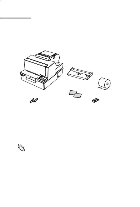
Unpacking
Your printer box should include these items. If any items are damaged or missing, please contact your dealer for assistance.
Ribbon
Paper roll
Hexagonal |
|
Switch |
|
||
lock screws |
|
cover |
These screws are used |
|
|
only for the serial interface |
|
|
(They are not always included.) |
|
|
See the note on page 1-4 for information about the hexagonal lock screws.
Note:
When you lift the printer, be sure to hold the bottom of the printer to prevent damage.
Setting Up the Printer 1-1

Removing the protective material
1. Open the printer by pulling up on the tab on the front cover.
Tab
2. Remove the two dampers from the printer as shown below.
3.Store the dampers with the other packing materials and use them when transporting your printer.
1-2 Setting Up the Printer
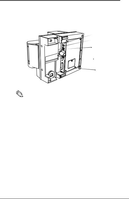
Connecting the Cables and Grounding the Printer
You can connect up to five cables to the printer. They all connect to the connector panel on the bottom of the printer, which is shown below:
Grounding screw
Power supply
Drawer kick-out (See note below)

 Display module
Interface |
Note:
There are caution labels beside the drawer kick-out connector and the display module connector.
Depending on the interface installed, the interface connector on your printer may look different from the one illustrated.
The display module connector of the printer can be used only for the serial interface.
Before connecting any of the cables, make sure that both the printer and the computer are turned off.
Connecting the computer
You need an appropriate interface cable.
1.Plug the cable connector securely into the printer’s interface connector.
Setting Up the Printer 1-3
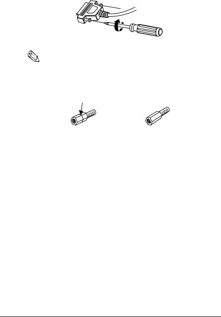
2. Tighten the screws on both sides of the cable connector.
Note:
Your printer has inch-type hexagonal lock screws installed. If your interface cable requires millimeter-type screws, replace the inch-type screws with the enclosed millimeter-type screws using a hex screwdriver (5 mm).
Inch screw |
Millimeter screw |
3. Attach the other end of the cable to the computer.
1-4 Setting Up the Printer
Connecting the Drawer
 WARNING:
Use a drawer that matches the printer specification. Using an improper drawer may damage the drawer as well as the printer.
 CAUTION:
Do not connect a telephone line to the drawer kick-out connector; otherwise the printer and the telephone line may be damaged.
Plug the drawer cable into the drawer kick-out connector on the bottom of the printer next to the power supply connector.
Setting Up the Printer 1-5
Loading...