


4056
4
4
0
0
5
5
1
1
/
/
4
4
0
0
5
5
1
1
N
N
p
p
l
l
u
u
s
s
4
4
0
0
5
5
6
6
/
/
4
4
0
0
5
5
6
6
N
N
p
p
l
l
u
u
s
s
U
U
s
s
e
e
r
r
M
M
a
a
n
n
u
u
a
a
l
l
Rev. 002

ii
Compuprint Information
Thanks
for choosing the
4051/4051N
plus or the
/
4056/4056N plus
printer.
Your printer is a reliable working equipment that will be very useful in your daily job.
Our printer have been designed to be compact and respectful of the work environment. They offer
a wide range of features and multiple functions that confirm the high t echnolog ical level reached
by the Compuprint S.p.A.
To maintain these printing performances unchanged in the long run
,
Compuprint
has
developed specific consumable accessories for each printer type (for example: ribbon cartridges for
dot matrix printers, toner and OPC cartridges for laser printers, bubble ink jet cartridges for
inkjet printers) that assure an excellent operat ion wit h h ig h prin t in g qu alit y level reliabilit y.
Compuprint
recommends to use only its original consumables with original packaging
(identified by its holographic label). In this way, a proper use of the printer at quality level
unreliability stated in the product characteristics can be assured. All typical usage problems
related to not certified consumables may be avoided, such as an overall quality print level
degradation and, often, the reduction of the product life due to the fact that the proper print
heads working conditions, OPC cartridge and other printer parts are not assured.
Moreover
,
Compuprint
does not only certify its consumables in terms of working conditions but
also carefully controls their compliance with the international standard rules concerning:
•
no cancerous materials;
•
no flammability of the plastic materials;
•
other standards
Compuprint
warns the customers not to use products for which the compliance to this safety
rules are not warranted.
Finally seek your dealer or contact a
Compuprint
office and be sure that are provided you the
original
Compuprint
consumables.
iii
S
S
a
a
f
f
e
e
t
t
y
y
I
I
n
n
f
f
o
o
r
r
m
m
a
a
t
t
i
i
o
o
n
n
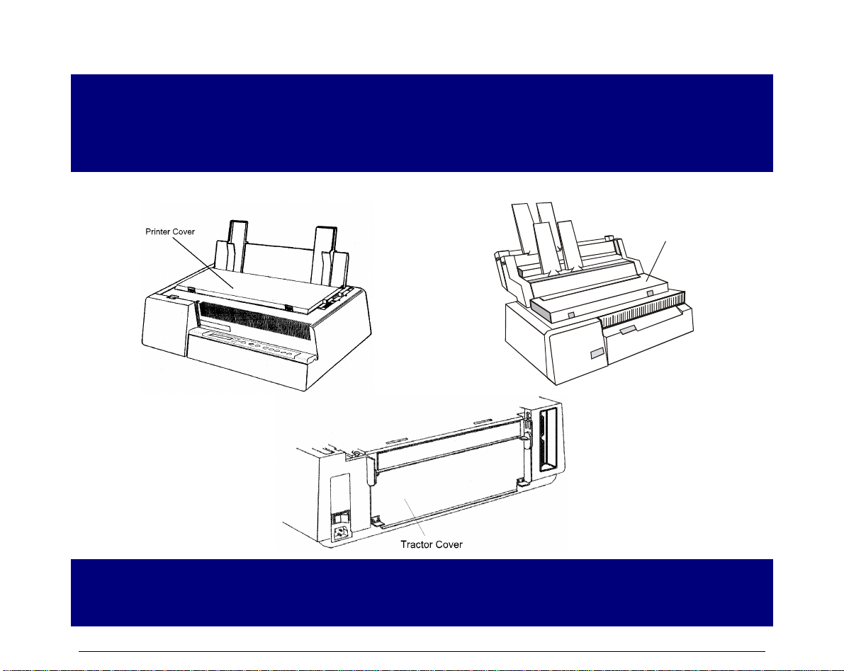
Never remove any printer cover unless it is necessary for the installation of a printer accessory
and expressly described in this manual.
Please retain the printer covers in a safe place because they should be reinstalled if you decide
to remove any printer.
The following areas of the printer should be covered for safety reasons:
Front Cover
(AS F )
The above openings must always be protected with their cover when the
corresponding option is not installed. Do not touch inside and do not insert any object
into these openings or into the gears.

iv
F
F
C
C
C
C
N
N
o
o
t
t
e
e
s
s
This equipment ha s bee n tested and found to com ply with the li mits for a Cla ss B digital devi ce, pursuant to Part
15 of the FCC Rules. These limits are designed to provide reasonable protection against harmful interference when
the equipment is operated in a commercial environment. This equipment generates, uses and can radiate radio
frequency energy and, if not installed and used in accordance with the instruction manual, may cause harmful
interference to radio communications. However, there is no guarantee that interference will not occur in a
particular installation. If this equipment does cause harmful interference to radio or television reception, which
can be determined by turning the equipment off and on, the user is encouraged to try to correct the interference by
one or more of the following measures:
• Reorient or relocate the receiving antenna.
• Increase the separation between the equipment and the receiver to outlets on different circuits.
• Consult the dealer or an experienced radio/TV technician for help.
Changes or modifications not expressly approved by the party responsible for compliance could avoid the user's
authority to operate the equipment. The use of a non-shielded interface cable with the referenced device is
prohibited. The length of the parallel interface cable must be 3 meters (10 feet) or less. The length of the serial
interface cable must be 15 meters (50 feet) or less.
C
C
a
a
n
n
a
a
d
d
i
i
a
a
n
n
D
D
.
.
O
O
.
.
C
C
.
.
R
R
a
a
d
d
i
i
o
o
I
I
n
n
t
t
e
e
r
r
f
f
e
e
r
r
e
e
n
n
c
c
e
e
R
R
e
e
g
g
u
u
l
l
a
a
t
t
i
i
o
o
n
n
This digital apparatus does not exceed the Class B limits for radio noise emission from digital apparatus as set out
in the radio interference regulations of the Canadian Department of Communications.
Le présent appareil numérique n'émet pas de bruits radioélectriques dépassant les limites applicables aux
appareils numériques de classe A prescrites dans le règlement sur le brouillage radioélectrique édicté par le
ministère des communications du Canada
.
E
E
E
E
C
C
R
R
e
e
g
g
u
u
l
l
a
a
t
t
i
i
o
o
n
n
s
s
This equipment conforms to the EEC Directive 89/392 (the sound pressure, me asured according to ISO 7779, does
not exceed 70 dBA).

v
T
T
a
a
b
b
l
l
e
e
o
o
f
f
C
C
o
o
n
n
t
t
e
e
n
n
t
t
s
s
Safety Information ...............................................iii
FCC Notes.............................................................iv
Canadian D.O.C. Radio Interference Regulationiv
EEC Regulations..................................................iv
Table of Contents .................................................v
Getting to Know Your Printer ..............................1
Printer Features ................................................................1
4051/4051N plus............................................................1
4056/4056N plus............................................................2
Unpacking Your Printer
.......................................................3
Printer Parts ......................................................................4
4051/4056 plus Models – Front View..........................4
4051N/4056N plus Models – Front View ...................5
All Models – Rear View................................................6
Setting Up Your Printer........................................7
Choosing a Suitable Location
.............................................7
Printer Assembly
.................................................................8
Ribbon Cartridge Installation
..........................................8
Paper Chute Installation (4051/4056 plus models only)
........................................................................................ 13
Host Computer Connection
............................................... 15
Parallel Connection
....................................................... 15
Serial Connection
.......................................................... 16
Software Driver Selection
.................................................. 17
Power Connection
.............................................................. 18
Selecting the Display Language..........................20
Configuring the Printer ........................................21
Operator Panel Presentation
............................................. 21
Display Messages
......................................................... 21
Indicators
........................................................................ 26
Function Keys
................................................................ 27
Buzzer
............................................................................ 35
Printer Setups .......................................................36
Entering the Printer Setups
........................................... 36
Moving within the Printer Setups
.................................. 36
Leaving the Printer Setups
............................................37
Power on Configuration Setup
...........................................37
Entering the Power-On Configuration
...........................38
Program Setup
...................................................................54
Entering the Program Setup
..........................................54
Paper Handling......................................................68
Paper Specifications
..........................................................68
Fanfold Paper
.................................................................68
Cut Sheets
......................................................................69
Cut Sheets
..........................................................................70
Loading Cut Sheets
.......................................................70
Fanfold Paper
.....................................................................73
Inserting Fanfold Paper
.................................................73
Parking Fanfold Paper
...................................................79
Switching From Fanfold Paper to Cut Sheet
................80
Top of Form Adjustment
....................................................81
Tear Off Line Adjustment
...................................................82
Printer Maintenance and Troubleshooting.........83
Cleaning the Printer
............................................................83
Replacing the Ribbon Cartridge
........................................84
Printing the Self Test
..........................................................86
Error Handling
....................................................................87
Options ..................................................................89
LAN Connection
.................................................................89
Automatic Sheet Feeder (4051/4056 plus models only)
..90
Unpacking Automatic Sheet Feeder
.............................90
Preparing the Printer
......................................................91
Automatic Sheet Feeder Assembly
..............................94
Paper Specifications
....................................................100
Paper Loading
..............................................................102
How to Keep the Automatic Sheet Feeder Clean
......109
Removing the Automatic Sheet Feeder
.....................109
Problem Solving
...........................................................111
Printer Specifications.........................................112


1
G
G
e
e
t
t
t
t
i
i
n
n
g
g
t
t
o
o
K
K
n
n
o
o
w
w
Y
Y
o
o
u
u
r
r
P
P
r
r
i
i
n
n
t
t
e
e
r
r
P
P
r
r
i
i
n
n
t
t
e
e
r
r
F
F
e
e
a
a
t
t
u
u
r
r
e
e
s
s
4
4
0
0
5
5
1
1
/
/
4
4
0
0
5
5
1
1
N
N
p
p
l
l
u
u
s
s
Common Features
• 9 Needle Print Head
• Draft printing at 480 cps and in Letter Quality at 120 cps
• IBM Proprinter XL III, EPSON FX Series (ESC/P) emulation
• High resolution printing at 240 x 144 dots per inch
• Operator panel with a Liquid Crystal Display (16 alpha-numeric characters), three leds and
eight function keys to control the operating printer state
• Easy usage through the Operator Panel and through software commands
• Printing of the commonly used bar codes
• Plug & Play capability for 95/98/2000®
• Bidirectional IEEE 1284 parallel interface and standard serial RS-232/C-RS-422/A interface.
4051 plus Model Specific Features
• 136 columns
• An Automatic Sheet Feeder (option) that handles large quantities of cut sheets and allows
simultaneous use of fanfold paper
• An optional Ethernet 10/100 Base-T interface that coexists with the serial interface.
4051N plus Model Specific Features
• 100 columns

2
4
4
0
0
5
5
6
6
/
/
4
4
0
0
5
5
6
6
N
N
p
p
l
l
u
u
s
s
Models Common Features
• 24 Needle Print Head
• Draft printing at 480 cps and in Letter Quality at 133 cps
• IBM Proprinter XL24E, XL24E AGM, EPSON LQ 1050/2550 (ESC/P) emulation
• High resolution printing at 360 x 180 dots per inch
• Operator panel with a Liquid Crystal Display (16 alpha-numeric characters), three leds and
eight function keys to control the operating printer state
• Easy usage through the Operator Panel and through software commands
• Printing of the commonly used bar codes
• Plug & Play capability for 95/98/2000®
• Bidirectional IEEE 1284 parallel interface and standard serial RS-232/C-RS-422/A interface.
4056 plus Model Specific Features
• 136 columns
• An Automatic Sheet Feeder (option) that handles large quantities of cut sheets and allows
simultaneous use of fanfold paper
• An optional Ethernet 10/100 Base-T interface that coexists with the serial interface.
4056N plus Model Specific Features
• 100 columns
3
U
U
n
n
p
p
a
a
c
c
k
k
i
i
n
n
g
g
Y
Y
o
o
u
u
r
r
P
P
r
r
i
i
n
n
t
t
e
e
r
r
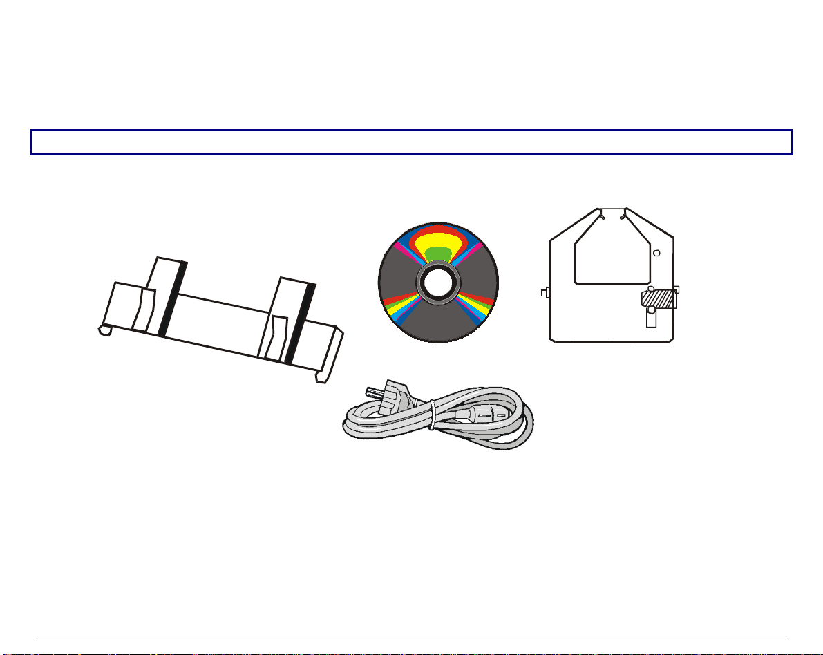
Together with the Installation Guide and the CD-ROM with the User Manual, the following
items are included in the box:
Notify any damage to your supplier.
Paper Chute
(4051/4056 plus only)
Power Cable
CD-ROM
Ribbon Cartridge
Black Ribbon - 3 Mcrt
4
P
P
r
r
i
i
n
n
t
t
e
e
r
r
P
P
a
a
r
r
t
t
s
s
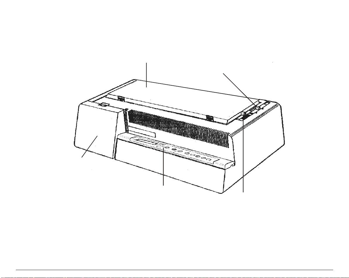
4
4
0
0
5
5
1
1
/
/
4
4
0
0
5
5
6
6
p
p
l
l
u
u
s
s
M
M
o
o
d
d
e
e
l
l
s
s
–
–
F
F
r
r
o
o
n
n
t
t
V
V
i
i
e
e
w
w
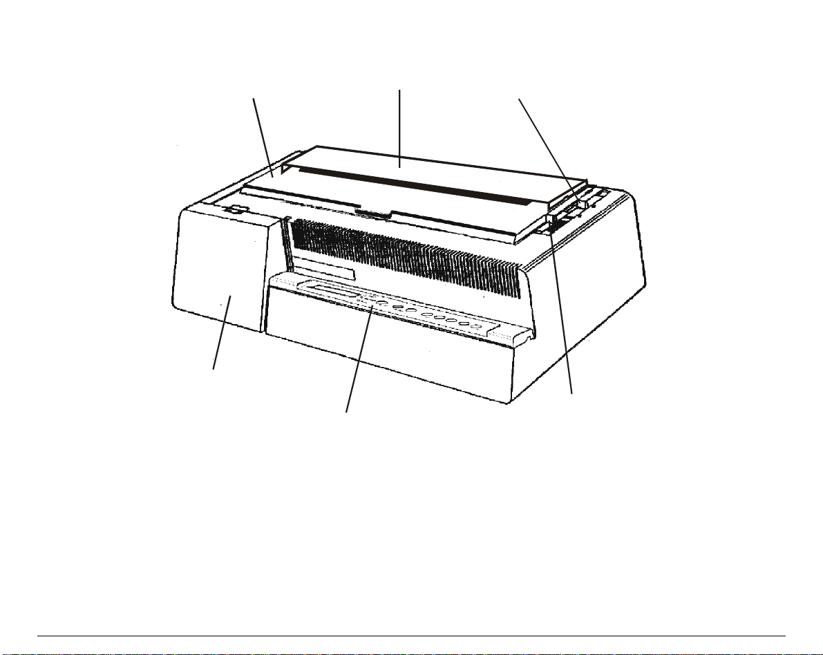
Interface B oard C ov er
Operator Panel
Pap er Thickness Le ver
Drive Se lection Lev er
Printer Cover
5
4
4
0
0
5
5
1
1
N
N
/
/
4
4
0
0
5
5
6
6
N
N
p
p
l
l
u
u
s
s
M
M
o
o
d
d
e
e
l
l
s
s
–
–
F
F
r
r
o
o
n
n
t
t
V
V
i
i
e
e
w
w
Printer Cover
Paper Chute
Drive Selection Lever
Paper Thickness Lever
Operator P anel
Interface Board Cover
6
A
A
l
l
l
l
M
M
o
o
d
d
e
e
l
l
s
s
–
–
R
R
e
e
a
a
r
r
V
V
i
i
e
e
w
w
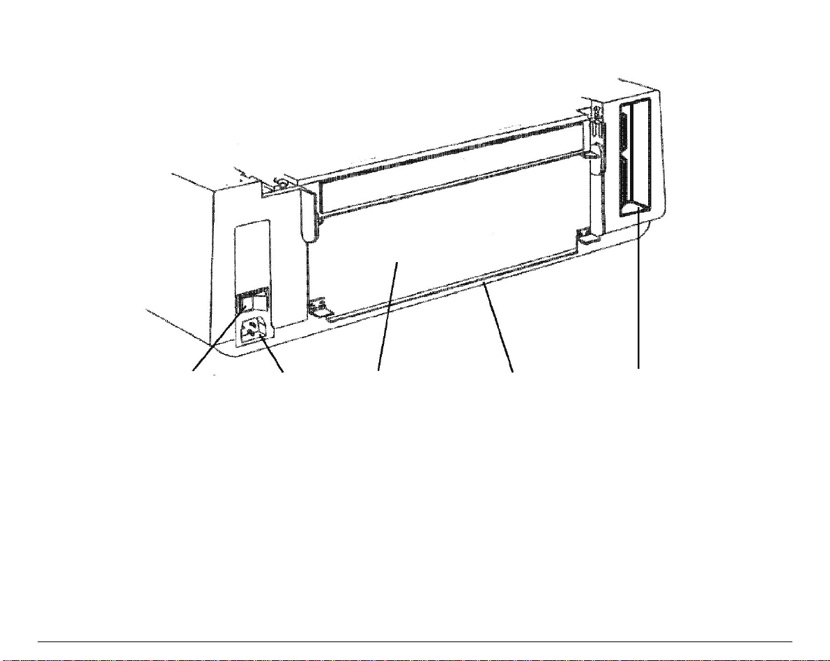
Power Switch
Tractor Cov er
Rear Paper Entry Slot
Interface Socket
Power Socket

7
S
S
e
e
t
t
t
t
i
i
n
n
g
g
U
U
p
p
Y
Y
o
o
u
u
r
r
P
P
r
r
i
i
n
n
t
t
e
e
r
r
C
C
h
h
o
o
o
o
s
s
i
i
n
n
g
g
a
a
S
S
u
u
i
i
t
t
a
a
b
b
l
l
e
e
L
L
o
o
c
c
a
a
t
t
i
i
o
o
n
n
Consider the following points when you choose the location for your printer:
• The distance between the printer and the host computer must not exceed the length of the
interface cable;
• The location must be sturdy, horizontal and stable;
• Your printer must not be exposed to direct sunli ght, extreme heat, cold, humidity or dust
see “Printer Specifications” section later;
• You need a power outlet compatible with the plug of the printer’s power cord. The voltage of
the outlet must match the voltage shown on the printer’s Rating Plate.
After selecting an installation location, install the printer making sure that there is sufficient
space for operation.
8
P
P
r
r
i
i
n
n
t
t
e
e
r
r
A
A
s
s
s
s
e
e
m
m
b
b
l
l
y
y
R
R
i
i
b
b
b
b
o
o
n
n
C
C
a
a
r
r
t
t
r
r
i
i
d
d
g
g
e
e
I
I
n
n
s
s
t
t
a
a
l
l
l
l
a
a
t
t
i
i
o
o
n
n
It is advisable to insert the ribbon cartridge while the printer is turned off.
However, your printer can be turned on during this procedure, but do not forget that it must be
disabled to print (Wait displayed and
READY
led turned off).
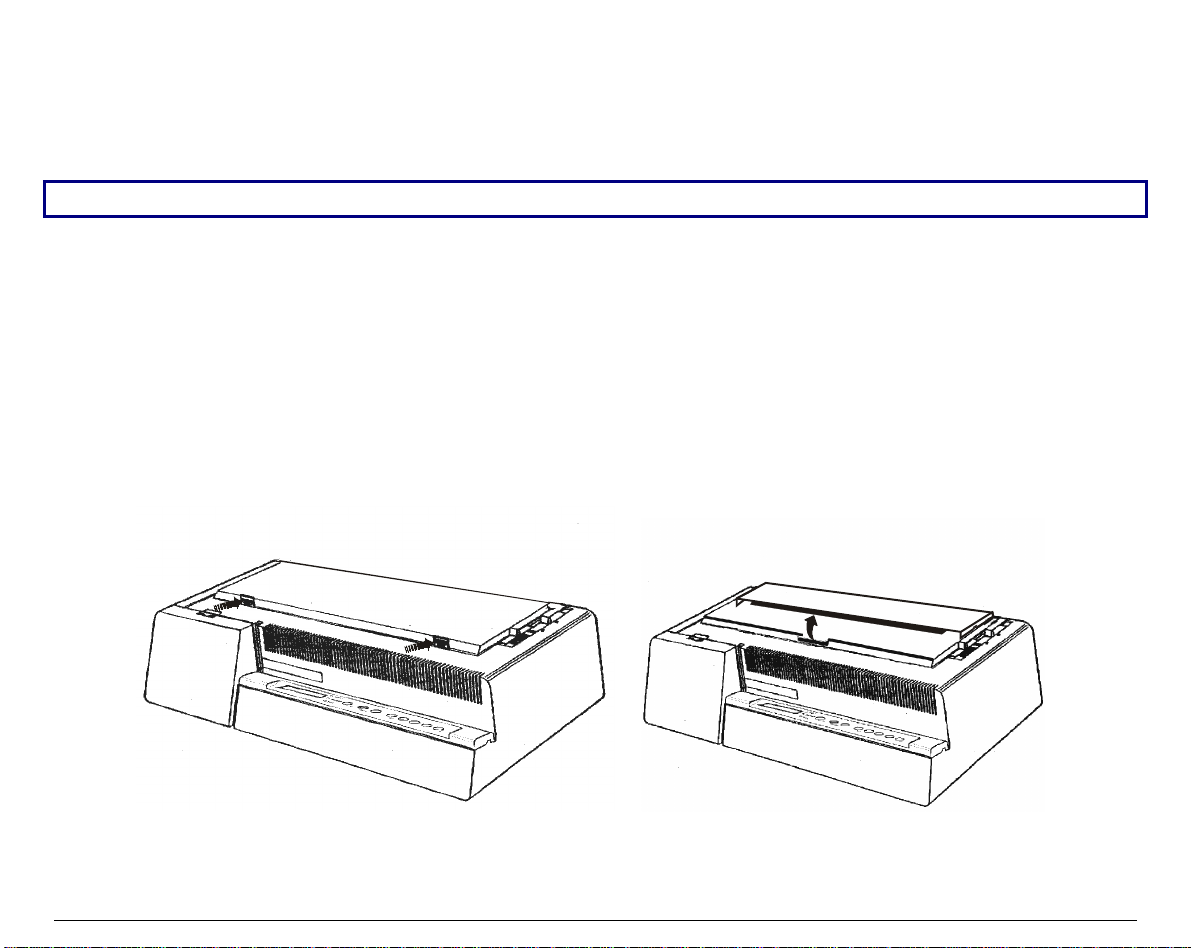
1. Remove the printer cover by pressing simultaneously the two buttons in the front part of the
cover.
• If your printer is the 4051N plus or the 4056N plus model, do not remove but lift the
printer cover.
4051/4056 plus Models 4051N/4056N plus Models
9
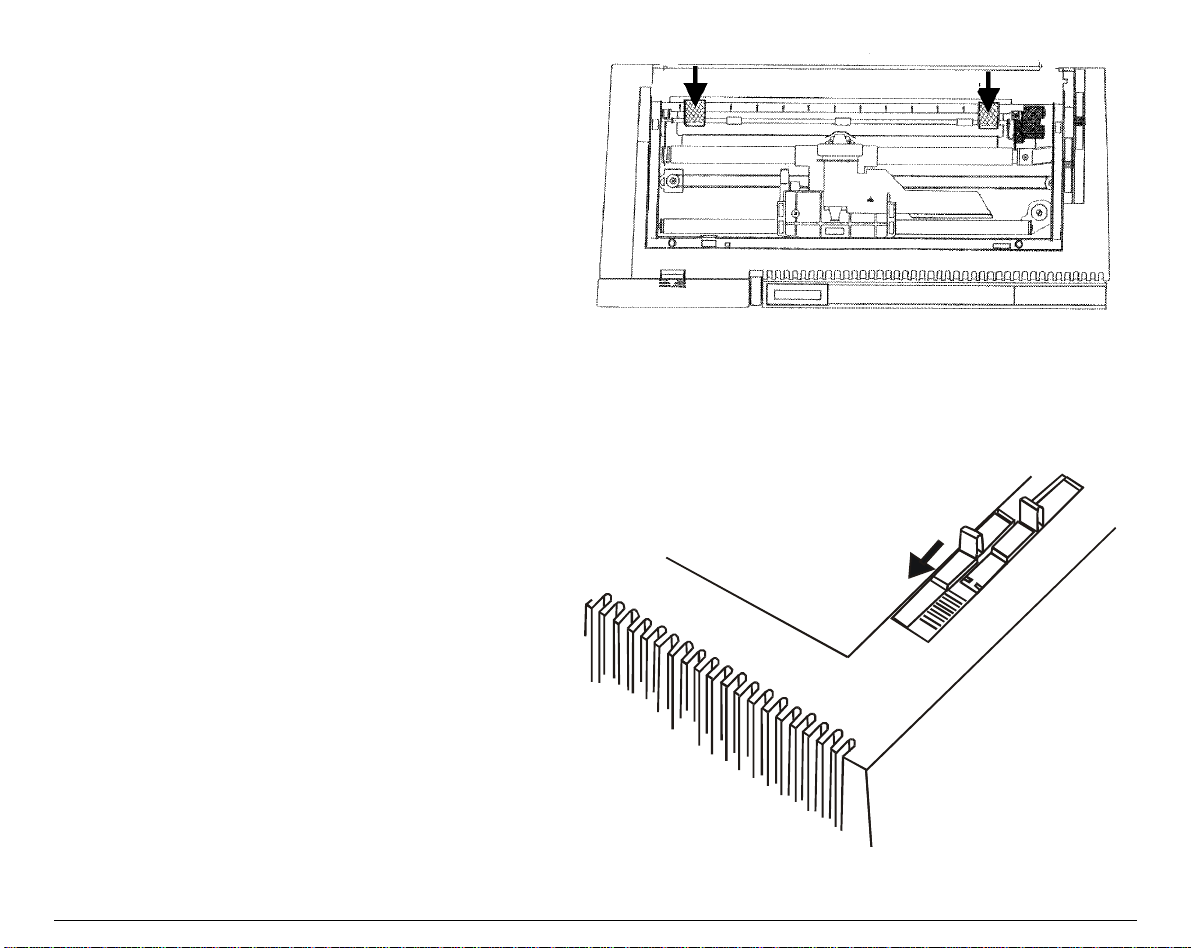
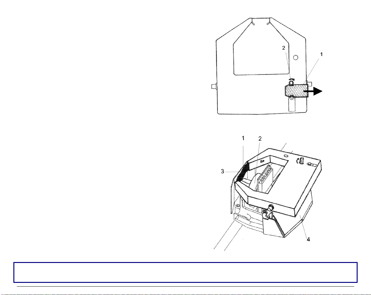
2. If you are inserting the ribbon cartridge for
the first time, do not forget to complete the
unpacking procedure by taking off the
plastic hooks that fix the paper ba il.
3. Pull the paper thickness lever tow ards the
front of the printer to facilitate ribbon
insertion.
10
4. Remove the new ribbon cartridge from its
bag. Remove and discard the holdfast (1)
that blocks the ribbon. Turn the tension
knob (2) to tighten the ribbon.
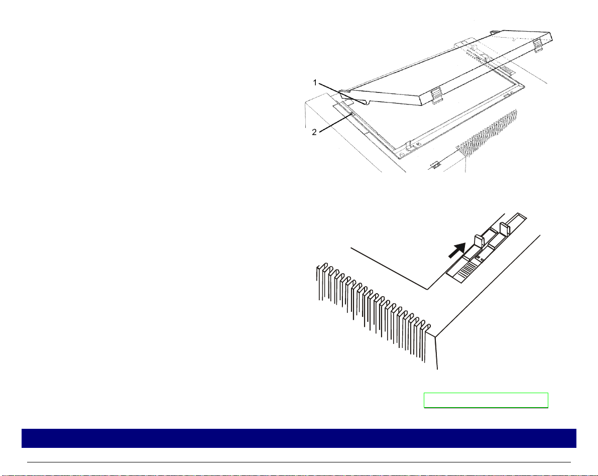
5. Insert the ribbon (1) between the print
head (2) and the print hea d mask (3). Lay
the cartridge over the printer carriage (4).
Make sure that the two pins on each side of the cartridge are positioned over t he retaining clips of
the printer carriage.
11
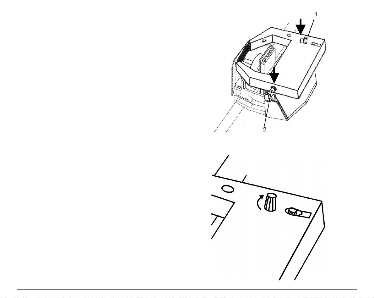
6. Push the cartridge gently down while
turning the tension knob (1). Make sure
that the cartridge clicks into place (2).
7. To tighten the ribbon, turn the tension
knob in the direction shown by the arrow
on the ribbon cartridge
12
8. Replace the pri nter cover by first inserting
the hooks (1) into the appropriate grooves
(2) and then lower the cover ensuring that
clicks in place.
• If your printer is the 4051N plus or the
4056N plus model, simply lower the
printer cover to close it.
9. Move the paper thickness lever according to the paper type:
• If a cut sheet is loaded move the lever
towards the back of the printer.
• If a multicopy-chemical paper is
loaded, first move the lever completely
towards the back of the printer, then 1
notch towards the front of the printer
for each copy.
• If a carbon multicopy-paper is loaded,
first move the lever completely
towards the back of the printer, then 2
notches towards the front of the
printer for each copy.
Now, you can load the paper and print your first test document, see “Printing the Self Test ”. If
the pattern does not satisfy your expectation, a djust the paper thickness lever again.
When printing on multicopy-paper follow the above instructions to avoid damaging the print head.
13
P
P
a
a
p
p
e
e
r
r
C
C
h
h
u
u
t
t
e
e
I
I
n
n
s
s
t
t
a
a
l
l
l
l
a
a
t
t
i
i
o
o
n
n
(
(
4
4
0
0
5
5
1
1
/
/
4
4
0
0
5
5
6
6
p
p
l
l
u
u
s
s
m
m
o
o
d
d
e
e
l
l
s
s
o
o
n
n
l
l
y
y
)
)
The paper chute is provided with the 4051plus and 4056 plus printers. To install the paper chute
in the printer follow this sequence:
To insert the paper chute correctly, make sure that you are in front of the print er and that you hold
the paper chute in the front position.
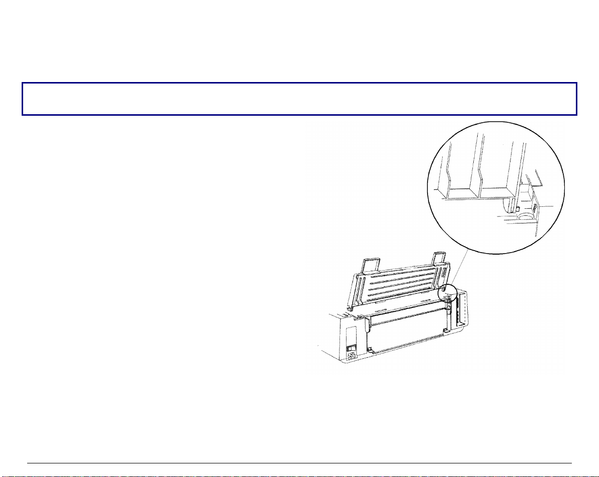
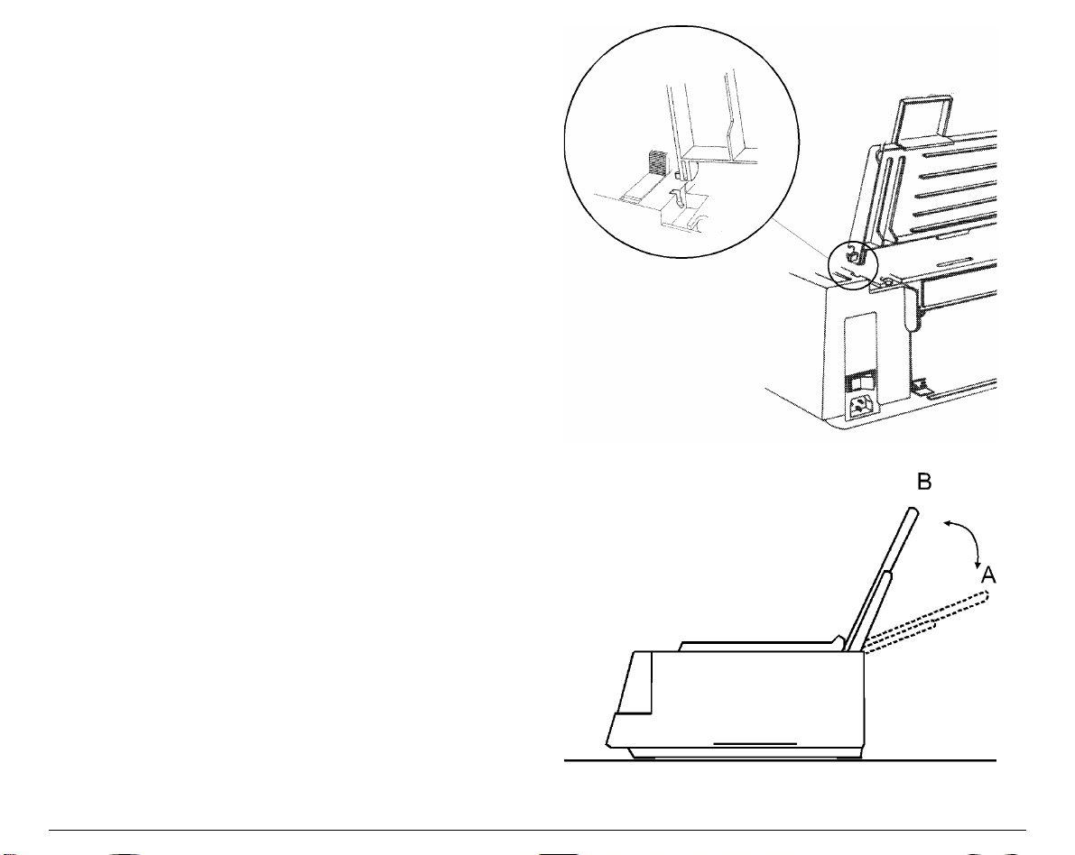
1. Insert the hook on the left side of the paper
chute in the groove situated near the paper
entry slot.
The figure shows the back of the printer and
the paper chute in the back position for a
good view of the hook and groove. For this
reason, you will see the left side of the paper
chute shown on the right.
14
2. Flex the paper chute towards the front of
the printer and insert the hook on the
opposite side of the paper chute in the
corresponding groove.
This printer accessory may assume two
different positions according to the paper
type: down position for fanfold paper (A) and
raised position for cut sheet (B).
3. If you wish to position the paper chute
down, lift it towards the back of the printer
and push it gently down until it stops. If you
wish to place the paper chute in the raised
position, lift it and hook it firmly.
15
H
H
o
o
s
s
t
t
C
C
o
o
m
m
p
p
u
u
t
t
e
e
r
r
C
C
o
o
n
n
n
n
e
e
c
c
t
t
i
i
o
o
n
n
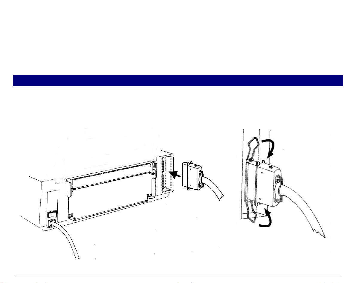
This printer can be connected to your host computer via two available interfaces. The interface
connectors are located on the rear of the printer.
• A bidirectional IEEE1284 parallel interface
• A RS-232C/422A serial interface
Make sure that both printer and host computer are switched off.
P
P
a
a
r
r
a
a
l
l
l
l
e
e
l
l
C
C
o
o
n
n
n
n
e
e
c
c
t
t
i
i
o
o
n
n
Insert the parallel interface cable into the parallel connector and fasten it by means of the clips.
16
S
S
e
e
r
r
i
i
a
a
l
l
C
C
o
o
n
n
n
n
e
e
c
c
t
t
i
i
o
o
n
n
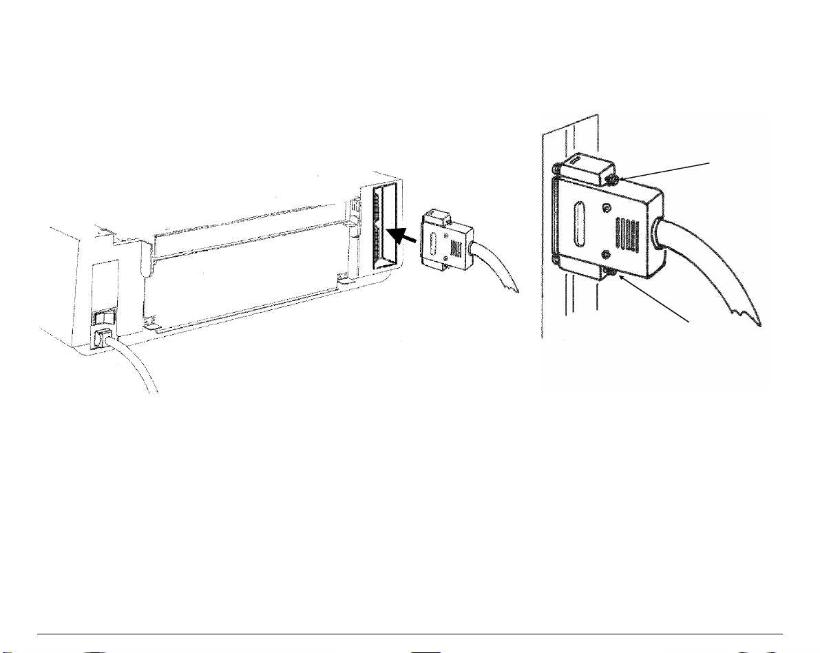
Insert the serial interface cable into the serial connector, and fasten it by means of the two
screws (use the screwdriver).

17
S
S
o
o
f
f
t
t
w
w
a
a
r
r
e
e
D
D
r
r
i
i
v
v
e
e
r
r
S
S
e
e
l
l
e
e
c
c
t
t
i
i
o
o
n
n
At this point it is necessary to configure your printer for your application package. The
installation procedures depend upon the host environment:
Follow the instructions in the readme file you find on the CD-ROM.
In a WINDOWS® 95/98/2000 environment the printer supports the Plug & Play feature.
The printer drivers of all Compuprint printers can be found at the Internet Address
http://www.compuprint.net/drivers
18
P
P
o
o
w
w
e
e
r
r
C
C
o
o
n
n
n
n
e
e
c
c
t
t
i
i
o
o
n
n
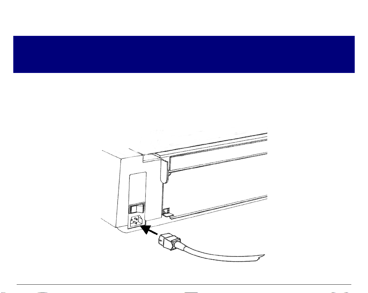
Make sure that the power outlet matches the power rating of the printer. See th e name plate of th e
printer, that you find in the rear of the printer.
Always use a grounded outlet.
Make sure that the power outlet is near the printer location and easily accessible.
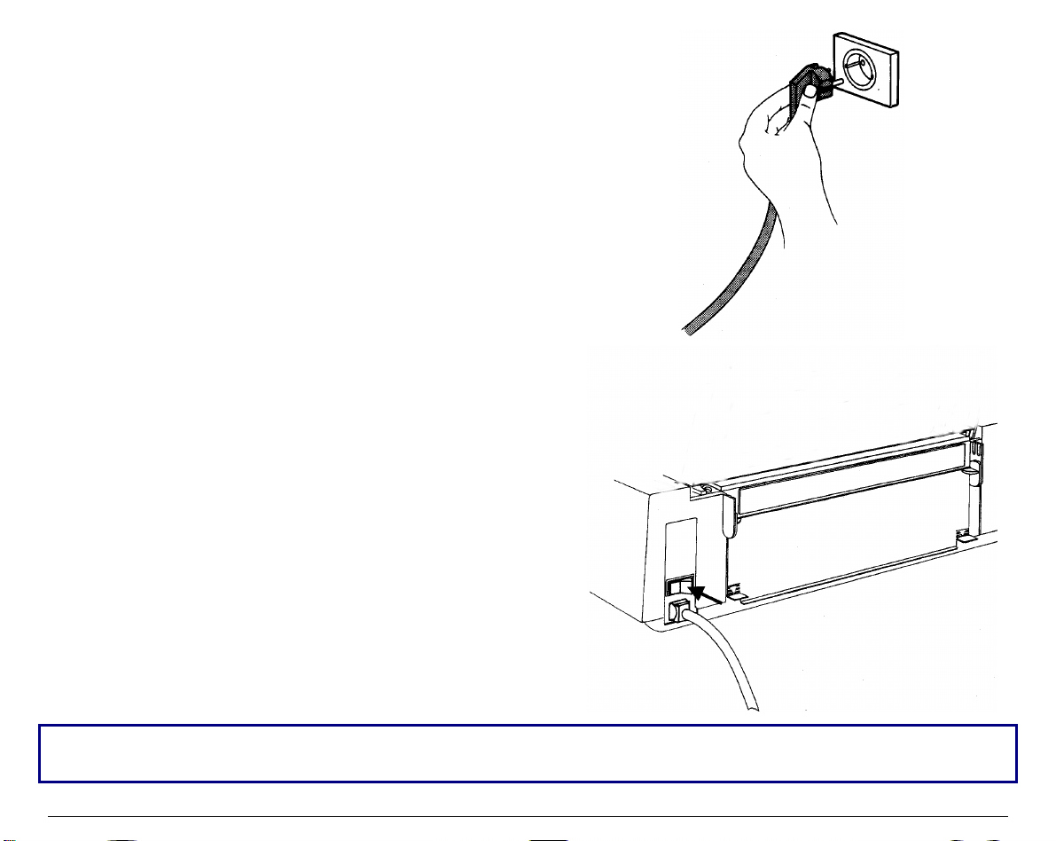
1. Make sure that the power switch at the rear of the printer is in the "printer off" position.
Insert one end of the power cable plug into the printer connector placed on the rear of the
printer.
19
2. Insert the other end of the power cable in a
convenient outlet.
3. To turn the printer on, press the part of the
power switch that now is up. The print head
moves and stops at about 6.5 inches from the left
side of the printer and the indicators on the
operator panel light up for a few seconds.
Every time the printer is turned off and you need to turn it on again, wait 3 seconds before turning
it on.
20
S
S
e
e
l
l
e
e
c
c
t
t
i
i
n
n
g
g
t
t
h
h
e
e
D
D
i
i
s
s
p
p
l
l
a
a
y
y
L
L
a
a
n
n
g
g
u
u
a
a
g
g
e
e
The display messages for this printer can be displayed in two different languages: English
(Default) and Italian.
To select the language that y ou prefer, proceed as follows:
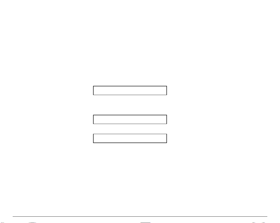
1. Enter the Power on Configuration procedure.
• Make sure that the printer is turned off.
• Keep the
PROGRAM
key pressed while you turn on the printer. After the initialization
phase the following message will be displayed:
INSTALLATION
2. Press the → key to select the function.
3. Press the ↓ key until the language first level function is displayed:
LANGUAGE
4. Press the → key to select the function. The following message will be displayed:
* English
The symbol ‘ * ’ means that the shown parameter is the selected one, in this case it is the
default value.
5. Press the → key to select it.
6. Press the
PROGRAM
key to exit the Power on Configuration procedure. From now the display
message will appear in the selected language.
21
C
C
o
o
n
n
f
f
i
i
g
g
u
u
r
r
i
i
n
n
g
g
t
t
h
h
e
e
P
P
r
r
i
i
n
n
t
t
e
e
r
r
O
O
p
p
e
e
r
r
a
a
t
t
o
o
r
r
P
P
a
a
n
n
e
e
l
l
P
P
r
r
e
e
s
s
e
e
n
n
t
t
a
a
t
t
i
i
o
o
n
n
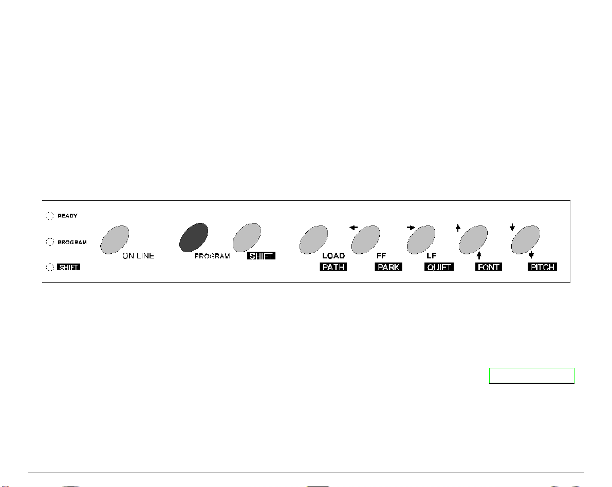
The operator panel consists of three elements:
• Display: you can see on the display various messages usually regarding the printing
functions.
• Indicators: give information about the operating state of the printer.
• Function keys: allow you to change operating state of the printer as necessary.
D
D
i
i
s
s
p
p
l
l
a
a
y
y
M
M
e
e
s
s
s
s
a
a
g
g
e
e
s
s
The display messages can be divided into three main groups:
STATUS MESSAGES
give information about the current operating printer state.
SETUP MESSAGES
are displayed during the printer setup procedure. See " Printer Setups "
later in this section.
ERROR MESSAGES
signal the printer faults.

22
Basic Indications on the Display
When turning the printer on, after the message 405x plus, the display indicates the printer
status (Ready, Wait, Busy, Quiet), the current macro (M1, M2, M3, M4) and the selected
emulation (IBM XL III or EPSON FX for the 4051/4051N plus printers and IBM XL 24E, IBM
XL24 AGM and EPSON LQ for the 4056/4056N plus printers) as follows:
Ready M1-EPS
The following list shows y o u the status and error messages in alphabe tical order:
1.Enable path SS
2.Remove paper
Displayed when Bin 1, Bin 2 (4051/4056 plus models only) or
Manual paper path loading is not successful. Check the position of the
selection lever (towards the back of the printer for sing le sheets).
1.Tear-off paper
2.Remove paper
Displayed when the fanfold paper to pa rk is too l ong. Tea r the printed
paper and press the
PARK
key again.
2. Park paper
Displayed when Park operation is not successful.
4051 plus or
4051N plus or
4056 plus or
4056N plus
This message appears on the display immediately after turning the
printer on to indicate that it is initializing to its power on setting. The
print head moves to its initial position. The printer is logically
disconnected from the host and is disabled to receive data. The
READY
indicator is turned off.
Bin 1
Displayed when ASF Bin 1 paper path is selected (4051/4056 plus
models only).
Bin 1/2
Displayed when ASF Bin 1/2 paper paths are selected (4051/4056
plus models only).
Bin 2
Displayed when ASF Bin 2 paper path is selected (4051/4056 plus
models only).

23
Buffer cleared
Displayed after input buffer clearing (all the stored data are erased).
Call Service
Displayed in rolling mode together with the failure message to
indicate a call to Service.
Carriage error
Displayed when there is an unrecoverable carriage error. This means
that the printer carriage does not move correctly. When the
Carriage error message is displayed, the i ndicator
READY
blinks.
Check that the ribbon cartridge is not used up neither damaged.
Check connection
Displayed when a DSR, DCD, or CTS signal fault occurs.
Check interface
Displayed when an Input bu ffer overflow occurs
Check its moving
Displayed when a carriage fault occurs.
Check line
Displayed when a communication error occurs.
Comm. failure
Displayed when a communication error occurs
Data lost
Displayed when an input b u ffer overflow occurs.
Enable path FF
This message appears on the display immediately after switching
Manual path to Fanfold path. Place the dri ve selection lever in the
fanfold position.
Enable path SS
This message appears on the display immediately after switching
Fanfold path to Manual path. Place the dri ve selection lever in the
single sheet position.
Fanfold
This is one of the messages that will be displayed when you press
PATH
(Shift function). Press the
SHIFT
key to select the fanfold paper
path.

24
Fanfold thru ASF
This is one of the messages that will be displayed when you press
PATH
(Shift function). Press the
SHIFT
key to select the handling of the
fanfold paper with the Automatic Sheet Feeder (option) installed
(4051/4056 plus models only).
Initializing
Displayed while the printer is turned on.
Invalid keypress
An invalid pressing of a key has occurred.
Labels
This is one of the messages that will be displayed when you press
PATH
(Shift function). Press the
SHIFT
key to select the fanfold paper with
adhesive label loading.
Load
Displayed when a paper out occurs.
Loading paper
Displayed when there is a paper loading request (fanfold or cut
sheet).
Manual
This is one of the messages that will be displayed when you press
PATH
(Shift function). Press the
SHIFT
key to select the manual cut
sheet path.
NVM changed
Displayed when NVM contents has been changed.
Parking paper
Generic status message for all parking operations.
Press any button
Generic user intervention message.
Press Park
You are requested to press the
PARK
key.
Printer failure
Displayed in case of fault during the initialization.
Printing test
Displayed while the self-test is running.
Processing
Generic wait message for an operation.
 Loading...