


 Loading...
EPSON
Serial Interface
Card
C82305*
C8230*
English
Deutsch
Français
ESpañol
Italiano
4000152
C01-00
N O T I C E
All rights reserved. Reproduction of any part of this manual in any form whatsoever
without Seiko |
Epson’s express written permission |
is forbidden. |
The contents |
of this manual are subject to change |
without notice. |
All efforts have been made to ensure the accuracy of this manual. However, should any
errorS be detected. Seiko Epson would greatly appreciate |
being informed |
of them |
The above notwithstanding. Seiko Epson can assume no |
responsibility for |
any errors |
in this manual or their consequences. |
|
|
Copyright © 1990 bySeiko Epson Corporation. Nagano, |
Japan |
|
Serial Interface |
English |
C82305 * /C82306 * |
|
Schnittstellenkarte Deutsch
C82305 * /C82306 *
Interface série |
|
|
Français |
||
C82305 * /C82306* |
||
|
Interface en serie |
|
|
Español |
||
C82305 * /C82306* |
||
|
Interfaccia seriale |
Italiano |
C82305* /C82306* |
TABLE OF CONTENTS
INTRODUCTION |
2 |
|
About |
this guide |
3 |
SETTING |
THE CONDITIONS |
4 |
Card layout |
4 |
|
DIP switch and jumper settings |
5 |
|
DIP switches |
5 |
|
Jumpers |
10 |
|
DATA ENTRY |
13 |
|
Serial communication |
13 |
|
About |
data entry |
13 |
Handshaking protocol |
14 |
|
SPECIFICATIONS |
17 |
|
HARDWARE DESCRIPTION |
19 |
|
RECOMMENDED CIRCUIT CONNECTIONS |
21 |
|
INSTALLATION |
22 |
|
INTRODUCTION
The Serial Interface Card 032305 * /C82306 * is an interface that allows asynchronous serial data communication between a host computer and an EPSON printer.
This interface card offers the following features:
• Data transmission that can be set at either RS-232D or 20 mA Current Loop levels (RS-232D has been revised from the former RS-232C. Set the signal levels for RS-232D the same as for RS-232C.)
•Handshaking protocol using X-on/X-off or DTR flag control
•Selectable data word structure that allows you to
choose parity (Odd, Even, or None) and word bit settings (either 7 or 8 bit)
• Selection of baud rate settings from 75 to 19,200 BPS (Data transmission speed is limited to 1,200 BPS when the signal level is set to 20 mA Current Loop)
l DIP switch 1 settings that you can change even after installation
About this guide
This guide is designed to give you detailed information on how to install your C82305 * /C82306 * serial interface card in a variety of EPSON printers. Installation procedures vary slightly depending upon the printer model that you have.
Also included are instructions on how to adjust the settings of the C82305 * /C82306 * interface card, as well as a general description of serial data communication.
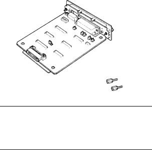
The C82305 * /C82306 * option package contains the following items:
C82305*
C82306* serial I/F card (1)
Optional connector lock nuts (2)
Note
When attaching the interface cable to the interface, you may find that the screws of your interface cable do not fit into the connector lock nuts. If this happens you will need to replace the connector lock nuts with the optional ones provided in this package.
3

SETTING THE CONDITIONS
The C82305 * /C82306 * interface card has two sets of DIP (Dual In-line Package) switches, and seven jumpers. These switches and jumpers are used for selecting various interface operations.
Card layout
The figure below shows the layout of the C82305 * /C82306 * card, and the locations of the DIP switches and jumpers.
Figure 1. Card layout
4

DIP switch and jumper settings
Before you install the C82305 * /C82306 * interface, you may need to adjust the DIP switch 2 and jumper settings. You can change the DIP switch 1 settings after you install the interface. When making DIP switch setting changes, it is best to use a pointed device, such as a ball-point pen or small screwdriver.
Caution
All changes of DIP switch and jumper settings should be made with the printer power turned off. New settings become valid only when the printer is turned on.
DIP switches
The settings on DIP switches allow you to change interface functions. The two sets of DIP switches on the C82305 * /C82306* are labelled SW1 and SW2. Each set contains a number of individual toggle-type switches
that can be set either on or off. The individual switches are referred to by set (SW1 or SW2) and number. Therefore, the switch in set SW1 marked by the small number 3 is called DIP switchl-3.
5

DIP switch 1 (interface operations)
The table below contains information on switch functions, and the factory setting of each.
Table 1. DIP switch 1
Switch |
Function |
O N |
|
OFF |
Factory |
|
number |
|
setting |
||||
|
|
|
|
|||
|
|
|
|
|
|
|
1-1 |
I/F card enable/disable |
Enable |
|
Disable |
O N |
|
(Note) |
|
|||||
|
|
I |
|
|
||
|
|
|
|
|
||
l - 2 |
Word length |
8 bit |
|
7 bit |
O N |
|
|
||||||
|
|
|
|
|
|
|
l-3 |
Parity check 1 |
|
|
|
OFF |
|
|
|
See Table 4. |
|
|||
1-4 |
Parity check 2 |
OFF |
||||
|
|
|
|
|
||
|
|
|
|
|
|
|
l-5 |
Baud rate 1 |
|
|
|
O N |
|
|
|
See Table 5. |
|
|||
l-6 |
Baud rate 2 |
OFF |
||||
|
|
|
||||
|
|
|
|
|
|
|
Note
Some printers have a selecting switch (or function) that allows you to select between the optional and original interfaces. If you install the interface card in this type of printer, you should set DIP switch l-l on the interface card to ON and also change the setting in the printer to select the optional interface.
6
Loading...