


SHERWOODINDUSTRIESISANENVIRONMENTALLYRESPONSIBLECOMPANY.THISMANUALISPRINTEDONRECYCLEDPAPER.
PLEASE KEEP THESE INSTRUCTIONS FOR FUTURE REFERENCE
EG28 DV
BY: SHERWOOD
  INDUSTRIES LTD
OWNER’S MANUAL
WHAT TO DO IF YOU SMELL GAS
• Open windows/Extinguish any open flame.
• Do not try to light any appliance.
• Do not touch any electrical switch or use any phone in your building.
• Immediately call your gas supplier from a neighbour’s phone. Follow the gas supplier’s instructions.
• If you cannot reach your gas supplier, call the fire department.
This appliance may be installed in an after market permanently located, manufactured (mobile) home, where not prohibited by local codes.
This appliance is only for use with the type of gas indicated on the rating plate. This appliance is not convertible for use with other gases, unless a certified kit is used.
WARNING
If the information in this manual is not followed exactly, a fire or explosion may result causing property damage, personal injury or loss of life. Installation and service must be performed by a qualified installer, service agency or the gas supplier.
FOR YOUR SAFETY: Do not store or use gasoline or other Flammable vapours and liquids in the vicinity of this or any other appliance.
Massachusetts installations (Warning): This product must be installed by a licensed plumber or gas fitter when installed within the Commonwealth of Massachusetts. Other Massachusetts code requirements: Flexible connector must not be longer than 36in., a shut off valve must be installed; only direct vent sealed combustion products are approved for bedrooms/bathrooms. A carbon monoxide detector is required in all rooms containing gas fired direct vent appliances.
EG28-120
Safety Precautions
FORSAFEINSTALLATIONANDOPERATIONOFYOUR“ENVIRO”HEATER, PLEASE CAREFULLY READ THE FOLLOWING INFORMATION:
•All ENVIRO gas-fired appliances must be installed in accordance with their instructions. Carefully read all the instructions in this manual first. Consult the building authority having jurisdiction to determine the need for a permit prior to commencing the installation.
•NOTE: Failure to follow these instructions could cause a malfunction of the fireplace, which could result in death, serious bodily injury, and/or property damage.
•Failure to follow these instructions may also void your fire insurance and/or warranty.
GENERAL
•Installation and repair should be done by a
qualified service person. The appliance should be inspected before the first use and, annually thereafter by a qualified service person. More frequent cleaning may be required due to excessive lint from carpeting, bedding material, etc. It is imperative the control compartments, burners and circulating air passageways of the appliance be kept clean.
• Due to high temperatures, the appliance should be located out of high traffic areas and away from furniture and draperies.
Children and adults should be alerted to the hazards of high surface temperatures and should stay away to avoid burns or clothing ignition.
Young children should be carefully supervised when they are in the same room as the appliance.
FOR YOUR SAFETY
•Installation and service must be performed by a qualified installer, service agency or gas supplier.
•This installation must conform to local codes or, in the absence of local codes, to the current CAN/CGAB149 installation code (Canada) or National Fuel Gas Code ANSI Z223.1.2 (USA).
•To prevent injury, do not allow anyone who is unfamiliar with the stove to operate it.
•To prevent injury, if the pilot or pilot and burners have gone out on their own, open the glass door and wait 5 minutes to air out before attempting to re-light the stove.
•Always keep the area around this appliance clear of combustible material, gasoline and other flammable liquids and vapours.
•This appliance should not be used as a drying rack for clothing or for hanging Christmas stockings/ decorations.
•Due to the paint curing on the stove, a faint odor and slight smoking will likely be noticed when the stove is first used. Open a window until the smoking stops.
Always connect this gas stove to a vent system and vent to the outside of the building envelope. Never vent to another room or inside the building. Make sure the specified vent pipe is used; properly sized and of adequate height to provide sufficient draft. Inspect the venting system annually for blockage and signs of deterioration.
WARNING: Failure to position the parts in accordance with the diagrams in this booklet, or failure to use only parts specifically approved with this appliance may result in property damage or personal injury.
WARNING: Do not operate with the glass front removed, cracked or broken. Replacement of the glass must be done by a licensed or qualified service person.
•Never use solid fuels such as wood, paper, cardboard, coal, or any flammable liquids, etc., in this appliance.
•Do not use this heater if any part has been under water. Immediately call a qualified service technician to inspect the heater and to replace any part of the control or gas control systems that have been under water.
•Do not abuse the glass by striking it or slamming the door shut.
2

Table of Contents
Safety Precautions............................................................................... |
2 |
Table of Contents................................................................................. |
3 |
Codes And Approvals........................................................................... |
4 |
Specifications...................................................................................... |
5 |
Dimensions.............................................................................. |
5 |
Rating Label Location................................................................ |
5 |
Operating Instructions......................................................................... |
6 |
Lighting Instructions................................................................. |
6 |
Normal Sounds During Operation............................................... |
7 |
Adjusting The Venturies............................................................. |
7 |
Maintenance and Service...................................................................... |
8 |
Opening The Door.................................................................... |
8 |
Cleaning The Glass................................................................... |
8 |
To Replace Door........................................................................ |
8 |
Cleaning The Firebox................................................................ |
8 |
Cleaning Plated Surfaces........................................................... |
9 |
Burner Removal........................................................................ |
9 |
Replacing The Blower................................................................ |
9 |
Fuel Conversion...................................................................... |
10 |
Initial Installation............................................................................... |
12 |
Preparation For Installation...................................................... |
12 |
Clearances to Combustibles..................................................... |
12 |
Planning Your Installation........................................................ |
13 |
Corner Installations................................................................. |
14 |
Mobile Home Installation......................................................... |
14 |
Vent Termination Restrictions................................................... |
15 |
Freestanding Direct Vent Kit With Coupler................................. |
16 |
Other Approved Vent Parts...................................................... |
18 |
Vent Configurations................................................................. |
20 |
Vent Restrictor Ring................................................................ |
20 |
Horizontal Installation.............................................................. |
21 |
Vertical Installation.................................................................. |
23 |
Cathedral Ceiling Installation.................................................... |
25 |
Venting into a Class ‘A’ Chimney............................................... |
26 |
Electrical Requirements........................................................... |
27 |
Gas Line Connection and Testing.............................................. |
28 |
Secondary Installation........................................................................ |
29 |
Log Set and Embers Installation............................................... |
29 |
Trouble Shooting................................................................................ |
31 |
Parts List........................................................................................... |
32 |
Parts Diagram - Chassis...................................................................... |
34 |
Parts Diagram - Gas Tray & Door......................................................... |
35 |
Warranty........................................................................................... |
36 |
Installation Data Sheet....................................................................... |
39 |
3
Codes And Approvals
DIRECT VENT: This type is identified by the suffix DV. This appliance draws all of its air for combustion from outside the dwelling, through a specially designed vent pipe system.
This appliance has been tested and approved for installations from 0 feet to 4500 feet (1372 m) above sea level.
In the USA: The appliance may be installed at higher altitudes. Please refer to your American Gas Association guidelines which state: the sea level rated input of Gas Designed Appliances installed at elevations above 2000 feet (610 m) is to be reduced 4% for each 1000 feet (305 m) above sea level. Refer also to local authorities or codes which have jurisdiction in your area regarding the de-rate guidelines.
In Canada: When the appliance is installed at elevations above 4500 feet (1372 m), the certified high altitude rating shall be reduced at the rate of 4% for each additional 1000 feet (305 m).
• This appliance has been tested by INTERTEK (Warnock Hersey) and found to comply with the established VENTED GAS FIREPLACE HEATER standards in CANADA and the USA as follows:
VENTED GAS FIREPLACE HEATER (EG28 DV NG/LPG)
TESTED TO: ANSI Z21.88a-2003/CSA 2.33a-2003 VENTED GAS FIREPLACE HEATERS
CAN/CGA 2.17-M91 GAS FIRED APPLIANCES FOR HIGH ALTITUDES
CSA P.4.1-02 TESTING METHOD FOR MEASURING ANNUAL FIREPLACE EFFICIENCY
This ENVIRO EG28 DV Fireplace:
•Has been certified for use with either natural or propane gases. (See rating label.)
•Is not for use with solid fuels.
•Is approved for bedroom or bed sitting room. (IN CANADA: must be installed with a listed wall thermostat. IN
USA: see current ANSI Z223.1 for installation instructions.)
•Must be installed in accordance with local codes. If none exist, use current installation code CAN/CGA B149 in Canada or ANSI Z223.1/NFPA 54 in the USA.
•Must be properly connected to an approved venting system and not connected to a chimney flue serving a separate solid-fuel burning appliance.
• Manufactured (mobile) home installation must be in accordance with the Manufactured Home Construction and Safety Standard, UL 307B, Title 24 CFR, Part 3280 and/or The Standard for Manufactured Home Installations, ANSI A225.1/NFPA 501A. The unit must be bolted to the floor of the mobile home and must be electrically grounded to the steel chassis.
•Are approved for installation on combustible materials (i.e. Wood, carpet or linoleum).
•Is not approved for closet or recessed installations.
IMPORTANT NOTICE (Regarding first fire up): When the unit is turned on for the first time, it should be turned onto high without the fan on for the first 4 hours. This will cure the paint, logs, gasket material and other products used in the manufacturing process. It is advisable to open a window or door, as the unit will start to smoke and can irritate some people. After the unit has gone through the first burn turn the unit off including the pilot, let the unit get cold then remove the glass door and clean it with a good gas fireplace glass cleaner, available at your local ENVIRO dealer.
4
Specifications
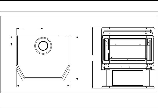
DIMENSIONS:
Shipping Weight 210 lbs (95 kg) |
|
11" |
|
(279 mm) |
|
(1024"mm) |
|
19" |
27 1/2" |
(483 mm) |
(699 mm) |
22" (559 mm)
Figure 1: EG28 Exterior Dimensions.
RATING LABEL LOCATION:
The rating label is found inside the right cabinet side panel.
5
Operating Instructions
FOR YOUR SAFETY READ COMPLETELY BEFORE OPERATING.
LIGHTING INSTRUCTIONS: |
|
|
|
||
|
|
|
|
|
CAUTION:Hot while operating. |
|
|
|
|
|
Do not touch, severe burns may result. |
|
|
OUT |
|
IN |
Keep children, clothing, furniture, |
TP |
|
|
gasoline or other flammable vapors |
||
|
|
|
|
||
TP TH |
IH |
L |
O |
|
away. |
|
|
O |
|
FF |
|
|
|
|
|
CAUTION: Do not operate this fireplace with the |
|
|
|
|
|
TO |
|
|
|
|
|
P |
|
TH |
|
|
|
I |
|
|
|
|
L |
glass removed, cracked or broken. Replacement |
|
|
|
|
NO |
||
|
|
|
|
||
|
TOLI |
|
|
|
of the panel(s) should be done by a licensed or |
|
P |
|
|
|
|
|
|
|
|
|
qualified person! This appliance needs fresh air |
|
|
|
|
|
for safe operation and must be installed with |
|
|
|
|
|
provisions for combustion and ventilation air. See |
|
|
|
|
|
installation and operating instructions manual. |
|
|
|
|
|
Keep burner and control compartment clean. |
WARNING: Improper installation, adjustment, alteration, service or maintenance can cause injury or property damage, or loss of life. Refer to owner's information manual provided with this appliance. For assistance or additional information consult a qualified installer, service agency or the gas supplier. See installation and operating instructions accompanying appliance. Installation and service must be performed by a qualified installer, service agency, or the gas supplier
 FOR YOUR SAFETY READ BEFORE OPERATING

WARNING: IF YOU DO NOT FOLLOW THESE INSTRUCTIONS EXACTLY, A FIRE OR EXPLOSION MAY RESULT CAUSING
PROPERTY DAMAGE, PERSONAL INJURY OR LOSS OF LIFE.
A)This appliance is equipped with a pilot, which must be lit by hand by following these instructions exactly.
B)BEFORE LIGHTING smell all around the appliance area
for gas and next to the floor because some gas is heavier than air and will settle on the floor.
WHAT TO DO IF YOU SMELL GAS:
Do not try to light any appliance. Do not touch any electrical switch: do not use any phone in your building. Immediately call your gas supplier from a neighbor's phone. Follow the gas suppliers instructions. If you cannot reach your gas supplier, call the fire department.
C)Use only your hand to push in or turn the gas control knob; NEVER use tools. If the knob will not push in or turn by hand, do not try to repair it. Call a qualified service technician. Force or attempted repair may result in a fire or explosion.
D)Do not use this appliance if any part has been under water.
Immediately call a qualified service technician to inspect the appliance and to replace any part of the control system and any gas control which has been under water.
 LIGHTING INSTRUCTIONS

1.STOP! Read the safety information above on this label.
2.Turn off all electrical power to this appliance.
3.Turn off the gas control knob clockwise to the off position.
4.Open door. Wait fIve (5) minutes to clear out any gas. Close door. If you smell gas STOP! Follow “B” in the above safety information. If you do not smell gas go to the next step.
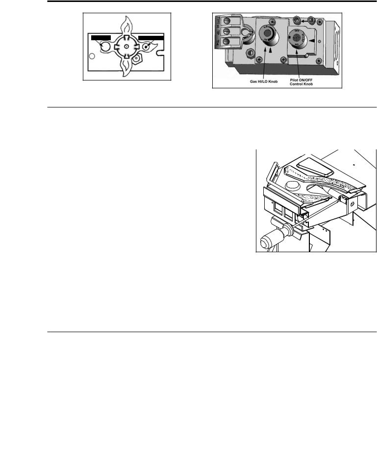
5.Find pilot-located to the right between the front and rear
burner. Turn the gas control knob counter-clockwise to “PILOT”. Push the gas control in fully and hold, keep knob depressed for about 30 seconds after the pilot is lit. Release knob. If pilot goes out, repeat steps 4 through 5.
WARNING: this gas valve has a lockout device, which will not allow the pilot burner to be relit until the thermocouple has cooled. If the knob does does not pop up when released, stop and immediately call your service technician or gas supplier. If the pilot does not stay lit after several tries, turn the gas control knob to “OFF” and call your service technician or gas supplier.
6.Turn the gas control knob counter clockwise  to the “ON” position. Flip the burner switch to “ON” THEN TURN THE “HI/LOW” knob to the desired setting.
7.Turn on the electrical power to the unit.
 TO TURN OFF GAS TO APPLIANCE

1. Flip burner switch to “OFF” |
|
3. Turn off all electrical power to the appliance if service is to |
2. Turn the gas control knob clockwise |
to the “OFF” position. |
be performed. |
Figure 2: Lighting Instructions.
6
Operating Instructions
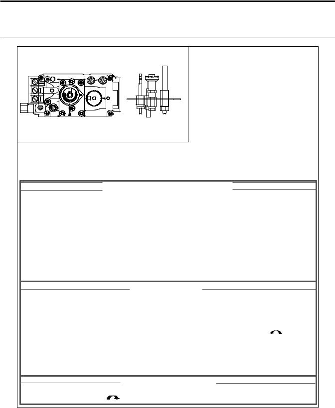
Figure 3: Pilot Burning.
Figure 4: Gas Valve.
ADJUSTING THE VENTURIES:
•Remove the ash shelf by undoing the screw at each end, pull shelf towards you.
•Remove one screw from the cover plate located below the ash shelf. Loosen the other screw (do not remove) swing the cover plate out of the way and tighten screw down to hold it in place.
•With along screwdriver rotate spring clips to open or close the shutter to the desired setting.
The venturies allows the amount of air coming into the fireplace 
to be adjusted in order to accommodate different climates and venting arrangements. Start the pilot and then the burner. Make
sure the pilot flame is burning normally and none of the burner ports are plugged. Let the fireplace burn for roughly fifteen minutes and then examine the flames, compare the flames to Figure 46.
The ideal flame will be blue at the base and light orange above. The flames should be of medium height. If the flames look like this, no venturi adjustment is needed. If the flames are fairly short and mostly blue, the fireplace is getting too much air. Therefore, the venturies should be closed slightly until the correct flames are achieved. Flames that are very orange, with tall, dark, stringy
Figure 5: Venturi Adjustment.
tips, are not getting enough air. Open the venturi until the flames clean up. If the venturi is opened, or closed all the way, and the correct flames cannot be attained, turn off the gas and contact the dealer.
Warning: Incorrect venturi adjustment may lead to improper combustion, which is a safety hazard. Contact the dealer if there is any concern about the venturi adjustment.
Table 1: Venturi Setting
|
NG |
LP |
|
|
|
Venturi Setting |
1/16” min. |
1⁄4” min. |
NORMAL SOUNDS DURING OPERATION:
|
Table 2: Normal Sounds |
|
|
Component |
Sound & Reason |
|
|
EG28 |
Creaking when heating up or cooling down. |
|
|
Burner |
Light pop or poof when turned off; this is more common with LP units. |
|
|
Temperature Sensor |
Clinking when it senses to turn the blower on or off. |
|
|
Pilot Flame |
Quiet whisper while the pilot flame in on. |
|
|
Blower / Fan |
Air movement that increase and decreases with the speed of the blower. The |
|
blower is pushing the heat from the fireplace into the room. |
|
|
Gas Control Valve |
Dull click when turning on or off, this is the valve opening and closing. |
|
|
7
Maintenance and Service
Periodically check to ensure that your direct vent system is clean.
Periodically check the pilot and burner. Check to see that all the burner ports are clean and clear. Check the pilot head for blockage. Check to ensure the pilot flame is blue with no or very small yellow tips.
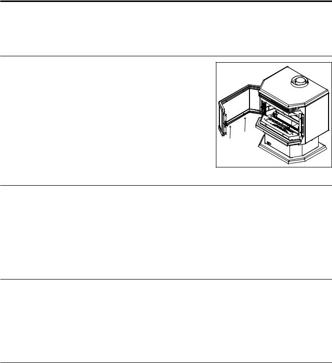
OPENING THE DOOR:
Turn unit off and wait until the appliance has cooled down.
1.Open the right hand hinged side flap, which will expose a door fastener. Using a 1⁄2” wrench, loosen the fastener.
2.Due to the shape of the bay window door. You must also open the left-hand side flap before attempting to open the door.
3.If the door must be removed open the door and lift the door pins out of the hinges (see figure 6).
4.Ensure the door is properly fastened after cleaning before attempting to re-light the appliance.
CLEANING THE GLASS:
|
|
Figure 6: Removing the Door.
Allow the glass to cool before cleaning. It will be necessary to clean the ceramic glass periodically. During a cold start up, condensation will sometimes form on the glass. This is a normal condition with all gas fireplaces and stoves. However, this condensation can allow dust and lint to cling to the glass surface. Initial paint curing of the appliance can leave behind a slight film on the glass. This is a temporary problem. It is therefore recommended that the glass be cleaned initially after about the first four hour of use. Depending upon the amount of use, cleaning should be required no more than two or three times per season. To clean the door, use a mild glass cleaner and a soft cloth or a glass cleaner available from your Enviro dealer. Abrasive cleaners will damage the glass.
TO REPLACE DOOR:
The glass in this appliance is an integral part of the door assembly. If the glass is damaged or broken a replacement inner door with glass assembly must be purchased.
The glass in this appliance is ceramic. If the glass is damaged or broken a factory door with glass replacement must be used.
Remove the door with glass, a new door assembly must be purchased from an ENVIRO dealer (part #: EG28-103). Do not use a substitute materials; it will void the warranty.
CLEANING THE INSIDE OF THE FIREBOX:
1.Turn off the unit and allow it to cool down completely.
2.Remove the logs carefully from the firebox. Gently remove the embers and place on a piece of paper towel, until ready to replace.
3.Vacuum the bottom of the firebox thoroughly. Carefully clean off any dust on the logs and remove any lint from the main burner and pilot burner.
4.After carefully replacing the log and embers in their correct positions (see SECONDARY INSTALLATION - INSTALLATION OF LOG SET AND EMBERS), and the door has been resealed, re-light the pilot, following the instructions on the lighting label attached to the unit.
8
Maintenance and Service
CLEANING PLATED SURFACES:
It is important to note that fingerprints and other marks can leave a permanent stain on plated finishes. To avoid this, give the face a quick wipe with denatured alcohol on a soft cloth BEFORE lighting the fireplace. Never clean the face when it is not cool. Do not use other cleaners as they may leave a residue, which can become permanently etched into the surface.
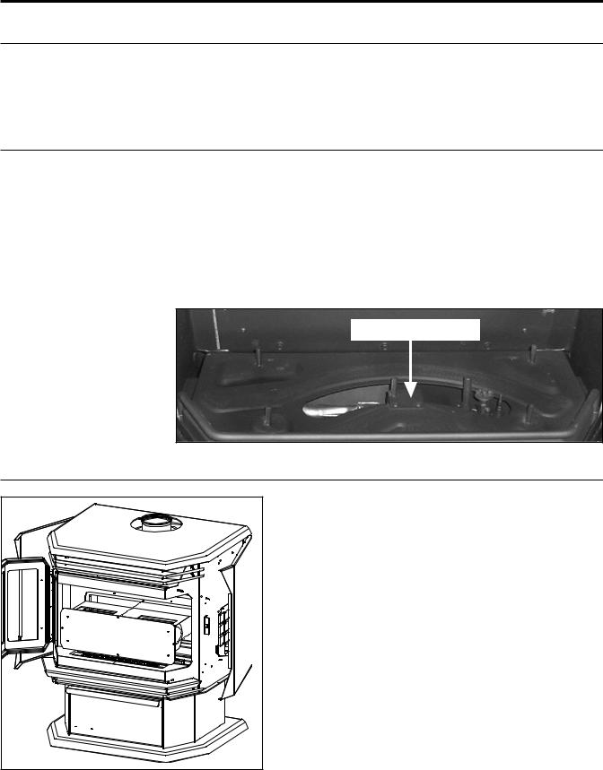
BLOWER REMOVAL:
The burner may need to be removed for a few reasons, including cleaning under the burner, converting the unit to a different gas type, or to replace the burner altogether. Proceed only when the unit has completely cooled down.
1.Remove the door as shown in the MAINTENANCE AND SERVICE - OPENING THE DOOR.
2.Remove the two (2) T-20 screws that fasten the lower half of the burner bracket to the burner tray, located inside the large hole in the burner (see Figure 7). Do not remove the screws that fasten the upper half of the burner bracket to the burner.
3.Slide the burner to the left then lift the burner assembly up then out.
To re-install the burner follow steps 1-3 in reverse. When placing the burner back in the unit ensure that the venturi box under the burner is lined up.
|
Figure 7: Blower (Fan) Removal. |
|
BLOWER REMOVAL: |
|
|
1. |
Turn the unit off, allow it to cool down completely, |
|
|
and remove the door as shown in the MAINTENANCE AND |
|
|
SERVICE - OPENING THE DOOR.. |
|
2. Remove the log set carefully. |
|
|
3. |
Remove the burner tray assembly, see MAINTENANCE AND |
|
|
SERVICE - BURNER REMOVAL. |
|
4. |
Remove the four (4) 5/16” bolts that hold the blower |
|
|
mounting plate to the back firewall. Use a light |
|
|
lubricating oil on screws before removal. |
|
5. |
Carefully pull the blower assembly into the firebox |
|
|
(see Figure 8) disconnect the blower leads from the |
|
|
harness and remove blower. |
|
6. |
To re-install, check mounting plate gasket if damaged |
|
|
replace with new one and reverse steps 1 through 4. |
|
|
Refer to “SECONDARY INSTALLATION - |
LOG SET AND EMBERS |
Figure 8: Blower (Fan) Removal. |
INSTALLATION”. |
|
|
|
|
9
Maintenance And Service
FUEL CONVERSION:
TO BE INSTALLED BY A QUALIFIED SERVICE AGENCY ONLY
Please read and understand these instructions before installing.
Warning: Thisconversionkitshallbeinstalledbyaqualifiedserviceagencyinaccordance with the manufacturer’s instructions and all applicable codes and requirements of the authority having jurisdiction. If the information in these instructions is not followed exactly, a fire, explosion or production of carbon monoxide may result causing property damage, personal injury or loss of life. The qualified service agency is responsible for the proper installation of this kit. The installation is not proper or complete until the operation of the converted appliance is checked as specified in the manufacturer’s instructions supplied with the kit.
Kit Parts List:
1 - Orifice (NG - #43 DMS or LP - #53 DMS) 1 - Pilot Injector (NG 0.62 mm; LP 0.35 mm) 1 - Installation instruction sheet
1 - Conversion label
Carefully inspect all parts supplied with this conversion kit. If any parts have been damaged or are missing, contact your dealer, distributor or courier company to have them replaced before starting this installation.
Conversion Kit Installation:
1.Turn control knob on the gas valve to the “OFF” position and shut the gas supply off at the shut-off valve upstream of the unit. CAUTION: The gas supply must be shut off prior to disconnecting the electrical power and before proceeding with the conversion. Allow the valve and unit to cool down to room temperature.
2.Remove the glass as shown in the MAINTENANCE AND SERVICE - OPENING THE DOOR.
3.Carefully remove the log set and ember material if they are installed.
4.Remove the burner as shown in the MAINTENANCE AND SERVICE - BURNER REMOVAL.
5.Convert the burner orifice(s):
a)Remove the main burner orifice with a 1⁄2 inch deep socket.
b)Put a bead of pipe-thread sealant or approved Teflon tape on the orifice threads before installing into the brass elbow.
c)Install the new orifice(s) from the kit into the brass elbow.
6.Convert the pilot injector:
a)Pull the pilot hood straight up to access the pilot injector.
b)Using a 5/32” or 4 mm Allen key, remove the pilot injector.
c)Install the new pilot injector supplied with this conversion kit. Simply screw the new injector inside the pilot hood using the Allen key,
d)Reinstall the hood by placing the hood on the assembly, line up the key
way, and snap into place.
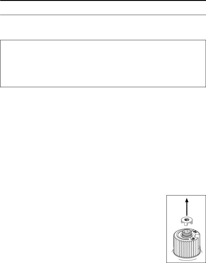
Figure 9: Removing
valve cap.
10
Maintenance And Service
7.Convert the SIT gas valve:
a)Remove the black protection cap from the HI/LO knob by hand shown in Figure 9.
b)Insert a 5/32” or 4 mm Allen wrench into the hexagonal key-way of the screw (see Figure 10), rotate it counter-clockwise until it is free and extract it.
c)Check that the screw is clean and if necessary remove dirt.
d)Flip the screw (refer to Figure 11).
e)Using the Allen wrench as shown in Figure 10, rotate the screw clockwise until a torque of 9 inch lbs. WARNING! Do not over tighten the screw. It is recommended that you grip the wrench by the short side.
f)Verify that if the conversion is from NG to LPG, the screw must be re-assembled with the red o- ring visible (refer to Figure 12). If the conversion is from LPG to NG, the red o-ring of the screw
|
must be not visible. |
Figure 11: Flip valve |
|
Figure 10: Removing valve |
screw. |
||
screw. |
|
|
|
|
|
||
g)Re-attach the black protection cap that was removed in step a (Figure 9).
8.Reinstall the burner, brick panels, log set, embers, and glass door.
Also refer to SECONDARY INSTALLATION - INSTALLING LOG SET AND EMBERS. When
re-installing the burner, ensure that the pilot hood in in line with the
small hole at the edge of front and rear burner. On some units you will need to pay special attention when installing the burner that the venturi adjustment rod is properly installed into the venturi adjustment piece welded to the burner venturi tube
9.Reconnect the main gas line if it was disconnected and open the shut-off valve at the gas line to the unit.
10.Use a small brush to apply a warm soapy water solution to all gas connections (use a half dish soap and half warm water). If a gas leak is present, bubbling will occur. Gas leaks can be repaired by using an approved pipe thread sealant or approved Teflon tape. NEVER USE AN OPEN FLAME WHEN TESTING FOR LEAKS.
11.Reconnect the electrical power to the unit.
12.Relight the main burner in both the “HI” and “LO” positions to verify proper burner ignition and operation and proper flame appearance. Also refer to SECONDARY INSTALLATION - LOG SET AND EMBERS INSTALLATION for a flame appearance picture.
13.MAKE SURE that the conversion label is installed on or close to the rating label to signify that the unit has been converted to a different fuel type.
11
Initial Installation
QUALIFIED INSTALLERS ONLY
WARNING:
Operation of this heater when not connected to a properly installed and maintained venting system can result in carbon monoxide (CO) poisoning and possible death.
PREPARATION FOR INSTALLATION:
•Remove the packaging from the appliance, and check to make sure there is no damage. If damage is found, please report it to both the carrier and your dealer as soon as possible.
•Before beginning, carefully check the glass door and the log set
•Locate a position where the flue system of the stove can be properly installed without damaging the integrity of the building; e.g. cutting a wall or ceiling joist.
•Check stove and flue system clearance requirements.
•Locate the stove where it can be accessed by a gas supply line.
•Locate the stove in a large and open room that is centrally located in the house. This will optimize heat circulation and comfort.
•As the stove is equipped with a convection fan, ensure that an electrical outlet is within 6 ft (1.8 m) of the stove.
•The flow of combustion and ventilation air must not be obstructed.
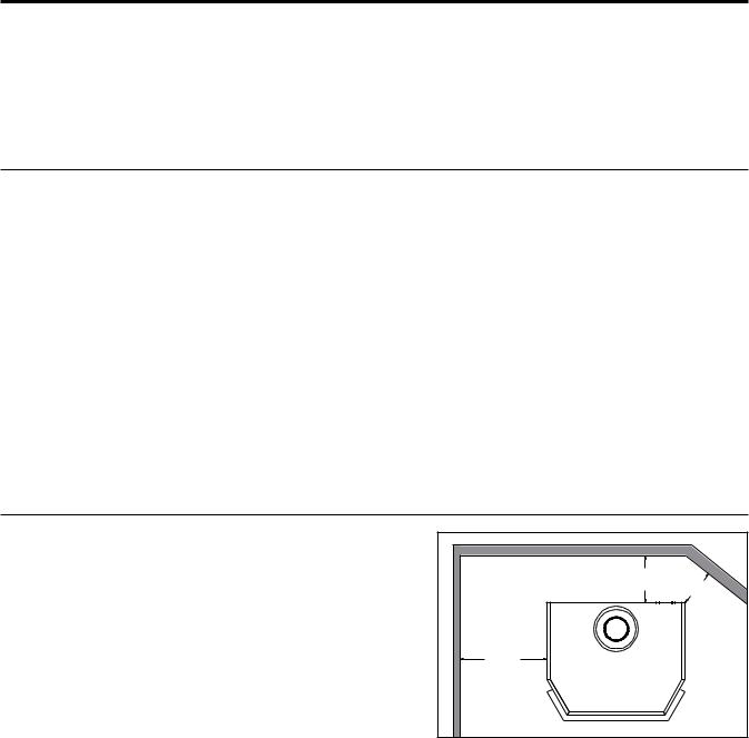
CLEARANCES TO COMBUSTIBLES:
A. Sidewall to unit |
10 inches |
(25.4 cm) |
B. Backwall to unit |
4 inches |
(10.2 cm) |
C. Corner to unit |
2 inches |
(5.1 cm) |
D. Combustibles to unit top |
22 inches |
(55.9 cm) |
E. Floor to unit |
0 inches |
(0 cm) |
F. Alcove maximum depth: |
48 inches |
(121.9 cm) |
CLEARANCES MUST BE SUFFICIENT TO ALLOW ACCESS FOR MAINTENANCE AND SERVICE.
|
|
|
|
||
|
||
|
|
|
|
|
Figure 13: Clearances to combustibles.
12
 Loading...