


 Loading...
SecureStack A2
Fast Ethernet Switches
Hardware Installation Guide
A2H124-24FX
P/N 9034174-01

Electrical Hazard: Only qualified personnel should perform installation procedures.
Riesgo Electrico: Solamente personal calificado debe realizar procedimientos de instalacion.
Elektrischer Gefahrenhinweis: Installationen sollten nur durch ausgebildetes und qualifiziertes Personal vorgenommen werden.
Notice
Enterasys Networks reserves the right to make changes in specifications and other information contained in this document and its web site without prior notice. The reader should in all cases consult Enterasys Networks to determine whether any such changes have been made.
The hardware, firmware, or software described in this document is subject to change without notice.
IN NO EVENT SHALL ENTERASYS NETWORKS BE LIABLE FOR ANY INCIDENTAL, INDIRECT, SPECIAL, OR CONSEQUENTIAL DAMAGES WHATSOEVER (INCLUDING BUT NOT LIMITED TO LOST PROFITS) ARISING OUT OF OR RELATED TO THIS DOCUMENT, WEB SITE, OR THE INFORMATION CONTAINED IN THEM, EVEN IF ENTERASYS NETWORKS HAS BEEN ADVISED OF, KNEW OF, OR SHOULD HAVE KNOWN OF, THE POSSIBILITY OF SUCH DAMAGES.
Enterasys Networks, Inc.
50 Minuteman Road
Andover, MA 01810
© 2007 Enterasys Networks, Inc. All rights reserved.
Part Number: 9034174 01 February 2007
ENTERASYS, ENTERASYS NETWORKS, ENTERASYS MATRIX, LANVIEW, NETSIGHT, WEBVIEW, and any logos associated therewith, are trademarks or registered trademarks of Enterasys Networks, Inc., in the United States and other countries.
All other product names mentioned in this manual may be trademarks or registered trademarks of their respective companies.
Documentation URL: http://www.enterasys.com/support/manuals
Documentacion URL: http://www.enterasys.com/support/manuals
Dokumentation im Internet: http://www.enterasys.com/support/manuals
i
REGULATORY COMPLIANCE INFORMATION
FEDERAL COMMUNICATIONS COMMISSION (FCC) NOTICE
This device complies with Part 15 of the FCC rules. Operation is subject to the following two conditions: (1) this device may not cause harmful interference, and (2) this device must accept any interference received, including interference that may cause undesired operation.
NOTE: This equipment has been tested and found to comply with the limits for a class A digital device, pursuant to Part 15 of the FCC rules. These limits are designed to provide reasonable protection against harmful interference when the equipment is operated in a commercial environment. This equipment uses, generates, and can radiate radio frequency energy and if not installed in accordance with the operator’s manual, may cause harmful interference to radio communications. Operation of this equipment in a residential area is likely to cause interference in which case the user will be required to correct the interference at his own expense.
WARNING: Changes or modifications made to this device which are not expressly approved by the party responsible for compliance could void the user’s authority to operate the equipment.
INDUSTRY CANADA NOTICE
This digital apparatus does not exceed the class A limits for radio noise emissions from digital apparatus set out in the Radio Interference Regulations of the Canadian Department of Communications.
Le présent appareil numérique n’émet pas de bruits radioélectriques dépassant les limites applicables aux appareils numériques de la class A prescrites dans le Règlement sur le brouillage radioélectrique édicté par le ministère des Communications du Canada.
CLASS A ITE NOTICE
WARNING: This is a Class A product. In a domestic environment this product may cause radio interference in which case the user may be required to take adequate measures.
CLASE A. AVISO DE ITE
ADVERTENCIA: Este es un producto de Clase A. En un ambiente doméstico este producto puede causar interferencia de radio en cuyo caso puede ser requerido tomar medidas adecuadas.
KLASSE A ITE ANMERKUNG
WARNHINWEIS: Dieses Produkt zählt zur Klasse A ( Industriebereich ). In Wohnbereichen kann es hierdurch zu Funkstörungen kommen, daher sollten angemessene Vorkehrungen zum Schutz getroffen werden.
PRODUCT SAFETY
This product complies with the following: UL 60950, CSA C22.2 No. 60950, 73/23/EEC, EN 60950, IEC 60950, EN 60825, 21 CFR 1040.10.
SEGURIDAD DEL PRODUCTO
El producto de Enterasys cumple con lo siguiente: UL 60950, CSA C22.2 No. 60950, 73/23/EEC, EN 60950, IEC 60950, EN 60825, 21 CFR 1040.10.
PRODUKTSICHERHEIT
Dieses Produkt entspricht den folgenden Richtlinien: UL 60950, CSA C22.2 No. 60950, 73/23/EEC, EN 60950, IEC 60950, EN 60825, 21 CFR 1040.10.
ii
ELECTROMAGNETIC COMPATIBILITY (EMC)
This product complies with the following: 47 CFR Parts 2 and 15, CSA C108.8, 89/336/EEC, EN 55022, EN 61000 3 2, EN 61000 3 3, EN 55024, AS/NZS CISPR 22, VCCI V 3.
COMPATIBILIDAD ELECTROMÁGNETICA (EMC)
Este producto de Enterasys cumple con lo siguiente: 47 CFR Partes 2 y 15, CSA C108.8, 89/336/EEC, EN 55022, EN 55024, EN 61000 3 2, EN 61000 3 3, AS/NZS CISPR 22, VCCI V 3.
ELEKTROMAGNETISCHE KOMPATIBILITÄT ( EMC )
Dieses Produkt entspricht den folgenden Richtlinien: 47 CFR Parts 2 and 15, CSA C108.8, 89/336/EEC, EN 55022, EN 61000 3 2, EN 61000 3 3, EN 55024, AS/NZS CISPR 22, VCCI V 3.
HAZARDOUS SUBSTANCES
This product complies with the requirements of European Directive, 2002/95/EC, Restriction of Hazardous Substances (RoHS) in Electrical and Electronic Equipment.
EUROPEAN WASTE ELECTRICAL AND ELECTRONIC EQUIPMENT (WEEE) NOTICE
In accordance with Directive 2002/96/EC of the European Parliament on waste electrical and electronic equipment (WEEE):
1.The symbol above indicates that separate collection of electrical and electronic equipment is required and that this product was placed on the European market after August 13, 2005, the date of enforcement for Directive 2002/96/EC.
2.When this product has reached the end of its serviceable life, it cannot be disposed of as unsorted municipal waste. It must be collected and treated separately.
3.It has been determined by the European Parliament that there are potential negative effects on the environment and human health as a result of the presence of hazardous substances in electrical and electronic equipment.
4.It is the users’ responsibility to utilize the available collection system to ensure WEEE is properly treated.
For information about the available collection system, please go to http://www.enterasys.com/services/support/ or contact Enterasys Customer Support at 353 61 705586 (Ireland).
iii

iv
VCCI NOTICE
This is a class A product based on the standard of the Voluntary Control Council for Interference by Information Technology Equipment (VCCI). If this equipment is used in a domestic environment, radio disturbance may arise. When such trouble occurs, the user may be required to take corrective actions.
BSMI EMC STATEMENT — TAIWAN
This is a class A product. In a domestic environment this product may cause radio interference in which case the user may be required to take adequate measures.
SAFETY INFORMATION
CLASS 1 LASER TRANSCEIVERS
SINGLE MODE NETWORK EXPANSION MODULES USE CLASS 1 LASER TRANSCEIVERS.
READ THE FOLLOWING SAFETY INFORMATION
BEFORE INSTALLING OR OPERATING THESE MODULES.
The Class 1 laser transceivers use an optical feedback loop to maintain Class 1 operation limits. This control loop eliminates the need for maintenance checks or adjustments. The output is factory set, and does not allow any user adjustment. Class 1 Laser transceivers comply with the following safety standards:
•21 CFR 1040.10 and 1040.11 U.S. Department of Health and Human Services (FDA).
•IEC Publication 825 (International Electrotechnical Commission).
•CENELEC EN 60825 (European Committee for Electrotechnical Standardization).
When operating within their performance limitations, laser transceiver output meets the Class 1 accessible emission limit of all three standards. Class 1 levels of laser radiation are not considered hazardous.
When the connector is in place, all laser radiation remains within the fiber. The maximum amount of radiant power exiting the fiber (under normal conditions) is 12.6 dBm or 55 x 10 6 watts.
Removing the optical connector from the transceiver allows laser radiation to emit directly from the optical port. The maximum radiance from the optical port (under worst case conditions) is 0.8 W cm 2 or 8 x 10³ W m2 sr 1.
Do not use optical instruments to view the laser output. The use of optical instruments to view laser output increases eye hazard. When viewing the output optical port, power must be removed from the network adapter.
v
DECLARATION OF CONFORMITY
Application of Council Directive(s): 89/336/EEC
73/23/EEC
Manufacturer’s Name: Enterasys Networks, Inc.
Manufacturer’s Address: 50 Minuteman Road
Andover, MA 01810
USA
European Representative Address: Enterasys Networks, Ltd.
Nexus House, Newbury Business Park
London Road, Newbury
Berkshire RG14 2PZ, England
Conformance to Directive(s)/Product Standards: EC Directive 89/336/EEC
EN 55022
EN 61000 3 2
EN 61000 3 3
EN 55024
EC Directive 73/23/EEC
EN 60950
EN 60825
Equipment Type/Environment: Networking Equipment, for use in a Commercial or Light Industrial Environment.
Enterasys Networks, Inc. declares that the equipment packaged with this notice conforms to the above directives.
vi
ENTERASYS NETWORKS, INC.
FIRMWARE LICENSE AGREEMENT
BEFORE OPENING OR UTILIZING THE ENCLOSED PRODUCT,
CAREFULLY READ THIS LICENSE AGREEMENT.
This document is an agreement (“Agreement”) between the end user (“You”) and Enterasys Networks, Inc. on behalf of itself and its Affiliates (as hereinafter defined) (“Enterasys”) that sets forth Your rights and obligations with respect to the Enterasys software program/firmware installed on the Enterasys product (including any accompanying documentation, hardware or media) (“Program”) in the package and prevails over any additional, conflicting or inconsistent terms and conditions appearing on any purchase order or other document submitted by You. “Affiliate” means any person, partnership, corporation, limited liability company, or other form of enterprise that directly or indirectly through one or more intermediaries, controls, or is controlled by, or is under common control with the party specified. This Agreement constitutes the entire understanding between the parties, and supersedes all prior discussions, representations, understandings or agreements, whether oral or in writing, between the parties with respect to the subject matter of this Agreement. The Program may be contained in firmware, chips or other media.
BY INSTALLING OR OTHERWISE USING THE PROGRAM, YOU REPRESENT THAT YOU ARE AUTHORIZED TO ACCEPT THESE TERMS ON BEHALF OF THE END USER (IF THE END USER IS AN ENTITY ON WHOSE BEHALF YOU ARE AUTHORIZED TO ACT, “YOU” AND “YOUR” SHALL BE DEEMED TO REFER TO SUCH ENTITY) AND THAT YOU AGREE THAT YOU ARE BOUND BY THE TERMS OF THIS AGREEMENT, WHICH INCLUDES, AMONG OTHER PROVISIONS, THE LICENSE, THE DISCLAIMER OF WARRANTY AND THE LIMITATION OF LIABILITY. IF YOU DO NOT AGREE TO THE TERMS OF THIS AGREEMENT OR ARE NOT AUTHORIZED TO ENTER INTO THIS AGREEMENT, ENTERASYS IS UNWILLING TO LICENSE THE PROGRAM TO YOU AND YOU AGREE TO RETURN THE UNOPENED PRODUCT TO ENTERASYS OR YOUR DEALER, IF ANY, WITHIN TEN (10) DAYS FOLLOWING THE DATE OF RECEIPT FOR A FULL REFUND.
IF YOU HAVE ANY QUESTIONS ABOUT THIS AGREEMENT, CONTACT ENTERASYS NETWORKS, LEGAL DEPARTMENT AT (978) 684 1000.
You and Enterasys agree as follows:
1.LICENSE. You have the non exclusive and non transferable right to use only the one (1) copy of the Program provided in this package subject to the terms and conditions of this Agreement.
2.RESTRICTIONS. Except as otherwise authorized in writing by Enterasys, You may not, nor may You permit any third party to:
(i)Reverse engineer, decompile, disassemble or modify the Program, in whole or in part, including for reasons of error correction or interoperability, except to the extent expressly permitted by applicable law and to the extent the parties shall not be permitted by that applicable law, such rights are expressly excluded.
Information necessary to achieve interoperability or correct errors is available from Enterasys upon request and upon payment of Enterasys’ applicable fee.
(ii)Incorporate the Program, in whole or in part, in any other product or create derivative works based on the Program, in whole or in part.
(iii)Publish, disclose, copy, reproduce or transmit the Program, in whole or in part.
(iv)Assign, sell, license, sublicense, rent, lease, encumber by way of security interest, pledge or otherwise transfer the Program, in whole or in part.
(v)Remove any copyright, trademark, proprietary rights, disclaimer or warning notice included on or embedded in any part of the Program.
vii
3.APPLICABLE LAW. This Agreement shall be interpreted and governed under the laws and in the state and federal courts of the Commonwealth of Massachusetts without regard to its conflicts of laws provisions. You accept the personal jurisdiction and venue of the Commonwealth of Massachusetts courts. None of the 1980 United Nations Convention on Contracts for the International Sale of Goods, the United Nations Convention on the Limitation Period in the International Sale of Goods, and the Uniform Computer Information Transactions Act shall apply to this Agreement.
4.EXPORT RESTRICTIONS. You understand that Enterasys and its Affiliates are subject to regulation by agencies of the U.S. Government, including the U.S. Department of Commerce, which prohibit export or diversion of certain technical products to certain countries, unless a license to export the Program is obtained from the U.S. Government or an exception from obtaining such license may be relied upon by the exporting party.
If the Program is exported from the United States pursuant to the License Exception CIV under the U.S. Export Administration Regulations, You agree that You are a civil end user of the Program and agree that You will use the Program for civil end uses only and not for military purposes.
If the Program is exported from the United States pursuant to the License Exception TSR under the U.S. Export Administration Regulations, in addition to the restriction on transfer set forth in Sections 1 or 2 of this Agreement, You agree not to (i) reexport or release the Program, the source code for the Program or technology to a national of a country in Country Groups D:1 or E:2 (Albania, Armenia, Azerbaijan, Belarus, Bulgaria, Cambodia, Cuba, Estonia, Georgia, Iraq, Kazakhstan, Kyrgyzstan, Laos, Latvia, Libya, Lithuania, Moldova, North Korea, the People’s Republic of China, Romania, Russia, Rwanda, Tajikistan, Turkmenistan, Ukraine, Uzbekistan, Vietnam, or such other countries as may be designated by the United States Government), (ii) export to Country Groups D:1 or E:2 (as defined herein) the direct product of the Program or the technology, if such foreign produced direct product is subject to national security controls as identified on the U.S. Commerce Control List, or (iii) if the direct product of the technology is a complete plant or any major component of a plant, export to Country Groups D:1 or E:2 the direct product of the plant or a major component thereof, if such foreign produced direct product is subject to national security controls as identified on the U.S. Commerce Control List or is subject to State Department controls under the U.S. Munitions List.
5.UNITED STATES GOVERNMENT RESTRICTED RIGHTS. The enclosed Program (i) was developed solely at private expense; (ii) contains “restricted computer software” submitted with restricted rights in accordance with section 52.227 19 (a) through (d) of the Commercial Computer Software Restricted Rights Clause and its successors, and (iii) in all respects is proprietary data belonging to Enterasys and/or its suppliers. For Department of Defense units, the Program is considered commercial computer software in accordance with DFARS section 227.7202 3 and its successors, and use, duplication, or disclosure by the Government is subject to restrictions set forth herein.
6.DISCLAIMER OF WARRANTY. EXCEPT FOR THOSE WARRANTIES EXPRESSLY PROVIDED TO YOU IN WRITING BY ENTERASYS, ENTERASYS DISCLAIMS ALL WARRANTIES, EITHER EXPRESS OR IMPLIED, INCLUDING BUT NOT LIMITED TO IMPLIED WARRANTIES OF MERCHANTABILITY, SATISFACTORY QUALITY, FITNESS FOR A PARTICULAR PURPOSE, TITLE AND NON INFRINGEMENT WITH RESPECT TO THE PROGRAM. IF IMPLIED WARRANTIES MAY NOT BE DISCLAIMED BY APPLICABLE LAW, THEN ANY IMPLIED WARRANTIES ARE LIMITED IN DURATION TO THIRTY (30) DAYS AFTER DELIVERY OF THE PROGRAM TO YOU.
7.LIMITATION OF LIABILITY. IN NO EVENT SHALL ENTERASYS OR ITS SUPPLIERS BE LIABLE FOR ANY DAMAGES WHATSOEVER (INCLUDING, WITHOUT LIMITATION, DAMAGES FOR LOSS OF BUSINESS, PROFITS, BUSINESS INTERRUPTION, LOSS OF BUSINESS INFORMATION, SPECIAL, INCIDENTAL, CONSEQUENTIAL, OR RELIANCE DAMAGES, OR OTHER LOSS) ARISING OUT OF THE USE OR INABILITY TO USE THE PROGRAM, EVEN IF ENTERASYS HAS BEEN ADVISED OF THE POSSIBILITY OF SUCH DAMAGES. THIS FOREGOING LIMITATION SHALL APPLY REGARDLESS OF THE CAUSE OF ACTION UNDER WHICH DAMAGES ARE SOUGHT.
viii
THE CUMULATIVE LIABILITY OF ENTERASYS TO YOU FOR ALL CLAIMS RELATING TO THE PROGRAM, IN CONTRACT, TORT OR OTHERWISE, SHALL NOT EXCEED THE TOTAL AMOUNT OF FEES PAID TO ENTERASYS BY YOU FOR THE RIGHTS GRANTED HEREIN.
8.AUDIT RIGHTS. You hereby acknowledge that the intellectual property rights associated with the Program are of critical value to Enterasys and, accordingly, You hereby agree to maintain complete books, records and accounts showing (i) license fees due and paid, and (ii) the use, copying and deployment of the Program. You also grant to Enterasys and its authorized representatives, upon reasonable notice, the right to audit and examine during Your normal business hours, Your books, records, accounts and hardware devices upon which the Program may be deployed to verify compliance with this Agreement, including the verification of the license fees due and paid Enterasys and the use, copying and deployment of the Program. Enterasys’ right of examination shall be exercised reasonably, in good faith and in a manner calculated to not unreasonably interfere with Your business. In the event such audit discovers non compliance with this Agreement, including copies of the Program made, used or deployed in breach of this Agreement, You shall promptly pay to Enterasys the appropriate license fees. Enterasys reserves the right, to be exercised in its sole discretion and without prior notice, to terminate this license, effective immediately, for failure to comply with this Agreement. Upon any such termination, You shall immediately cease all use of the Program and shall return to Enterasys the Program and all copies of the Program.
9.OWNERSHIP. This is a license agreement and not an agreement for sale. You acknowledge and agree that the Program constitutes trade secrets and/or copyrighted material of Enterasys and/or its suppliers. You agree to implement reasonable security measures to protect such trade secrets and copyrighted material. All right, title and interest in and to the Program shall remain with Enterasys and/or its suppliers. All rights not specifically granted to You shall be reserved to Enterasys.
10.ENFORCEMENT. You acknowledge and agree that any breach of Sections 2, 4, or 9 of this Agreement by You may cause Enterasys irreparable damage for which recovery of money damages would be inadequate, and that Enterasys may be entitled to seek timely injunctive relief to protect Enterasys’ rights under this Agreement in addition to any and all remedies available at law.
11.ASSIGNMENT. You may not assign, transfer or sublicense this Agreement or any of Your rights or obligations under this Agreement, except that You may assign this Agreement to any person or entity which acquires substantially all of Your stock or assets. Enterasys may assign this Agreement in its sole discretion. This Agreement shall be binding upon and inure to the benefit of the parties, their legal representatives, permitted transferees, successors and assigns as permitted by this Agreement. Any attempted assignment, transfer or sublicense in violation of the terms of this Agreement shall be void and a breach of this Agreement.
12.WAIVER. A waiver by Enterasys of a breach of any of the terms and conditions of this Agreement must be in writing and will not be construed as a waiver of any subsequent breach of such term or condition. Enterasys’ failure to enforce a term upon Your breach of such term shall not be construed as a waiver of Your breach or prevent enforcement on any other occasion.
13.SEVERABILITY. In the event any provision of this Agreement is found to be invalid, illegal or unenforceable, the validity, legality and enforceability of any of the remaining provisions shall not in any way be affected or impaired thereby, and that provision shall be reformed, construed and enforced to the maximum extent permissible. Any such invalidity, illegality or unenforceability in any jurisdiction shall not invalidate or render illegal or unenforceable such provision in any other jurisdiction.
14.TERMINATION. Enterasys may terminate this Agreement immediately upon Your breach of any of the terms and conditions of this Agreement. Upon any such termination, You shall immediately cease all use of the Program and shall return to Enterasys the Program and all copies of the Program.
ix
x

|
Contents |
About This Guide |
|
Who Should Use This Guide ............................................................................................................... |
xv |
How to Use This Guide ...................................................................................................................... |
xvi |
Related Documents ........................................................................................................................... |
xvi |
Conventions Used in This Guide ....................................................................................................... |
xvii |
Chapter 1: Introduction |
|
Overview ............................................................................................................................................ |
1-2 |
A2H124-24FX .............................................................................................................................. |
1-2 |
Stack Connections ....................................................................................................................... |
1-3 |
Redundant Power Supply Capability ........................................................................................... |
1-3 |
Connectivity ....................................................................................................................................... |
1-4 |
Management ...................................................................................................................................... |
1-5 |
Switch Configuration Using WebView ......................................................................................... |
1-5 |
Switch Configuration Using CLI Commands ............................................................................... |
1-5 |
Standards Compatibility ..................................................................................................................... |
1-5 |
LANVIEW Diagnostic LEDs ............................................................................................................... |
1-5 |
Getting Help ....................................................................................................................................... |
1-6 |
Chapter 2: Network Requirements |
|
100BASE-FX Multimode Fiber-Optic Network ................................................................................... |
2-1 |
1000BASE-FX Fiber-Optic Network ................................................................................................... |
2-2 |
1000BASE-T Twisted Pair Gigabit Ethernet Network ........................................................................ |
2-2 |
Chapter 3: Hardware Installation |
|
Considerations Prior to Installation .................................................................................................... |
3-2 |
Required Tools ................................................................................................................................... |
3-2 |
Unpacking the Switch ........................................................................................................................ |
3-2 |
Installing Optional Mini-GBICs ........................................................................................................... |
3-3 |
Removing the Mini-GBIC ............................................................................................................. |
3-6 |
Installing the Switch on a Flat Surface ............................................................................................... |
3-7 |
Installing the Rubber Feet ........................................................................................................... |
3-7 |
Guidelines for Flat Surface Installation ........................................................................................ |
3-8 |
Rack Mounting the Switch .............................................................................................................. |
3-10 |
Guidelines for Rackmount Installation ....................................................................................... |
3-10 |
Attaching Brackets and Installing in Rack ................................................................................. |
3-10 |
Connecting Stacking Cables ............................................................................................................ |
3-11 |
Configuring Switches in a Stack ...................................................................................................... |
3-13 |
About SecureStack A2 Switch Operation in a Stack ................................................................. |
3-13 |
Recommended Procedures for New and Existing Stacks ......................................................... |
3-14 |
xi
Connecting AC and RPS-SYS Power .............................................................................................. |
3-16 |
AC Power .................................................................................................................................. |
3-16 |
C2RPS-SYS Redundant Power System ................................................................................... |
3-18 |
Stack Initialization Overview ...................................................................................................... |
3-19 |
Connecting to Console Port for Local Management ........................................................................ |
3-20 |
What Is Needed ......................................................................................................................... |
3-20 |
Connecting to an IBM or Compatible Device ............................................................................. |
3-21 |
Connecting to a VT Series Terminal .......................................................................................... |
3-22 |
Connecting to a Modem ............................................................................................................ |
3-23 |
Connecting to the Network ............................................................................................................... |
3-24 |
Connecting Fiber-Optic Cables from A2H124-24FX to the Network ......................................... |
3-24 |
Connecting Fiber-Optic Cables to MT-RJ Mini-GBIC Ports ....................................................... |
3-26 |
Connecting Fiber-Optic Cables to LC Mini-GBIC Ports ............................................................. |
3-28 |
Connecting UTP Cables to RJ45 Mini-GBIC Ports .................................................................... |
3-30 |
Completing the Installation ............................................................................................................... |
3-33 |
Initial Logon to Switch Management .......................................................................................... |
3-33 |
Chapter 4: Troubleshooting
Using LANVIEW ................................................................................................................................. |
4-2 |
Troubleshooting Checklist .................................................................................................................. |
4-6 |
Using the Reset Password Switch ..................................................................................................... |
4-9 |
Appendix A: Specifications
Switch Specifications ........................................................................................................................ |
A-2 |
Mini-GBIC Input/Output Specifications ............................................................................................. |
A-3 |
Gigabit Ethernet Specifications ......................................................................................................... |
A-4 |
MGBIC-LC01/MGBIC-MT01 Specifications (1000BASE-SX) ..................................................... |
A-4 |
MGBIC-LC03 Specifications (1000BASE-SX) ............................................................................ |
A-5 |
MGBIC-LC09 Specifications (1000BASE-LX) ............................................................................ |
A-5 |
MGBIC-08 Specifications (1000BASE-ELX) .............................................................................. |
A-6 |
MGBIC-02 Specifications (1000BASE-T) ................................................................................... |
A-6 |
Console Port Pinout Assignments .................................................................................................... |
A-7 |
Regulatory Compliance ..................................................................................................................... |
A-7 |
Index
xii
Figures
1-1 |
A2H124-24FX Stackable Switch ............................................................................................ |
1-3 |
3-1 |
Mini-GBIC with RJ45 Connector ............................................................................................ |
3-4 |
3-2 |
Mini-GBIC with MT-RJ Connector.......................................................................................... |
3-5 |
3-3 |
Mini-GBIC with LC Connector ................................................................................................ |
3-6 |
3-4 |
Chassis Bottom, Rubber Feet Placement.............................................................................. |
3-8 |
3-5 |
Area Guidelines for Switch Installation on Flat Surface ......................................................... |
3-9 |
3-6 |
Attaching the Rackmount Brackets ...................................................................................... |
3-11 |
3-7 |
Fastening the Switch to the Rack......................................................................................... |
3-11 |
3-8 |
Stacking Cable Connections ................................................................................................ |
3-12 |
3-9 |
Switch Rear View ................................................................................................................. |
3-17 |
3-10 |
Accessing the RPS Connector............................................................................................. |
3-18 |
3-11 |
DB9 Male Console Port Pinout Assignments....................................................................... |
3-20 |
3-12 |
Connecting an IBM PC or Compatible ................................................................................. |
3-21 |
3-13 |
Connecting a VT Series Terminal ........................................................................................ |
3-22 |
3-14 |
Connecting to a Modem....................................................................................................... |
3-23 |
3-15 |
Connecting a Fiber-Optic Cable Segment to MT-RJ Port .................................................... |
3-25 |
3-16 |
Four-Wire Crossover Cable RJ45 Pinouts for 10/100BASE-TX .......................................... |
3-31 |
3-17 |
Four-Wire Straight-Through Cable RJ45 Pinouts for 10/100BASE-TX................................ |
3-31 |
3-18 |
Eight-Wire Crossover Cable RJ45 Pinouts for 10/100/1000BASE-TX................................. |
3-32 |
3-19 |
Eight-Wire Straight-Through Cable RJ45 Pinouts for 10/100/1000BASE-TX ...................... |
3-32 |
4-1 |
LANVIEW LEDs of A2H124-24FX ......................................................................................... |
4-2 |
4-2 |
Reset Password Switch ......................................................................................................... |
4-9 |
A-1 |
Console Port Pinout Assignments......................................................................................... |
A-7 |
Tables
1-1 |
Description of Mini-GBICs...................................................................................................... |
1-4 |
3-1 |
Contents of Switch Carton ..................................................................................................... |
3-2 |
4-1 |
LANVIEW LEDs ..................................................................................................................... |
4-3 |
4-2 |
Troubleshooting Checklist...................................................................................................... |
4-6 |
A-1 |
A2H124-24FX Switch Specifications..................................................................................... |
A-2 |
A-2 |
Mini-GBIC Input/Output Port Specifications .......................................................................... |
A-3 |
A-3 |
MGBIC-LC01/MGBIC-MT01 Optical Specifications .............................................................. |
A-4 |
A-4 |
MGBIC-LC01/MGBIC-MT01 Operating Range ..................................................................... |
A-4 |
A-5 |
MGBIC-LC03 Optical Specifications ..................................................................................... |
A-5 |
A-6 |
MGBIC-LC03 Operating Range ............................................................................................ |
A-5 |
A-7 |
MGBIC-LC09 Optical Specifications ..................................................................................... |
A-5 |
A-8 |
MGBIC-LC09 Operating Range ............................................................................................ |
A-5 |
A-9 |
MGBIC-08 Optical Specifications.......................................................................................... |
A-6 |
A-10 |
MGBIC-08 Operating Range................................................................................................. |
A-6 |
A-11 |
MGBIC-02 Specifications ...................................................................................................... |
A-6 |
A-12 |
Compliance Standards.......................................................................................................... |
A-7 |
xiii
xiv
About This Guide
This guide provides an overview, installation and troubleshooting instructions, and specifications for the Enterasys® SecureStack A2H124 24FX stackable Ethernet switch.
For information about the Command Line Interface (CLI) set of commands used to configure and manage the switch, refer to the Enterasys Networks® SecureStack A2 Configuration Guide.
Note: In this guide, the following terms are used:
• Switch refers to an A2H124-24FX unless otherwise noted.
•MGBIC (Mini-Gigabit Interface Card) refers to optional small form plugable (SFP) interface modules that plug into the fixed front panel MGBIC slots.
Important Notice
Depending on the firmware version used in the A2H124-24FX switch, some features described in this document may not be supported. Refer to the Release Notes shipped with the SecureStack A2 to determine which features are supported.
Who Should Use This Guide
This guide is intended for a network administrator responsible for installing and setting up the stackable switches.
Electrical Hazard: Only qualified personnel should perform installation procedures.
Riesgo Electrico: Solamente personal calificado debe realizar procedimientos de instalacion.
Elektrischer Gefahrenhinweis: Installationen sollten nur durch ausgebildetes und qualifiziertes Personal vorgenommen werden.
SecureStack A2 Installation Guide xv

How to Use This Guide
How to Use This Guide
Read through this guide completely to familiarize yourself with its contents and gain an understanding of the features and capabilities of the stackable Ethernet switch. A general knowledge of data communications networks is helpful when setting up the switches.
This preface provides an overview of this guide and the SecureStack A2 manual set, a brief summary of each chapter and defines the conventions used throughout this guide. To locate information concerning various subjects in this guide, refer to the following table:
For... |
Refer to... |
|
|
An overview of the SecureStack A2 features and |
Chapter 1, Introduction |
how to obtain technical support |
|
|
|
Network requirements that must be met before |
Chapter 2, Network Requirements |
installing the SecureStack A2 |
|
|
|
Instructions to install the SecureStack A2 on a flat |
Chapter 3, Hardware Installation |
surface or in a standard 19-inch rack and |
|
configure the SecureStack A2 in a stacked |
|
configuration |
|
|
|
Troubleshooting installation problems and |
Chapter 4, Troubleshooting |
diagnosing network/operational problems using |
|
the LANVIEW LEDs |
|
|
|
Specifications, environmental requirements, and |
Appendix A, Specifications |
physical properties of the SecureStack A2 and |
|
optional Mini-GBICs |
|
|
|
Related Documents
The documents listed below provide the necessary information to install and configure the switch and can be obtained from the World Wide Web in Adobe Acrobat Portable Document Format (PDF) at the following site:
http://www.enterasys.com/support/manuals
•SecureStack A2 Configuration Guide describes how to use the Command Line Interface (CLI) to set up and manage the A2 switches.
•Cabling Guide provides information concerning network cabling, dB loss, and other cabling specifications and usage. Unlike the SecureStack A2 Configuration Guide, the Cabling Guide is not listed alphabetically on the web site. Instead, it is under the
Overview Guides link.
xviAbout This Guide

Conventions Used in This Guide
Conventions Used in This Guide
The following conventions are used in this guide:
Note: Calls the reader’s attention to any item of information that may be of special importance.
Caution: Contains information essential to avoid damage to the equipment.
Precaución: Contiene información esencial para prevenir dañar el equipo.
Achtung: Verweißt auf wichtige Informationen zum Schutz gegen Beschädigungen.
Electrical Hazard: Warns against an action that could result in personal injury or death due to an electrical hazard.
Riesgo Electrico: Advierte contra una acción que pudiera resultar en lesión corporal o la muerte debido a un riesgo eléctrico.
Elektrischer Gefahrenhinweis: Warnung vor sämtlichen Handlungen, die zu Verletzung von Personen oder Todesfällen – hervorgerufen durch elektrische Spannung – führen können!
Warning: Warns against an action that could result in personal injury or death.
Advertencia: Advierte contra una acción que pudiera resultar en lesión corporal o la muerte.
Warhinweis: Warnung vor Handlungen, die zu Verletzung von Personen oder gar
Todesfällen führen können!
SecureStack A2 Installation Guide xvii

Conventions Used in This Guide
xviii About This Guide
1
Introduction
This chapter introduces the A2H124 24FX stackable switch.
Important Notice
Depending on the firmware version used in the SecureStack A2, some features described in this document may not be supported. Refer to the Release Notes shipped with the A2H124-24FX to determine which features are supported.
For information about... |
Refer to page... |
|
|
Overview |
1-2 |
|
|
Connectivity |
1-4 |
|
|
Management |
1-5 |
|
|
Standards Compatibility |
1-5 |
|
|
LANVIEW Diagnostic LEDs |
1-5 |
|
|
Getting Help |
1-6 |
|
|
SecureStack A2 Installation Guide 1-1
Overview
Overview
The A2H124 24FX is a stackable Fast Ethernet switch, which can be adapted and scaled to help meet your network needs. This switch provides a management platform and uplinks to a network backbone for a stacked group of up to eight A2 switches. The two built in Small Form Pluggable (SFP) interface slots provide you with the option of installing Mini GBICs. The various versions of hot swappable Mini GBICs provide you with the flexibility to install interfaces that support:
•1000BASE T Ethernet over copper connections for 10/100/1000 Mbps
•1000BASE SX/LX/ELX fiber optic connections for 1 Gbps fiber optic connections
The switch also supports the use of a redundant DC power supply to help prevent downtime due to an internal power supply failure in the switch or AC power source.
You can install the SecureStack A2 on a flat surface or into a standard 19 inch rack with user supplied mounting hardware, and configure the SecureStack A2 functions using the WebView™ application, CLI switching commands, and/or SNMP.
A2H124-24FX
The A2H124 24FX (Figure 1 1) has several types of front panel ports and rear panel connections, which include:
•Twenty Four 100BASE FX multimode MT RJ Ports
•Two SFP slots labeled port 27 and 28 that support
–optional Mini GBIC 1000BASE T Ethernet over copper interface connections for 10/100/1000 Mbps operation
–optional 1000BASE SX/LX/ELX fiber optic connections
•Two 1000BASE T RJ45 Ports which can be used in a stack configuration as well as standard Gigabit Ethernet switch ports when configured as a standalone switch.
•Rear panel Redundant Power Supply connector for a redundant power supply connection. The switch connects to an Enterasys C2RPS SYS using a C2RPS PSM Cable.
Caution: The A2H124-24FX is not a PoE-compliant device. Do not connect a SecureStack C2 PoE Redundant Power System (C2RPS-POE) to the power connector. Otherwise, damage to the device may result.
Precaución: El dispositivo A2H124-24FX no cumple con el estándar PoE. No conecte una fuente de poder redundante (RPS) SecureStack C2 PoE (C2RPS-POE) al cable de corriente directa. De lo contrario, el dispositivo puede dañarse.
Note: The 1000BASE-T built-in RJ45 stacking ports 25 and 26 on the A2H124-24FX can be configured as standard 10/100/1000BASE-T switch ports, using the command “set switch stackport <ethernet | stack>” when the unit is in standalone mode (not stacked).
1-2 Introduction
Overview
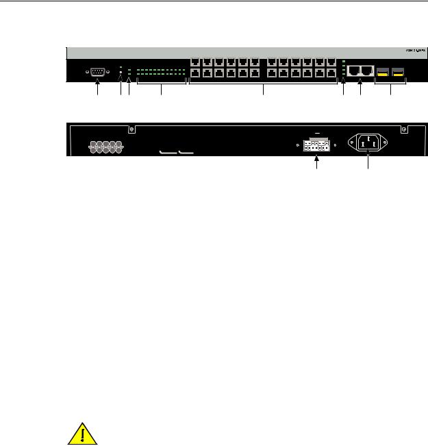
Figure 1-1 A2H124-24FX Stackable Switch
Front
|
|
|
|
|
|
|
|
|
|
|
|
|
1 |
3 |
5 |
7 |
9 |
11 |
13 |
15 |
17 |
19 |
21 |
23 |
|
|
|
|
|
|
|
|
|
|
|
|
|
|
|
|
|
|
|
|
|
|
|
|
|
|
|
25 |
25/Up |
26/Down |
|
|
|
|
|
|
|
|
|
|
|
|
|
|
|
|
|
|
|
|
|
|
|
|
|
|
|
||
Console |
CPU |
1 |
3 |
5 |
7 |
9 |
11 |
13 |
15 |
17 |
19 |
21 |
23 |
|
|
|
|
|
|
|
|
|
|
26 |
|
27 |
28 |
|
|
|
|
|
|
|
|
|
|
|
27 |
|
|
|
|||||||||||||
|
|
MGR |
|
|
|
|
|
|
|
|
|
|
|
|
|
|
|
|
|
|
|
|
|
|
|
|
|
|
|
RPS |
4 |
6 |
8 |
10 |
12 |
14 |
16 |
18 |
20 |
22 |
24 |
|
|
|
|
|
|
|
|
|
|
28 |
|
|
|
|
|
2 |
|
|
|
|
|
|
|
|
|
|
|
|
|
|
|||||||||||
|
|
|
|
|
|
|
|
|
|
|
|
|
|
|
|
|
|
|
|
|
|
|
|
|
|
Stack |
|
|
|
|
|
|
|
|
|
|
|
|
|
|
2 |
4 |
6 |
8 |
10 |
12 |
14 |
16 |
18 |
20 |
22 |
24 |
|
|
|
À ÁÂ Ã |
Ä |
Å Æ Ç |
Back |
|
|
|
Redundant Power Supply |
|
|
DC Line 12V |
/13A MAX. |
|
|
AC LINE |
|
|
100-240 VAC |
|
|
50-60 Hz |
|
|
1 A MAX. |
MAC ADDRESS SERIAL NO.
|
|
|
È |
É |
1 |
DB9 RS232 Console port connector |
6 |
Stack and MGBIC port status LEDs |
|
2 |
Recessed password reset button |
7 |
RJ45 ports for stack connections |
|
3 |
Stack Unit status LEDS |
8 |
SFP interface slots (Mini-GBICs) |
|
4 |
MT-RJ port status LEDS |
9 |
C2RPS-SYS connection |
|
5 |
MT-RJ fiber-optic ports |
10 |
AC power input connector |
|
Stack Connections
The switch has front panel RJ45 ports 25 and 26 for connections in a stack configuration. The stacking cables used for the connections are standard Category 5 or better UTP cable.
Redundant Power Supply Capability
The SecureStack A2 has power supply redundancy capability when connected to an optional external redundant power supply (RPS). If the internal power supply fails, the RPS assumes the entire load of the SecureStack A2 without interrupting network traffic. The internal power supply and RPS each have their own AC power connection, which enables the connection of each power supply to a different AC power circuit for additional AC power source redundancy.
Caution: The A2H124-24FX is not a PoE-compliant device. Do not connect a SecureStack PoE Redundant Power System (C2RPS-POE) to the power connector. Otherwise, damage to the device may result.
Precaución: Los dispositivos A2H124-24FX no cumplen con el estándar PoE (power over ethernet). No conecte una fuente de poder redundante (RPS) SecureStack PoE (C2RPS-POE) al cable de corriente. De lo contrario, el dispositivo puede dañarse.
SecureStack A2 Installation Guide 1-3

Connectivity
Connectivity
The SecureStack A2 switch connects to Ethernet networks or workstations by way of the fixed front panel MT RJ ports and two uplink ports that support optional Mini GBICs.
At the time of this printing, the Mini GBICs that are available from Enterasys and supported by A2 switch are described in Table 1 1. These Mini GBICs meet or exceed the IEEE 802.3z 1998 standard.
Table 1-1 Description of Mini-GBICs
Mini-GBIC Specification
MGBIC-LC01 Provides one 1000BASE-SX compliant LC fiber-optic multimode port and a standard LC connector. For optical and operating range specifications, refer to “MGBIC-LC01/MGBIC-MT01 Specifications (1000BASE-SX)” on page A-4.
MGBIC-LC03 Provides one 1000BASE-SX Long Haul LC fiber-optic multimode port with a standard LC duplex connector. For optical and operating range specifications, refer to “MGBIC-LC03 Specifications (1000BASE-SX)” on page A-5.
MGBIC-LC09 Provides one 1000BASE-LX compliant LC fiber-optic single-mode port with a standard LC connector. For optical and operating range specifications, refer to “MGBIC-LC09 Specifications (1000BASE-LX)” on page A-5.
MGBIC-MT01 Provides one 1000BASE-SX compliant LC fiber-optic multimode port with a standard MT-RJ connector. For optical and operating range specifications, refer to “MGBIC-LC01/MGBIC-MT01 Specifications (1000BASE-SX)” on page A-4.
MGBIC-08 Provides one 1000BASE-ELX compliant LC fiber-optic single-mode port with a standard LC connector. For optical and operating range specifications, refer to “MGBIC-08 Specifications (1000BASE-ELX)” on page A-6.
MGBIC-02 Provides one RJ45 copper connection that is compliant with the 1000BASE-T standard RJ45 connector. For operating range specifications, refer to “MGBIC-02 Specifications (1000BASE-T)” on page A-6.
1-4 Introduction

Management
Management
Management of the module can be either in band or out of band. In band remote management is possible using Telnet, Enterasys Networks’ NetSight® management application, or the WebView application. Out of band management is provided through the DB9 Console port connector on the front panel using a VT100 terminal or a VT100 terminal emulator.
Switch Configuration Using WebView
Enterasys Networks’ HTTP based Web management application (WebView) is an intuitive web tool for simple management tasks.
Switch Configuration Using CLI Commands
The CLI commands enable you to perform more complete SecureStack A2 configuration management tasks.
For CLI command set information and how to configure the module, refer to the
SecureStack A2 Configuration Guide.
Standards Compatibility
The A2H128 24FX is fully compliant with the IEEE 802.3 2002, 802.3ae 2002, 802.1D 1998, and 802.1Q 1998 standards. The SecureStack A2 provides IEEE 802.1D 1998 Spanning Tree Algorithm (STA) support to enhance the overall reliability of the network and protect against “loop” conditions.
LANVIEW Diagnostic LEDs
LANVIEW diagnostic LEDs serve as an important troubleshooting aid by providing an easy way to observe the status of individual ports and overall network operations.
SecureStack A2 Installation Guide 1-5
Loading...