


INSTALLATION INSTRUCTIONS
AND
OWNER'S MANUAL
The Classic Cast Iron Stoves |
CAST IRON |
|
UNVENTED ROOM HEATER |
|
MODEL |
|
CIVF-25-21 |
|
EFFECTIVE DATE |
|
AUGUST 2006 |
This appliance may be installed in an aftermarket, permanentlylocated,manufactured(mobile)home, where not prohibited by local codes.
This appliance is only for use with the type of gas indicated on the rating plate. This appliance is not convertible for use with other gases.
WARNING: If the information in these instructions are not followed exactly, a fire orexplosion may result causing property damage, personal injury or loss of life.
—Do not store or use gasoline or other flammable vapors and liquids in the vicinity of this or any other appliance.
—WHAT TO DO IFYOU SMELL GAS
•Do not try to light any appliance.
•Do not touch any electrical switch; do not use any phone in your building.
•Immediately call your gas supplier from a neighbor’s phone. Follow the gas supplier’s instructions.
•If you cannot reach your gas supplier, call the fire department.
—Installation and service must be performed by a qualified installer, service agency or the gas supplier.
Installer: Leave this manual with the appliance.
Consumer:Retain this manual for future reference.
This is an unvented gas-fired heater. It uses air (oxygen) from the room in which it is installed. Provisionsforadequatecombustionandventilation air must be provided. Refer to page 6.
WARNING: If not installed, operated and maintained in accordance with the manufacturer's instructions, this product could expose you to substances in fuel or from fuel combustion which can cause death or serious illness.
WATERVAPOR:ABY-PRODUCTOFUNVENT- ED ROOM HEATERS
Watervaporis a by-product of gas combustion.An unventedroomheaterproducesapproximatelyone
(1) ounce (30ml) of water for every 1,000 BTU's (.3KW's) of gas input per hour. Refer to page 6.
16938-3-0806 |
Page 1 |

TABLE OF CONTENTS |
|
SECTION |
PAGE |
Important Safety Information................................................................................................. |
3 |
Safety Information for Users of LP Gas................................................................................. |
4 |
Introduction............................................................................................................................ |
5 |
Specifications ......................................................................................................................... |
5 |
Water Vapor: A By-Product of Unvented Room Heaters....................................................... |
6 |
Provisions for Adequate Combustion and Ventilation Air .................................................... |
6 |
Gas Supply ............................................................................................................................. |
7 |
Clearances ............................................................................................................................. |
8 |
Appliance Hardware Package ................................................................................................ |
9 |
Assembly of Stove Casting ............................................................................................ |
10-12 |
Optional Stone Inlay Installation.......................................................................................... |
13 |
Wire Channel Installation..................................................................................................... |
13 |
Log Placement...................................................................................................................... |
14 |
Operating Guidelines............................................................................................................ |
14 |
Lighting Instructions ........................................................................................................... |
15 |
Pilot Flame Characteristics................................................................................................... |
16 |
Main Burner Flame Characteristics...................................................................................... |
17 |
Wiring ............................................................................................................................ |
18-19 |
Maintenance ......................................................................................................................... |
19 |
Troubleshooting............................................................................................................. |
20-21 |
How To Order Repair Parts.................................................................................................. |
21 |
Parts List for Stove Casting.................................................................................................. |
22 |
Parts List for CIVF-25-21 ................................................................................................... |
22 |
Parts View for Stove Casting................................................................................................ |
23 |
Parts View for CIVF-25-21 ................................................................................................ |
24 |
Optional Blower Installation Instructions ..................................................................... |
25-26 |
Service Notes........................................................................................................................ |
27 |
Page 2 |
16938-3-0806 |

IMPORTANT SAFETY INFORMATION
THIS IS A HEATING APPLIANCE
DO NOT OPERATE THIS APPLIANCE WITHOUT FRONT PANEL INSTALLED.
• Anunventedroomheaterhavinganinputratingofmorethan |
|
Any safety screen or guard removed for servicing an appli- |
|
|
6,000 Btu per hour shall not be installed in a bathroom. |
|
ance must be replaced prior to operating the heater. |
• |
An unvented room heater having an input rating of more |
• DOmakeaperiodicvisualcheckofpilotandburners.Clean |
|
|
than 10,000 Btu perhourshall not be installed in a bedroom |
|
and replace damaged parts. |
|
or bathroom. |
• |
DO NOT use this room heater if any part has been under |
• |
Due to high temperatures, the appliance should be located |
|
water. Immediately call a qualified service technician to |
|
out of traffic and away from furniture and draperies. |
|
inspecttheroomheaterandtoreplaceanypartofthecontrol |
• Children and adults should be alerted to the hazard of high |
|
system and any gas control which has been under water. |
|
|
surface temperature and should stay away to avoid burns |
• |
Due to high surface temperatures, keep children, clothing |
|
or clothing ignition. |
|
and furniture away. |
• |
Young children should be carefully supervised when they |
• Under no circumstances should any solid fuels (wood, coal, |
|
|
are in the same room with the appliance. |
|
paper or cardboard etc.) be used in this appliance. |
• |
Do not place clothing or other flammable material on or |
• |
The flow of combustion and ventilation air must not be |
|
near the appliance. |
|
obstructed in any way. |
• Keep burner and control compartment clean. |
• |
WARNING: Failure to keep the primary air opening(s) of |
|
• |
Installation and repair should be done by a QUALIFIED |
|
theburner(s)cleanmayresultinsootingandpropertydam- |
|
SERVICE PERSON. The appliance should be inspected |
|
age. |
|
before use and at least annually by a professional service |
• Keepapplianceareaclearandfreefromcombustiblemateri- |
|
|
person. More frequent cleaning may be required due to |
|
als, gasoline and other flammable vapors and liquids. |
|
excessive lint from carpeting, bedding materials, etc. It |
• |
WARNING: Do not use a blower insert, heat exchanger |
|
is imperative that control compartments, burners and |
|
insert or other accessory not approved for use with heater. |
|
circulating air passageways of the appliance be kept clean. |
|
|
• WARNING: ANY CHANGE TO THIS HEATER OR ITS |
|
|
|
|
CONTROLS CAN BE DANGEROUS. |
|
|
|
|
|
|
|
WARNING |
||
|
When used without adequate combustion and ventilation air, |
Early signs of carbon monoxide poisoning resemble the flu, |
|
|
heater may give off CARBON MONOXIDE, an odorless, |
with headache, dizziness and/or nausea. If you have these |
|
|
poisonous gas. |
signs, heater may not be working properly. Get fresh air at |
|
|
|
|
once! Have heater serviced. |
|
Do not install heater until all necessary provisions are |
|
|
|
|
Some people — pregnant women, persons with heart or lung |
|
|
made forcombustion and ventilation air. Consult the writ- |
|
|
|
ten instructions provided with the heater for information |
|
disease, anemia, those under the influence of alcohol , those |
|
concerning combustion and ventilation air. In the absence |
|
at high altitudes — are more affected by carbon monoxide |
|
of instructions, refer to the National Fuel Gas Code,ANSI |
|
than others. |
|
Z223.1, Section 5.3 or applicable local codes. |
|
The pilot light safety system senses the depletion of oxygen at |
|
This heater is equipped with a PILOT LIGHT SAFETY |
its location. If this heater is installed in a structure having a |
|
|
SYSTEM designed to turn off the heater if not enough fresh |
high vertical dimension, the possibility exists that the oxygen |
|
|
air is available. |
supplyatthehigherlevelswillbelessthanthatattheheater.In |
|
|
|
|
this type of application, a fan to circulate the structure airwill |
|
DO NOT TAMPER WITH PILOT LIGHT SAFETY |
|
|
|
|
minimize this effect. The use of this fan will also improve the |
|
|
SYSTEM! |
|
|
|
|
comfort level in the structure. When a fan is used to circulate |
|
|
If heater shuts off, do not relight until you provide fresh air. |
air, it should be located so that the air flow is not directed at |
|
|
If heaterkeeps shutting off, have it serviced. Keep burnerand |
the burner. |
|
|
control compartment clean. |
|
|
|
CARBON MONOXIDE POISONING MAY LEAD TO |
|
|
|
DEATH. |
|
|
|
|
|
|
|
|
|
|
16938-3-0806 |
Page 3 |

SAFETY INFORMATION FOR USERS OF LP-GAS
Propane (LP-Gas) is a flammable gas which can cause fires and explosions. In its natural state, propane is odorless and colorless. You may not know all the following safety precautions which can protect both you and your family from an accident. Read them carefully now, then review them point
by point with the members of your household. Someday when theremaynotbeaminutetolose,everyone'ssafetywilldepend on knowing exactly what to do. If, after reading the following information, you feel you still need more information, please contact your gas supplier.
LP-GAS WARNING ODOR
If a gas leak happens, you should be able to smell the gas because of the odorant put in the LP-Gas. That's your signal to go into immediate action!
•Donotoperateelectricswitches,lightmatches,useyourphone. Do not do anything that could ignite the gas.
•Get everyone out of the building, vehicle, trailer, or area. Do that IMMEDIATELY.
•Close all gas tank or cylinder supply valves.
•LP-Gas is heavier than air and may settle in low areas such as basements. When you have reason to suspect a gas leak, keep out of basements and other low areas. Stay out until firefighters declare them to be safe.
•Use your neighbor's phone and call a trained LP-Gas service person and the fire department. Even though you may not continue to smell gas, do not turn on the gas again. Do not re-enter the building, vehicle, trailer, or area.
•Finally, let the service man and firefighters check for escaped gas. Have them air out the area before you return. Properly trainedLP-Gasservicepeopleshouldrepairtheleak,thencheck and relight the gas appliance for you.
NO ODOR DETECTED - ODOR FADE
Some people cannot smell well. Some people cannot smell the odor of the chemical put into the gas.You must find out if you can smell the odorant in propane. Smoking can decrease your ability to smell. Being around an odor for a time can affect your sensitivity or ability to detect that odor. Sometimes other odors in the area mask the gas odor. People may not smell the gas odor or their minds are on something else. Thinking about smelling a gas odor can make it easier to smell.
TheodorantinLP-gasiscolorless,anditcanfadeundersome circumstances. For example, if there is an underground leak, the movement of the gas through soil can filter the odorant. Odorants
in LP-Gas also are subject to oxidation. This fading can occur if there is rust inside the storage tank or in iron gas pipes.
Theodorantinescapedgascanadsorborabsorbontoorintowalls, masonry and other materials and fabrics in a room. That will take some of the odorant out of the gas, reducing its odor intensity.
LP-Gas may stratify in a closed area, and the odor intensity could vary at different levels. Since it is heavier than air, there may be more odor at lower levels.Always be sensitive to the slightest gas odor.Ifyoudetectanyodor,treatitasaseriousleak.Immediately go into action as instructed earlier.
SOME POINTS TO REMEMBER
•Learn to recognize the odor of LP-gas. Your local LP-Gas Dealer can give you a "Scratch and Sniff" pamphlet. Use it to find out what the propane odor smells like. If you suspect that your LP-Gas has a weak or abnormal odor, call your LP-Gas Dealer.
•Ifyouarenotqualified,donotlightpilotlights,performservice, or make adjustments to appliances on the LP-Gas system. If you are qualified, consciously think about the odor of LP-Gas prior to and while lighting pilot lights or performing service or making adjustments.
•Sometimes a basement or a closed-up house has a musty smell that can cover up the LP-Gas odor. Do not try to light pilot lights, perform service, or make adjustments in an area where the conditions are such that you may not detect the odor if there has been a leak of LP-Gas.
•Odor fade, due to oxidation by rust or adsorption on walls of new cylinders and tanks, is possible. Therefore, people should be particularly alert and careful when new tanks or cylinders are placed in service. Odor fade can occur in new tanks, or
reinstalled old tanks, if they are filled and allowed to set too long before refilling. Cylinders and tanks which have been out of service for a time may develop internal rust which will cause odor fade. If such conditions are suspected to exist, a periodic snifftestofthegasisadvisable.Ifyouhaveanyquestionabout the gas odor, call your LP-gas dealer.Aperiodic sniff test of the LP-gas is a good safety measure under any condition.
•If, at any time, you do not smell the LP-Gas odorant and you think you should, assume you have a leak. Then take the same immediate action recommended above for the occasion when you do detect the odorized LP-Gas.
•If you experience a complete "gas out," (the container is under no vapor pressure), turn the tank valve off immediately. If the container valve is left on, the container may draw in some air throughopeningssuchaspilotlightorifices.Ifthisoccurs,some new internal rusting could occur. If the valve is left open, then treatthecontainerasanewtank.Alwaysbesureyourcontainer is under vapor pressure by turning it off at the container before it goes completely empty or having it refilled before it is completely empty.
Page 4 |
16938-3-0806 |

INTRODUCTION
Always consult your local Building Department regarding regulations, codes or ordinances which apply to the installation of an unvented room heater.
This appliance may be installed in an aftermarket* permanently located, manufactured (mobile) home, where not prohibited by state or local codes.
*Aftermarket: Completion of sale, not for purpose of resale, from the manufacturer.
This appliance is only for use with the type of gas indicated on the rating plate.
Instructions to Installer
1.Installer must leave instruction manual with owner after installation.
2.Installer must have owner fill out and mail warranty card supplied with unvented room heater.
3.Installershouldshowownerhowtostartandoperateunvented room heater.
This CIVF-25 is design certified in accordance with American National Standards Institute Z21.11.2 by the Canadian Standards Association as an Unvented Room Heater and should be installed according to these instructions.
Attention: During initial use of ceramic log you will detect an odorastheceramiclogiscured.Also,duringthecuringprocess the ceramic log will burn with a yellow flame.
Any alteration of the original design, installed other than as shown in these instructions or use with a type of gas not shown on the rating plate is the responsibility of the person and company making the change.
Warning:Thisapplianceisequippedfor(naturalorpropane) gas. Field conversion is not permitted.
Important
AllcorrespondenceshouldrefertocompleteModelNumber,Serial Number and type of gas.
Notice:Duringinitialfiringofthisunit,itspaintwillbakeout,and smokewilloccur.Topreventtriggeringofsmokealarms,ventilate the room in which the unit is installed.
Qualified Installing Agency
Installationandreplacementofgaspiping,gasutilizationequipment or accessories and repair and servicing of equipment shall be performedonlybyaqualifiedagency.Theterm"qualifiedagency" meansanyindividual,firm,corporationorcompanywhicheitherin personorthrougharepresentativeisengagedinandisresponsible for (a) the installation or replacement of gas piping or (b) the connection, installation, repair or servicing of equipment, who is experienced in such work, familiar with all precautions required andhascompliedwithalltherequirementsoftheauthorityhaving jurisdiction.
State of Massachusetts: The installation must be made by a licensed plumber or gas fitter in the Commonwealth of Massachusetts.
Sellers of unvented propane or natural gas-fired supplemental roomheatersshallprovidetoeachpurchaseracopyof527CMR 30 upon sale of the unit.
The installation must conform with local codes or, in the absence of local codes, with the National Fuel Gas Code, ANSI Z223.1/ NFPA 54.*
*Available from the American National Standards Institute, Inc., 11 West 42nd St., New York, N.Y. 10036.
High Altitudes
Foraltitudes/elevationsabove2,000feet(610m),ratingsshouldbe reduced at the rate of 4 percent for each 1,000 feet (305m) above sea level. Contact the manufacturer or your gas company before
changing spud/orifice size.
SPECIFICATIONS
Model |
CIVF-25 |
Input BTU/HR (KW/H) Maximum |
30,000 (8.8) |
BTU/HR (KW/H) Minimum |
21,000 (6.2) |
Height |
27 3/4" (70.5cm) |
Width |
25 1/2" (64.8cm) |
Depth |
15 1/2" (39.4cm) |
Gas Inlet |
3/8" (9.5mm) |
Stove Casting (Must be ordered with Firebox)
CIFB-1 |
Flat Black |
CIPB-1 |
Porcelain Black |
CIPG-1 |
Porcelain Green |
CIPS-1 |
Porcelain Sand |
CIPN-1 |
Porcelain Navy |
CIPR-1 |
Porcelain Red |
Accessories
TMV |
Millivolt Wall Thermostat - Reed Switch |
FRBC-1 |
Battery Operated Remote Control |
FRBTC-1 Battery Operated Remote Control w/Thermostat
FREC-1 |
Electric Remote Control |
|
FWS-1 |
Wall Switch |
|
CIB-2 |
Automatic BLower |
|
Stone Inlay Replaces Standard Grill Top |
||
CII-2 |
Stone Inlay |
Empress Green |
CII-3 |
Stone Inlay |
Hunan Jade |
CII-4 |
Stone Inlay |
Gray Botticino |
CII-5 |
Stone Inlay |
Azul |
CII-6 |
Stone Inlay |
Salome |
CII-7 |
Stone Inlay |
Black Swan |
16938-3-0806 |
Page 5 |

WATER VAPOR: A BY-PRODUCT OF UNVENTED ROOM HEATERS
Watervaporisaby-productofgascombustion.Anunventedroom heater produces approximately one (1) ounce (30ml) of water for every 1,000 BTU's (.3KW's) of gas input per hour.
Unvented room heaters must be used as supplemental heat (a room) rather than a primary heat source (an entire house). In most supplemental heat applications, the water vapor does not create a problem. In most applications, the water vapor enhances the low humidity atmosphere experienced during cold weather.
The following steps will help insure that water vapor does not become a problem.
1.Besuretheheaterissizedproperlyfortheapplication,including ample combustion air and circulation air.
2.If high humidity is experienced, a dehumidifier may be used to help lower the water vapor content of the air.
3.Donotuseanunventedroomheaterastheprimaryheatsource (an entire house).
PROVISIONS FOR ADEQUATE COMBUSTION & VENTILATION AIR
This heater shall not be installed in a confined space or unusually tight construction unless provisions are provided for adequate combustion and ventilation air.
TheNationalFuelGasCode,ANSIZ223.1definesaconfinedspace asaspacewhosevolumeislessthan50cubicfeetper1,000Btuper hour (4.8m3 per kw) of the aggregate input rating of all appliances installed in that space and an unconfined space as a space whose volume is not less than 50 cubic feet per 1,000 Btu per hour (4.8m3 per kw) of the aggregate input rating of all appliances installed in that space. Rooms communicating directly with the space in which the appliances are installed, through openings not furnished with doors, are considered a part of the unconfined space.
The following example is for determining the volume of a typical area in which the CIVF-25 may be located and for determining if this area fits the definition of an unconfined space.
The maximum input of the CIVF-25 is 30,000 Btu per hour. Based on the 50 cubic feet per 1,000 Btu per hour formula, the minimum area that is an unconfined space for installation of the CIVF-25 is 1,500 cubic feet, 50 cubic feet x 30 = 1,500 cubic feet. To determine the cubic feet of the area in which the CIVF-25 is to be installed, measure the length, width and height of the area. Example: The area measures 16 feet in length, 12 feet in width and 8 feet in height, the area is 1,536 cubic feet. The CIVF-25 can be installed in this unconfined space with no requirement to provide additional combustion and ventilation air.
Warning:Iftheareainwhichtheheatermaybeoperatedissmaller than that defined as an unconfined space or if the building is of unusually tight construction, provide adequate combustion and ventilationairbyoneofthemethodsdescribedintheNationalFuel Gas Code, ANSI Z223.1, Section 5.3 or applicable local codes.
Unusually Tight Construction
The air that leaks around doors and windows may provide enough fresh air for combustion and ventilation. However, in buildings of unusually tight construction, you must provide additional fresh air.
Unusually tight construction is defined as construction where:
a.Walls and ceilings exposed to the outside atmosphere have a continuous water vapor retarder with a rating of one perm or less with openings gasketed or sealed, and
b.Weatherstripping has been added on openable windows and doors, and
c.Caulking or sealants are applied to areas such as joints around window and door frames, between sole plates and floors, between wall-ceiling joints, between wall panels, at penetrations for plumbing, electrical, and gas lines, and at other openings.
If the CIVF-25 heater is installed in a building of unusually tight construction, adequate air for combustion, ventilation and dilution of flue gases shall be provided in accordance with ANSI Z223.1/NFPA54.
Page 6 |
16938-3-0806 |
Check all local codes for requirements, especially for the size and type of gas supply line required.
Recommended Gas Pipe Diameter
Pipe Length |
Schedule 40 Pipe |
Tubing, Type L |
||
|
Inside Diameter |
Outside Diameter |
||
|
Nat. |
L.P. |
Nat. |
L.P. |
0-10 feet |
1/2” |
3/8” |
1/2” |
3/8” |
0-3 meters |
12.7mm |
9.5mm |
12.7mm |
9.5mm |
10-40 feet |
1/2” |
1/2” |
5/8” |
1/2” |
4-12 meters |
12.7mm |
12.7mm |
15.9mm |
12.7mm |
40-100 feet |
1/2” |
1/2” |
3/4” |
1/2” |
13-30 meters |
12.7mm |
12.7mm |
19mm |
12.7mm |
100-150 feet |
3/4” |
1/2” |
7/8” |
3/4” |
31-46 meters |
19mm |
12.7mm |
22.2mm |
19mm |
Note: Never use plastic pipe. Check to confirm whether your local codes allow copper tubing or galvanized.
Note: Since some municipalities have additional local codes, it is always best to consult your local authority and installation code.
Installing a New Main Gas Cock
Each appliance should have its own manual gas cock.
A manual main gas cock should be located in the vicinity of the unit. Where none exists, or where its size or location is not adequate, contact your local authorized installer for installation or relocation.
Compounds used on threaded joints of gas piping shall be resistant to the action of liquefied petroleum gases. The gas lines must be checked for leaks by the installer. This should be done with a soap solution watching for bubbles on all exposed connections, and if unexposed, a pressure test should be made.
Never use an exposed flame to check for leaks.Appliance must be disconnected from piping at inlet of control valve and pipe capped or plugged for pressure test. Never pressure test with appliance connected; control valve will sustain damage!
A gas valve and ground joint union should be installed in the gas line upstream of the gas control to aid in servicing. It is required by the National Fuel Gas Code that a drip line be installed near the gas inlet. This should consist of a vertical length of pipe tee connected into the gas line that is capped on the bottom in which condensation and foreign particles may collect.
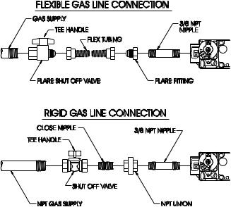
The use of the following gas connectors is recommended:
—ANSZ21.24ApplianceConnectorsofCorrugatedMetalTubing and Fittings
—ANS Z21.45 Assembled Flexible Appliance Connectors of Other Than All-Metal Construction
The above connectors may be used if acceptable by the authority havingjurisdictionThestateofMassachusettsrequiresthataflexible appliance connector cannot exceed three feet in length.
Figure 1
Pressure Testing of the Gas Supply System
1.Tochecktheinletpressuretothegasvalve,a1/8"(3mm)N.P.T. plugged tapping, accessible for test gauge connection, must be placed immediately upstream of the gas supply connection to the appliance.
2.The appliance and its individual shutoff valve must be disconnected from the gas supply piping system during any pressure testing of that system at test pressures in excess of 1/2 psig (3.5 kPa).
3.The appliance must be isolated from the gas supply piping system by closing its individual manual shutoff valve during any pressure testing of the gas supply piping system at test pressures equal to or less than 1/2 psig (3.5 kPa).
Attention! If one of the above procedures results in pressures in excess of 1/2 psig (14" w.c.) (3.5 kPa) on the appliance gas valve, it will result in a hazardous condition.
Checking Manifold Pressure
Natural gas will have a manifold pressure of approximately 3.5" w.c. (.871kPa) for maximum input or 1.7" w.c. (.423kPa) for minimum input at the pressure regulator outlet with the inlet pressure to the pressure regulator from a minimum of 5.0" w.c. (1.245kPa) for the purpose of input adjustment to a maximum of 10.5" w.c. (2.614kPa). Propane gas will have a manifold pressure approximately 10.0"w.c. (2.49kPa) for maximum input or 6.3"w. c. (1.568kPa) for minimum input at the pressure regulator outlet with the inlet pressure to the pressure regulator from a minimum of 11.0"w.c. (2.739kPa) for the purpose of input adjustment to a maximum of 13.0"w.c. (3.237kPa).
NOTE: The gas control is equipped with a captured screw type pressure test point, therefore it is not necessary to provide a 1/8" test point up stream of the control.
Atestgaugeconnectionislocateddownstreamofthegasappliance pressure regulator for measuring gas pressure. The connection is a 1/8 inch 3mm) N.P.T. plugged tapping.
16938-3-0806 |
Page 7 |
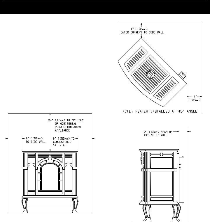
CLEARANCES
Clearances (Figures 2, 3 and 4)
When facing the front of the appliance the following minimum clearances to combustible construction must be maintained.
Top of appliance (ceiling) |
24 |
inches |
Rear Wall |
2 |
inches |
Side Wall |
6 |
inches |
Heater Corners (45° angle) to Wall |
4 |
inches |
Floor |
0 |
inches |
Provide adequate clearances around air openings.
Adequate accessibility clearances for purposes of servicing and proper operation must be provided.
Installation on Rugs and Tile
If this appliance is to be installed directly on carpeting, tile, or other combustible material, other than wood flooring, the appliance shall be installed on a metal or wood panel extending the full width and depth of the appliance.
The base referred to above does not mean the fire-proof base as usedonwoodstoves.Theprotectionisprimarilyforrugsthatmay be extremely thick and light-color tile that can discolor.
Figure 3
Figure 2
Figure 4
Page 8 |
16938-3-0806 |
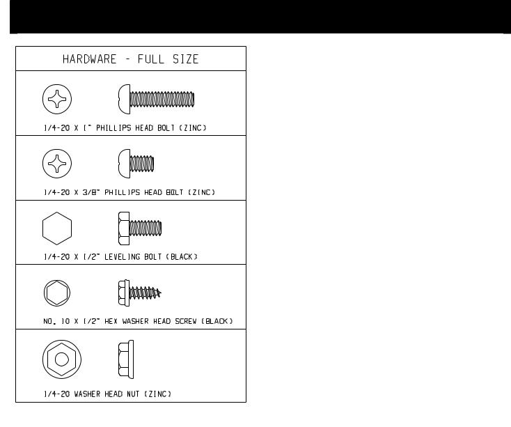
APPLIANCE HARDWARE PACKAGE
Appliance Hardware Package Parts List
Part Description |
Part |
Quantity |
|
Number |
Supplied |
1/4-20 x 1" Phillips Head Bolt |
R-3188 |
4 |
1/4-20 x 3/8" Phillips Head Bolt |
R-3646 |
16 |
1/4-20 x 1/2" Leveling Bolt |
R-3747 |
4 |
No. 10 x 1/2" Hex Washer Head |
R-2737 |
10 |
Screw |
|
|
1/4-20 Washer Head Nut |
R-3185 |
4 |
Leg Pad "A" (see Figure 6) |
CI-008 |
2 |
Leg Pad "B" (see Figure 6) |
CI-009 |
2 |
1-1/4" x 1/2" Retaining Tab (see |
CI-007 |
4 |
Figure 8) |
|
|
1/4" x 9/32 Washer (Not Shown) |
R-1150 |
8 |
Figure 5
16938-3-0806 |
Page 9 |
 Loading...