


INSTALLATION INSTRUCTIONS
AND
OWNER'S MANUAL
CAST IRON
DIRECT VENT FIREPLACE
MODEL
CIDV-30-7
EFFECTIVE DATE
AUGUST, 2000
This appliance may be installed in an aftermarket permanently located, manufactured (mobile) home, where not prohibited by local codes.
This appliance is only for use with the type of gas indicated on the rating plate. This appliance is not convertible for use with other gases, unless a certified kit is used.
WARNING: If the information in this manual is not followed exactly, a fire or explosion may result causing property damage, personal injury or loss of life.
FOR YOUR SAFETY: What to do if you smell gas:
•Do not touch any electrical switches
•Do not try to light any appliance.
•Do not use the phone in your building.
•Immediately call your gas supplier from a neighbor's phone.
•Follow the gas supplier's instructions.
•If you cannot reach your gas supplier, call the fire department.
WARNING: Improper installation, adjustment, alteration, service or maintenance can cause injury or property damage. Refer to this manual. For assistance or additional information consult a qualified installer, service agency, or the gas supplier.
Cet appareil peut être installé dans une maison préfabriquée (mobile) déjà installée à demeure si les règlements locaux le permettent.
Cet appareil doit être utilisé uniquement avec les types de gaz indiqués sur la plaque signalétique. Ne pas l'utiliser avec d'autres gaz sauf si un kit de conversion certifié est installé.
AVERTISSEMENT: Quiconque ne respecte pas à la lettre les instructions dans le présent manuel risque de déclencher un incendie ou une explosion entraíant des dommages matériels, des lésions corporelles ou la perte de vies humaines.
POUR VOTRE SÉCURITÉ: Que faire si vous sentez une odeur de gaz:
•Ne pas tenter d'allumer d'appareil.
•Ne touchez à aucun interrupteur. Ne pas vous servir des téléphones se trouvant dans le bâtiment où vous vous trouvez.
•Évacuez la pièce, le bâtiment ou la zone.
•Appelez immédiatement votre fournisseur de gaz depuis un voisin. Suivez les instructions du fournisseur.
•Si vous ne pouvez rejoindre le fournisseur de gaz, appelez le service dos incendies.
AVERTISSEMENT: Une installation, un réglage, une modification, un entretien ou une maintenance incorrects peuvent entraîner des dommages matériels, des lésions corporelles ou la perte de vies humaines. Consulter le manuel des usagers fourn avec ce générateur d'air chaud.
R-5086 |
Page 1 |

Instructions to Installer
1.Installer must leave instruction manual with owner after installation.
2.Installer must have owner fill out and mail warranty card supplied with appliance.
3.Installer should show owner how to start and operate appliance and thermostat.
WARNING: Any change to this appliance or its control can be dangerous. This is a heating appliance and any panel, door or guard removed for servicing an appliance must be replaced prior to operating the appliance.
General Information
This appliance is design certified in accordance with American National Standard/CSA Standard ANSI Z21.88-1998/CSA 2.33-M98 by the American Gas Association and Canadian Gas Association as a Direct Vent Fireplace and should be installed according to these instructions.
The efficiency rating of this appliance is a product thermal efficiency rating determined under continuous operating conditions and was determined independently of any installed system.
Any alteration of the original design, installed other than as shown in these instructions or use with a type of gas not shown on the rating plate is the responsibility of the person and company making the change.
Notice During initial firing of this unit, its paint will bake out and smoke will occur. To prevent triggering of smoke alarms, ventilate the room in which the unit is installed.
WARNING: Do not operate appliance with the glass front removed, cracked or broken. Replacement of the glass should be done by a licensed or qualified service person.
WARNING: If not installed, operated and maintained in accordance with the manufacturer's instructions, this product could expose you to substances in fuel or from fuel combustion which can cause death or serious illness.
Appliance must not be connected to a chimney flue that is servicing a separate solid-fuel burning appliance.
Attention: All vent runs must have a minimum VERTICAL rise of two feet. If the vent run is directly behind the appliance, you must attach Simpson Dura-Vent 36" snorkel, part number SD-981 on the exterior of the building. See Venting Requirements, page 11.
Specifications
|
Model |
|
|
CIDV-30 |
|
Input BTU/HR (KW/H) Max (LP/NAT) |
|
30,000 (8.7) |
|
|
BTU/HR (KW/H) Min. LP |
|
22,000 (6.4) |
|
|
BTU/HR (KW/H) Min. Nat. |
|
19,500 (5.7) |
|
|
Height |
|
|
27 3/4" (70.5cm) |
|
Width |
|
|
25 1/2" (64.8cm) |
|
Depth |
|
|
23" (58.4cm) |
|
Gas Inlet (Pipe) |
|
1/2" (13mm) |
|
|
Floor to top of collar on vertical |
|
27 5/8" (70.2cm) |
|
|
position of |
Vent Elbow |
|
|
|
Floor to center of collar on horizontal |
|
24 3/32" (61.2cm) |
|
|
position of |
Vent Elbow |
|
|
|
Floor to Center of 90° elbow with a |
|
55 1/2" (141cm) |
|
|
24" length of pipe (see Figure 5) |
|
|
|
|
|
|
|
|
|
Stove Casting (Must be ordered with Firebox.) |
|||
|
CIFB-1 |
Flat Black |
|
|
|
CIPB-1 |
Porcelain Black |
|
|
|
CIPG-1 |
Porcelain Green |
|
|
|
CIPS-1 |
Porcelain Sand |
|
|
|
CIPN-1 |
Porcelain Navy |
|
|
|
CIPR-1 |
Porcelain Red |
|
|
|
Accessories |
|
|
|
|
GWSG-T |
750 Millivolt Wall Thermostat |
|
|
|
DVKH-1 |
Direct Vent Kit for Horizontal Run |
||
|
|
(Includes DVKA-1 Adapter) |
|
|
|
DVKV-1 |
Direct Vent Kit for Vertical Run |
||
|
|
(Includes DVKA-1 Adapter) |
|
|
|
DVKA-1 |
Direct Vent Kit Adapter |
|
|
|
FRBC-1 |
Battery Operated Remote Control |
||
|
FRBTC-1 |
Battery Operated Remote Control w/Thermostat |
||
|
FREC-1 |
Electric Remote Control |
|
|
|
FWS-1 |
Wall Switch |
|
|
|
CIB-2 |
Automatic Blower |
|
|
|
Stone Inlay Replaces Standard Grille Top |
|
||
|
CII-2 |
Stone Inlay |
Empress Green |
|
|
CII-3 |
Stone Inlay |
Hunan Jade |
|
|
CII-4 |
Stone Inlay |
Gray Botticino |
|
|
CII-5 |
Stone Inlay |
Azul |
|
|
CII-6 |
Stone Inlay |
Salome |
|
|
CII-7 |
Stone Inlay |
Black Swan |
|
THIS IS A HEATING APPLIANCE
• Due to high temperatures the appliance should be located out |
• S'assurer que le brû leur et le compartiment des commandes sont |
||
|
of traffic and away from furniture and draperies. |
|
propres. Voir les instructions d'installation et d'utilisation qui |
• |
Children and adults should be alerted to the hazards of high |
|
accompagnent l'appareil. |
|
surface temperatures and should stay away to avoid burns or |
• DO NOT put anything around the furnace that will obstruct |
|
|
clothing ignition. |
|
the flow of combustion and ventilation air. |
• Young children should be carefully supervised when they are |
• DO keep the appliance area clear and free from combustible |
||
|
in the same room as the appliance. |
|
material, gasoline and other flammable vapors and liquids. |
• Clothing or other flammable material should not be placed on |
• |
DO examine venting system periodically and replace dam- |
|
|
or near the appliance. |
|
aged parts. |
• Surveiller les enfants. Garder les vêtements, les meubles, l'essence |
• |
CAUTION: The glass used in your heater is a special high |
|
|
ou autres liquides à vapeur inflammables lin de l'appareil. |
|
temperature ceramic glass. If the glass is cracked or damaged in |
• Any safety screen or guard removed for servicing an appliance |
|
any way, it should be replaced only with a complete glass frame |
|
|
must be replaced prior to operating the appliance. |
|
assembly from Empire. See parts list on Page 26 for ordering. |
• The glass front or any part removed for servicing the appliance |
• |
DO make a periodic visual check of pilot and burner. Clean |
|
|
must be replaced prior to operating the appliance. Work should |
|
and replace damaged parts. |
|
be done by a qualified service person |
• DO NOT use this appliance if any part has been under water. |
|
• |
Keep burner and control compartment clean. |
|
Immediately call a qualified service technician to inspect the |
• |
Vent cap hot while furnace is in operation. |
|
appliance and to replace any part of the control system and |
• Installation and repair should be done by a QUALIFIED |
|
any gas control which has been under water. |
|
|
SERVICE PERSON. The appliance should be inspected be- |
• |
Ne pas se servir de cet appareil s'il a été plongé dans l'eau, |
|
fore use and at least annually by a qualified service person. |
|
complètement ou en partie. Appeler un technicien qualifié pour |
|
More frequent cleaning may be required due to excessive lint |
|
inspecter l'appareil et remplacer toute partie du système de |
|
from carpeting, bedding materials, etc. It is imperative that |
|
contrôle et toute commande qui ont été plongés dans l'eau. |
|
control compartments, burners and circulating air passage- |
• Under no circumstances should any solid fuels (wood, coal, paper |
|
|
ways of the appliance be kept clean. |
|
or cardboard, etc.) be used in this appliance. |
|
|
|
|
Page 2 |
R-5086 |

SAFETY INFORMATION FOR USERS OF LP-GAS
Propane (LP-Gas) is a flammable gas which can cause fires and explosions. In its natural state, propane is odorless and colorless. You may not know all the following safety precautions which can protect both you and your family from an accident. Read them carefully now, then review them point
by point with the members of your household. Someday when there may not be a minute to lose, everyone's safety will depend on knowing exactly what to do. If, after reading the following information, you feel you still need more information, please contact your gas supplier.
LP-GAS WARNING ODOR
If a gas leak happens, you should be able to smell the gas because of the odorant put in the LP-Gas. That's your signal to go into immediate action!
•Do not operate electric switches, light matches, use your phone. Do not do anything that could ignite the gas.
•Get everyone out of the building, vehicle, trailer, or area. Do that IMMEDIATELY.
•Close all gas tank or cylinder supply valves.
•LP-Gas is heavier than air and may settle in low areas such as basements. When you have reason to suspect a gas leak, keep out of basements and other low areas. Stay out until
firefighters declare them to be safe.
•Use your neighbor's phone and call a trained LP-Gas service person and the fire department. Even though you may not continue to smell gas, do not turn on the gas again. Do not re-enter the building, vehicle, trailer, or area.
•Finally, let the service man and firefighters check for escaped gas. Have them air out the area before you return. Properly trained LP-Gas service people should repair the leak, then check and relight the gas appliance for you.
NO ODOR DETECTED - ODOR FADE
Some people cannot smell well. Some people cannot smell the odor of the chemical stench put into the gas. You must find out if you can smell the odorant in propane. Smoking can decrease your ability to smell. Being around an odor for a time can affect your sensitivity or ability to detect that odor. Sometimes other odors in the area mask the gas odor. People may not smell the gas odor or their minds are on something else. Thinking about smelling a gas odor can make it easier to smell.
The odorant in LP-gas is colorless, and it can fade under some circumstances. For example, if there is an underground leak, the movement of the gas through soil can filter the odorant. Odorants in LP-Gas also are subject to oxidation. This fading
can occur if there is rust inside the storage tank or in iron gas pipes.
The odorant in escaped gas can adsorb or absorb onto or into walls, masonry and other materials and fabrics in a room. That will take some of the odorant out of the gas, reducing its odor intensity.
LP-Gas may stratify in a closed area, and the odor intensity could vary at different levels. Since it is heavier than air, there may be more odor at lower levels. Always be sensitive to the slightest gas odor. If you detect any odor, treat it as a serious leak. Immediately go into action as instructed earlier.
SOME POINTS TO REMEMBER
•Learn to recognize the odor of LP-gas. Your local LP-Gas Dealer can give you a "Scratch and Sniff" pamphlet. Use it to find out what the propane odor smells like. If you suspect that your LP-Gas has a weak or abnormal odor, call your LPGas Dealer.
•If you are not qualified, do not light pilot lights, perform service, or make adjustments to appliances on the LP-Gas system. If you are qualified, consciously think about the odor of LP-Gas prior to and while lighting pilot lights or performing service or making adjustments.
•Sometimes a basement or a closed-up house has a musty smell that can cover up the LP-Gas odor. Do not try to light pilot lights, perform service, or make adjustments in an area where the conditions are such that you may not detect the odor if there has been a leak of LP-Gas.
•Odor fade, due to oxidation by rust or adsorption on walls of new cylinders and tanks, is possible. Therefore, people should be particularly alert and careful when new tanks or cylinders are placed in service. Odor fade can occur in new tanks, or reinstalled old tanks, if they are filled and allowed
to set too long before refilling. Cylinders and tanks which have been out of service for a time may develop internal rust which will cause odor fade. If such conditions are suspected to exist, a periodic sniff test of the gas is advisable. If you have any question about the gas odor, call your LP-gas dealer. A periodic sniff test of the LP-gas is a good safety measure under any condition.
•If, at any time, you do not smell the LP-Gas odorant and you think you should, assume you have a leak. Then take the same immediate action recommended above for the occasion when you do detect the odorized LP-Gas.
•If you experience a complete "gas out," (the container is under no vapor pressure), turn the tank valve off immediately. If the container valve is left on, the container may draw in some air through openings such as pilot light orifices. If this occurs, some new internal rusting could occur. If the valve is left open, then treat the container as a new tank. Always be sure your container is under vapor pressure by turning it off at the container before it goes completely empty or having it refilled before it is completely empty.
R-5086 |
Page 3 |

Installation in Residential Garages
Gas utilization equipment in residential garages shall be installed so that all burners and burner ignition devices are located not less than 18" (457mm) above the floor.
Such equipment shall be located, or protected, so it is not subject to physical damage by a moving vehicle.
Qualified Installing Agency
Installation and replacement of gas piping, gas utilization equipment or accessories and repair and servicing of equipment shall be performed only by a qualified agency. The term "qualified agency" means any individual, firm, corporation or company which either in person or through a representative is engaged in and is responsible for (a) the installation or replacement of gas piping or (b) the connection, installation, repair or servicing of equipment, who is experienced in such work, familiar with all precautions required and has complied with all the requirements of the authority having jurisdiction.
The installation must conform with local codes, or, in the absence of local codes, with the National Fuel Gas Code, ANSI Z223.1*/Canadian
Installation Code, CAN/CGA B149.
*Available from the American National Standards Institute, Inc., 11 West 42nd St., New York,
NY 10036.
Installer l'appareil selon les codes ou règlements locaux, ou, en l'absence de tels règlements, selon les Codes d'installation CAN/CGA-B149.
Introduction
This model is a direct vent gas appliance and is designed to operate with all combustion air being siphoned from the outside of the building and all exhaust gases expelled to the outside of the building.
Warning: This unit is not for use with solid fuel.
Pre-Installation Preparation
This direct vent gas fireplace and its components are tested and safe when installed in accordance with this Installation Manual. Report to your dealer any parts damaged in shipment, specifically check glass condition. Do not install unit with damaged, incomplete, or substitute parts. Read all instructions before starting installation and follow these instructions carefully during installation to insure maximum benefit and safety. Failure to follow them will void your warranty and may present a fire hazard.
The Empire Comfort System, Inc. warranty will be voided by, and Empire Comfort System, Inc. disclaims any responsibility for the following actions:
•Installation of any damaged fireplace or vent system component.
•Modification of the fireplace or direct vent system.
•Installation other than as instructed by Empire Comfort System, Inc.
•Improper positioning of the gas logs or the glass door.
•Installation and/or use of any component part not manufactured or approved by Empire Comfort System, Inc.
High Altitude Installation
When installing this unit at an elevation above 2000 feet (in the United States) it may be necessary to decrease the input rating by changing the existing burner orifice to a smaller size. Generally, input should be reduced 4 percent for each 1000 feet above sea level. However, if the heating value of the gas has been reduced, this general rule may not apply. Check with local gas utility for proper orifice size identification.
APPLIES TO CANADIAN MODELS ONLY
Altitude: 0-4,500 feet (0-1370 m) without orifice change.
For high altitude installations consult the local gas distributor or the authority having jurisdiction for proper rating methods. If the installer must convert the unit to adjust for varying altitudes, the information sticker (illustrated below) must be filled out by the installer and adhered to the appliance at the time of conversion.
THE CONVERSION SHALL BE CARRIED OUT BY A MANUFACTURER'S AUTHORIZED REPRESENTATIVE IN ACCORDANCE WITH THE REQUIREMENTS OF THE MANUFAC-
Page 4
TURER, PROVINCIAL OR TERRITORIAL AUTHORITIES HAVING JURISDICTION AND IN ACCORDANCE WITH THE REQUIREMENTS OF THE CAN/CGA-B141.1 OR CAN/CGA-B141.2 INSTALLATION CODES.
LA CONVERSION DOIT ÊTRE EFFECTUÉE CONFORMÉMENT AUX RÉGLEMENTATION PROVINCIAUX EN CAUSE ET AUX EXIGENCES DES CODES D'INSTALLATION CAN/CGA-B149.
This appliance has been converted for use at an altitude of
Orifice size |
|
|
|
Manifold Pressure |
|
||
Input (Btu/h) |
|
|
Fuel Type |
|
|
|
|
Date of Conversion |
|
Converted by |
|
|
|||
Cet appareil a été converti au
Injecteur Pression à la tubulure d'alimentation Déoit calorifique
Gas Supply (Figure 1)
Check all local codes for requirements, especially for the size and type of gas supply line required.
Recommended Gas Pipe Diameter
Pipe Length |
Schedule 40 Pipe |
Tubing, Type L |
||
(Feet) |
Inside Diameter |
Outside Diameter |
||
|
Nat. |
L.P. |
Nat. |
L.P. |
0-10 |
1/2" |
3/8" |
1/2" |
3/8" |
|
1.3 cm |
1.0 cm |
1.3 cm |
1.0 cm |
10-40 |
1/2" |
1/2" |
5/8" |
1/2" |
|
1.3 cm |
1.3 cm |
1.6 cm |
1.3 cm |
|
|
|
|
|
40-100 |
1/2" |
1/2" |
3/4" |
1/2" |
|
1.3 cm |
1.3 cm |
1.9 cm |
1.3 cm |
100-150 |
3/4" |
1/2" |
7/8" |
3/4" |
|
1.9 cm |
1.3 cm |
2.2 cm |
1.9 cm |
|
|
|
|
|
Note: Never use plastic pipe. Check to confirm whether your local codes allow copper tubing or galvanized.
Note: Since some municipalities have additional local codes, it is always best to consult your local authority and installation code.
The use of the following gas connectors is recommended:
—ANS Z21.24 Appliance Connectors of Corrugated Metal Tubing and Fittings
—ANS Z21.45 Assembled Flexible Appliance Connectors of Other Than All-Metal Construction
The above connectors may be used if acceptable by the authority having jurisdiction.
Consult the current National Fuel Gas Code, ANSI Z223.1 CAN/CGAB149 (.1 or .2) installation code.
Installing a New Main Gas Cock
Each appliance should have its own manual gas cock.
A manual main gas cock should be located in the vicinity of the unit. Where none exists, or where its size or location is not adequate, contact your local authorized installer for installation or relocation.
Compounds used on threaded joints of gas piping shall be resistant to the action of liquefied petroleum gases. The gas lines must be checked for leaks by the installer. This should be done with a soap solution watching for bubbles on all exposed connections, and if unexposed, a pressure test should be made.
Never use an exposed flame to check for leaks. Appliance must be disconnected from piping at inlet of control valve and pipe capped or plugged for pressure test. Never pressure test with appliance connected; control valve will sustain damage!
A gas valve and ground joint union should be installed in the gas line upstream of the gas control to aid in servicing. It is required by the National Fuel Gas Code that a drip line be installed near the gas inlet. This should consist of a vertical length of pipe tee connected into the gas line that is capped on the bottom in which condensation and foreign particles
may collect.
R-5086
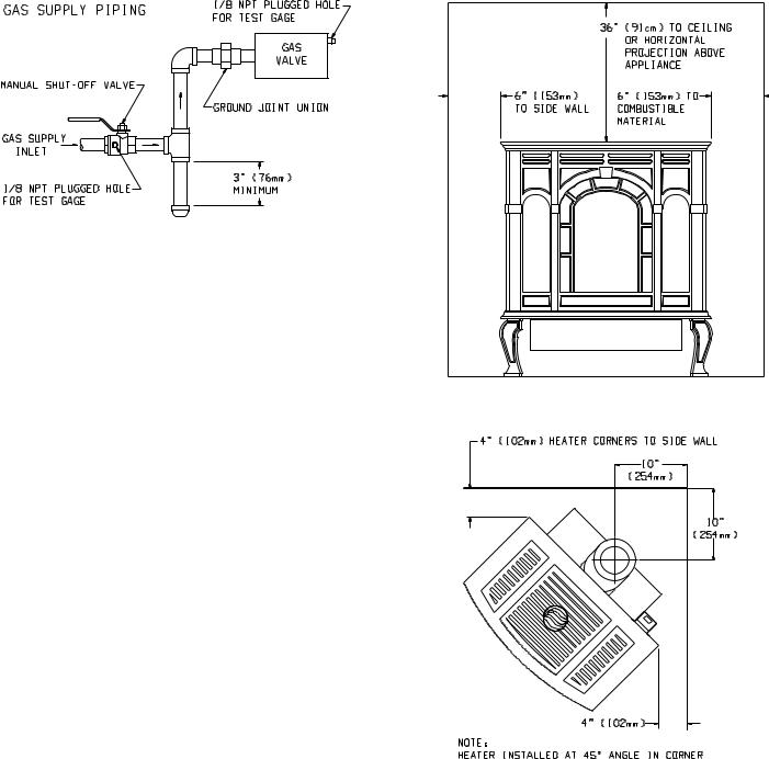
Figure 1
Method of Installing a Tee Fitting Sediment Trap Pressure Testing of the Gas Supply System
1.To check the inlet pressure to the gas valve, a 1/8" (3mm) N.P.T. plugged tapping, accessible for test gauge connection, must be placed immediately upstream of the gas supply connection to the appliance.
2.The appliance and its appliance main gas valve must be disconnected from the gas supply piping system during any pressure testing of that system at test pressures in excess of 1/2 psig (3.5 kPa).
3.The appliance must be isolated from the gas supply piping system by closing its equipment shutoff valve during any pressure testing of the gas supply piping system at test pressures equal to or less than 1/2 psig (3.5 kPa).
Attention! If one of the procedures results in pressures in excess of 1/2 psig (14" w.c.) (3.5 kPa) on the appliance gas valve, it will result in a hazardous condition.
Checking Manifold Pressure
Both Propane and Natural gas valves have a built-in pressure regulator in the gas valve. Natural gas models will have a manifold pressure of approximately 3.5" w.c. (.871kPa) for maximum input or 1.7" w.c. (.423kPa) for minimum input at the valve outlet with the inlet pressure to the valve from a minimum of 5.0" w.c. (1.245kPa) for the purpose of input adjustment to a maximum of 10.5" (2.615kPa) w.c. Propane gas models will have a manifold pressure approximately 10.0"w.c. (2.49kPa) for maximum input or 5.9" w.c. (1.469kPa) for minimum input at the valve outlet with the inlet pressure to the valve from a minimum of 11.0" w.c. (2.739kPa) for the purpose of input adjustment to a maximum of 13.0" w.c. (3.237kPa).
A 1/8" (3mm) N.P.T. plugged tapping, accessible for test gauge connection, is located on the outlet side of the gas control.
Installation on Rugs and Tile
If this appliance is to be installed directly on carpeting, tile, or other combustible material, other than wood flooring, the appliance shall be installed on a metal or wood panel extending the full width and depth of the appliance.
The base referred to above does not mean the fire-proof base as used on wood stoves. The protection is primarily for rugs that may be extremely thick and light-color tile that can discolor.
Clearances (Figures 2, 3, 4 and 5)
In selecting a location for installation, it is necessary to provide adequate accessibility clearances for servicing and proper operation.
Locating and Venting the Direct Vent Fireplace
Clearances: When facing the front of the direct vent fireplace the minimum clearances to combustible construction (material) are the following:
Top of appliance (ceiling) |
36 |
(inches) |
Rear Wall |
2 |
(inches) |
Side Wall |
6 |
(inches) |
Heater Corners (45° angle) to Wall |
4 |
(inches) |
Floor |
0 |
(inches) |
R-5086
Figure 2
Figure 3
Page 5

90°(145524"610mm)PIPEELBOW/2"cm)SECTION
|
Appliance Hardware Package (Figure 6) |
|
||
|
|
Figure 6 |
|
|
|
Appliance Hardware Package Parts List |
|
||
|
Part |
|
Part |
Quantity |
|
Description |
|
Number |
Supplied |
|
1/4-20 x 1" Phillips Head Bolt |
R-3188 |
4 |
|
|
1/4-20 x 3/8" Phillips Head Bolt |
R-3646 |
16 |
|
|
1/4-20 x 1/2" Leveling Bolt |
R-3747 |
4 |
|
|
No. 10 x 1/2" |
R-2737 |
8 |
|
|
Hex Washer Head Screw |
|
|
|
|
1/4-20 Washer Head Nut |
R-3185 |
4 |
|
|
Leg Pad "A" |
(see Figure 7) |
CI-008 |
2 |
|
Leg Pad "B" |
(see Figure 7) |
CI-009 |
2 |
Figure 5 |
1-1/4" x 1/2" Retaining Tab |
CI-007 |
4 |
|
(see Figure 10) |
|
|
||
|
|
|
||
|
1/4 x 9/32 Washer (Not Shown) |
R-1150 |
8 |
|
|
Assembly of Cast Iron (Outer Casing) Stove Casting |
|
||
|
(Figures 7, 8, 9, 10, 11 and 12) |
|
|
|
|
Attention: Included in the hardware package are (8) 1/4" inside diam- |
|||
|
eter washers. A 1/4" washer may be used with a 1/4-20 x 3/8" bolt when |
|||
|
assembling the stove casting parts. If a bolt hole is not tapped deep |
|||
|
enough for a tight fit between stove casting parts, the 1/4" washer can |
|||
|
be used as a shim to provide a tight fit. |
|
|
|
|
The 1/4" washers are not required for assembly of the stove casting if all |
|||
|
the bolt holes are tapped to a proper depth. |
|
|
|
|
Additonal 1/4" washers are to be purchased locally. |
|
||
|
1. Place porcelain casting pieces on a non-abrasive surface in order |
|||
Page 6 |
|
|
|
R-5086 |
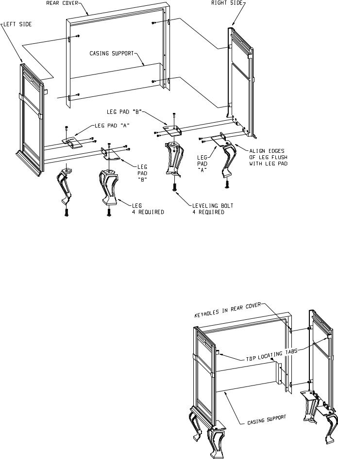
Figure 7
to protect the porcelain finish. The exterior of the porcelain casting pieces should be facing the non-abrasive surface.
2.The assembly of the casting is accomplished in 6 stages:
A.Attaching legs to the sides (Figure 7).
B.Attaching rear cover to sides (Figure 8).
C.Removing protective packaging from casing front and window (Figure 9).
D.Assembly of front by attaching retaining tabs and placing front on unit (Figure 10).
E.Inserting firebox into partially completed assembly (Figure 11 and Figure 12).
F.Placing top on unit.
Detailed Instructions Follow
3.Refer to Figure 7, the leg pads will have the letter "A" and "B" stamped into the metal. Place leg pad "A" and leg pad "B" at the bottom of each casing side. Leg pad "A" attaches to the front of the casing side, right and to the rear of the casing side, left. Leg pad "B" attaches to the rear of the casing side, right and to the front of the casing side, left. Position the 3/4" flange on the leg pad against the
(2)locator dimples on the casing side. The 3/4" flange must be facing upward, toward the top louver openings on the casing side. Attach the two rear leg pads to the casing sides with (2) 3/8" bolts. Attach but do not completely tighten the two front leg pads to the casing sides with (2) 3/8" bolts. Attention: The front leg pads can be adjusted to provide a snug fit between the casing front and the casing sides.
4.Attach (4) leveling bolts to the bottom of the (4) legs.
5.Align the 3/8" hole at the top of the leg with the 3/8" hole in the leg pad. Attention: For proper positioning of the leg to the leg pad the
(2)1-1/2" top edges of the leg must be placed flush and parallel to the (2) edges on the leg pad. Attach leg to leg pad by inserting (1) 1" bolt through the leg pad and into the leg, secure bolt with 1/4" nut.
6.Insert (2) 3/8" bolts into the (2) holes on the edges of the casing sides. The bolts should only be threaded half-way into the holes in order to allow for clearance when the casing back is attached to the casing sides.
R-5086
7.Refer to Figure 8, attach casing support to rear cover with (4) 10 x 1/2" screws. The rear cover has (4) keyholes for attachment to the casing sides. Stand the casing sides on the floor with the (2) bolts attached halfway into the edges of the rear cover positioned at the rear. The large diameter holes in the keyholes of the rear cover will be toward the floor. Working with one casing side at a time, place the large diameter holes in the keyholes over and behind both of the bolts at the same time. Push downward on the rear cover to lock the keyholes into position behind the bolts. Finish tightening both bolts to secure rear cover to casing side. Repeat this procedure to secure rear cover to the second casing side.
Figure 8
Page 7

8.Position the completed portion of the casing in the approximate location for installation as the completed assembly will be heavy.
9.Refer to Figure 9, removing protective packing foam from casing front and window. Remove the (1) 3/4" bolt and (1) 1/4" washer from top of window. Remove (1) 3/8" bolt and 1 - 5/8" x 3/4" retaining tab from bottom of window. Remove the window from casing front. Remove the protective sheet of foam from the casing front.
Place the window into the casing front. Attach the top of the window to the casing front with (1) 1/4" washer and (1) 3/4" bolt. Place the 1 -5/8" x 3/4" retaining tab into the locator notch on the bottom of the casing front. Attach the bottom of the window to the casing front by inserting (1) 3/8" bolt through retaining tab and into locator notch.
10.Attach the (4) 1-1/4" x 1/2" retaining tabs to the casing front with
(4)3/8" bolts. The retaining tabs should be positioned downward.
11.Refer to Figure 10, attach casing front to outer casing by using the
(4)retaining tabs on the casing front. The (2) top, retaining tabs on the casing front will be placed behind the (2) top, locator tabs on the front of the casing sides. The (2) bottom, retaining tabs will be inserted into the (2) 9/16" slots on the front, leg pads. Place the top, retaining tabs behind the top, locator tabs as you pivot inward the bottom of the casing front in order to insert the bottom, retaining tabs into the slots.
Page 8
Figure 10
12.The following procedure will provide a snug fit between the casing front and the casing sides. Grasp the right, front leg, push inward on the leg in order to provide a snug fit between the casing front and the casing side. Continue to hold the right, front leg as you completely tighten the (2) 3/8" bolts that attach the leg pad to the right, casing side. Repeat procedure for left, front leg to achieve a snug fit between the casing front and the casing side.
13.Remove the casing front from the outer casing.
14.Refer to Figures 11 and 12, the appliance firebox can now be inserted into the outer casing. Center the firebox in the outer casing. Attention: Remove (1) Phillips-head screw in the top of the valve cover. The screw is used to secure the valve cover in place during shipping. The (1) Phillips-head screw can be discarded.
R-5086
Figure 9

15.Attach casing front to outer casing as described in Step 11.
16.Place the casing top onto the outer casing. The casing top nests into the outer casing.
17.Insert center grille, left grille and right grille into casing top.
Figure 11
F 13
R-5086 |
Page 9 |
 Loading...