


VSS/VSR/VSM single screw compressor
Operation and service manual
Important Message
READ CAREFULLY BEFORE INSTALLING AND STARTING YOUR COMPRESSOR.
The following instructions have been prepared to assist in installation, operation and removal of Vilter™ Single Screw Compressors. Following these instructions will result in a long life of the compressor with satisfactory operation.
The entire manual should be reviewed before attempting to install, operate, service or repair the compressor.
A compressor is a positive displacement machine. It is designed to compress gas. The compressor must not be subjected to liquid carry over. Care must be exercised in properly designing and maintaining the system to prevent conditions that could lead to liquid carry over. Vilter Manufacturing is not responsible for the system or the controls needed to prevent liquid carry over and as such Vilter Manufacturing cannot warrant equipment damaged by improperly protected or operating systems.
Vilterscrewcompressorcomponentsarethoroughlyinspectedatthefactory. However,damagecanoccur in shipment. For this reason, the equipment should be thoroughly inspected upon arrival. Any damage noted should be reported immediately to the Transportation Company. This way, an authorized agent can examine the unit, determine the extent of damage and take necessary steps to rectify the claim with no serious or costly delays. At the same time, the local Vilter representative or the home office should be notified of any claim made.
All inquires should include the Vilter sales order number, compressor serial and model number. These can be found on the compressor name plate on the compressor.
All requests for information, services or parts should be directed to:
Vilter Manufacturing LLC
Customer Service Department
P.O. Box 8904
5555 South Packard Ave
Cudahy, WI 53110-8904 USA Telephone: 1-414-744-0111 Fax:1-414-744-3483
e-mail: info.vilter@emerson.com
Equipment Identification Numbers:
Vilter Order Number: _______________________Compressor Serial Number: _________________
Vilter Order Number: _______________________Compressor Serial Number: _________________
Vilter Order Number: _______________________Compressor Serial Number: _________________
Vilter Order Number: _______________________Compressor Serial Number: _________________
3
4

Table of Contents
Important Message .............................................................................................................. |
3 |
Standard VILTER Warranty Statement .................................................................................. |
6 |
Standard VILTER 5/15 Warranty Statement .......................................................................... |
7 |
Long Term Storage Requirements ......................................................................................... |
8 |
Description......................................................................................................................... |
10 |
Foundation......................................................................................................................... |
12 |
Rigging and Lifting ............................................................................................................. |
19 |
Installation ......................................................................................................................... |
23 |
Slide Valve Actuator Installation & Calibration ............................................................... |
35 |
Slide Valve Operation .................................................................................................... |
38 |
Slide Valve Actuator Trouble Shooting Guide ................................................................. |
39 |
Operation Section .............................................................................................................. |
43 |
Notice on using Non-Vilter Oils...................................................................................... |
43 |
Operation ..................................................................................................................... |
44 |
Pre Start-Up Checklists .................................................................................................. |
52 |
Field Piping and Mechanical Requirements .................................................................... |
53 |
Field Wiring Requirements ............................................................................................ |
54 |
Stop Check Valve Operation .......................................................................................... |
55 |
Service .......................................................................................................................... |
56 |
Maintenance ................................................................................................................. |
87 |
VSS Parts Section................................................................................................................ |
88 |
Gate Rotor..................................................................................................................... |
89 |
Shaft Seal ...................................................................................................................... |
93 |
Main Rotor .................................................................................................................... |
94 |
Slide Valve Cross Shafts and End Plate............................................................................ |
96 |
Slide Valve Carriage Assembly ....................................................................................... |
98 |
Actuator & Command Shaft......................................................................................... |
102 |
Miscellaneous Frame Components .............................................................................. |
104 |
Replacement Tools ...................................................................................................... |
108 |
VSM 301-701 Replacement Parts Section.......................................................................... |
111 |
Gaterotor Assembly .................................................................................................... |
112 |
Shaft Seal .................................................................................................................... |
115 |
Main Rotor, Slide Valve Cross Shafts & End Plate .......................................................... |
116 |
Slide Valve Carriage Assembly ..................................................................................... |
120 |
Actuator & Command Shaft......................................................................................... |
122 |
Miscellaneous Frame Components .............................................................................. |
124 |
Replacement Tools ...................................................................................................... |
128 |
Danfoss Liquid Injection Valve Setup................................................................................. |
129 |
Appendix A: Pre Start Up for Remote Oil Coolers ............................................................... |
143 |
5

Standard VILTER Warranty Statement
Seller warrants the products it manufactures to be free from defects in material and workmanship for a period of eighteen (18) months from the date of shipment from Seller’s manufacturing plant or twelve (12) months from date of installation at the initial end users location, whichever occurs first. In addition, Seller provides the following extended warranties: (a) three (3) years from the date of shipment on single screw compressor internal rotating parts, (b) two (2) years from the date of shipment on reciprocating compressors and single screw and reciprocating compressor parts, and (c) two (2) years on all other parts on a single screw compressor unit. Such warranties do not apply to ordinary wear and tear. Seller does not warrant that the product complies with any particular law or regulation not explicitly set forth in the specifications, and Buyer is responsible for ensuring that the product contains all features necessary to safely perform in Buyer’s and its customer’s plants and operations. Buyer must notify Seller of any warranty claim within ten (10) days after such claim arises, otherwise Buyer waives all rights to such claim. Products supplied by Seller, which are manufactured by others, are not warranted by Seller, but rather Seller merely passes through the manufacturer’s warranty to Buyer.
SELLER EXPRESSLY DISCLAIMS ALL OTHER WARRANTIES, WHETHER EXPRESS OR IMPLIED, INCLUDING THE IMPLIED WARRANTIES OF MERCHANTABILITY AND FITNESS FOR A PARTICULAR PURPOSE.
Unless otherwise agreed in writing, Buyer’s sole remedy for breach of warranty is, at Seller’s option, the repair of the defect, the correction of the service, or the providing a replacement part FOB Seller’s office. Seller will not be responsible for costs of dismantling, lost refrigerant, reassembling, or transporting the product. Further, Seller will not be liable for any other direct, indirect, consequential, incidental, or special damages arising out of a breach of warranty. THESE WARRANTY REMEDIES ARE EXCLUSIVE AND ALL OTHER WARRANTY REMEDIES ARE EXCLUDED.
Products or parts for which a warranty claim is made are to be returned transportation prepaid to Seller’s factory. Any improper use, corrosion, neglect, accident, operation beyond rated capacity, substitution of parts not approved by Seller, or any alteration or repair by others which, in Seller’s judgement, adversely affects the Product, shall void all warranties and warranty obligations. Further, Seller shall not be liable under the above warranties should Buyer be in default of its payment obligations to Seller under this Agreement or any credit agreement.
6

Standard VILTER 5/15 Warranty Statement
The seller extends warranty, from date of shipment, to a period of fifteen (15) years on all compressor bearings, five (5) years on all internal compressor parts and two (2) years on the remainder of the parts on single screw compressor units. If within such period any such product shall be proved to Seller’s satisfaction to be defective, such product shall be repaired or replaced at Seller’s option. Such repair or replacement shall be Seller’s sole obligation and Buyer’s exclusive remedy hereunder and shall be conditioned upon Seller’s receiving written notice of any alleged defect within ten (10) days after its discovery and, at Seller’s option, return of such parts to Seller, F.O.B., freight prepaid to Seller’s factory. Expenses incurred by Buyer in repairing or replacing any defective product or any lost refrigerant will not be allowed except by written permission of Seller. This warranty is only applicable to products properly maintained and used according to Seller’s instructions, the use of genuine Vilter replacement parts and recommended oil in all repairs and replacements has demonstrated adherence to a scheduled maintenance program as detailed in the Single Screw Compressor operating manual. This warranty does not apply to normal wear and tear, or damage caused by corrosion, misuse, overloading, neglect, improper operation, accident or alteration, as determined by Seller. Products supplied by seller hereunder, which are manufactured by someone else, are not warranted by Seller in any way, but Seller agrees to assign to Buyer any warranty rights in such products that the Seller may have from the original manufacturer. Labor and expenses for repair are not covered by warranty.
THE WARRANTY CONTAINED IN THIS SECTION IS EXCLUSIVE AND IN LIEU OF ALL OTHER REPRESENTATIONS AND WARRANTIES (EXCEPT OF TITLE), EXPRESS OR IMPLIED WARRANTY OF MERCHANTABILITY OR IMPLIED WARRANTY OF FITNESS FOR A PARTICULAR PURPOSE.
Any description of the product, whether in writing or made orally by Seller or Seller’s agents, specifications, samples, models, bulletins, drawings, diagrams, engineering sheets or similar materials used in connection with Buyer’s order are for the sole purpose of identifying the products and shall not be construed as an express warranty. Any suggestions by seller or Seller’s agents regarding use, application or suitability of the products shall not be construed as an express warranty unless confirmed to be such in writing by Seller. The 5/15 Extended Warranty shall be applicable only if the specific maintenance guidelines as outlined in the technical manual are followed. This includes the compressor inspections, completing periodic oil analysis and the change out of the oil and oil filters, and related components as required with only genuine Vilter parts. The customer is required to keep a maintenance log and receipts demonstrating the use of Genuine Vilter parts for validation of a warranty claim, if requested.
Note: The 5/15 warranty applies to NEW compressors only, and does NOT include used or remanufactured compressors.
7

Long Term Storage Requirements
The procedure described is a general recommendation for long term storage (over one month of no operation) of Vilter Manufacturing packages and compressors. While this procedure is intended to cover most of the commonly encountered situations, it is the responsibility of the installation firm and end user to address any unusual conditions. We suggest using the accompanying Long Term Storage Log sheet for recording purposes to validate the appropriate procedures.
Prior to start-up, Vilter recommends that a complete system pressure check be performed. Upon verification of the system integrity, a comprehensive evacuation procedure should be completed to ensure a dry system before gas is introduced. The oil circuit of any compressor is to be primed at initial start-up through the prelube oil pump on screw compressors.
Warranty of the system remains in effect as described in Section 5, Product Warranty and Procedures.
*If the unit is designed for indoor duty, it must be stored in a heated building.
If the unit is designed for outdoor duty, and is to be stored outdoors, a canvas tarp is recommended for protection until installation is imminent. Adequate drainage should be provided, by placing wood blocks under the base skid, so that water does not collect inside the base perimeter or low spots in the tarp.
*All compressor stop valves are to be closed to isolate the compressor from the remainder of the system. All other valves, except those venting to atmosphere, are to be open. It is essential that the nitrogen holding charge integrity be maintained.
*Cover all bare metal surfaces (coupling, flange faces, etc.) with rust inhibitor.
*Desiccant is to be installed in the control panel. If the panel is equipped with a space heater, it is to be energized. If the panel does not have a space heater, use a thermostatically controlled 50-watt light bulb. Use an approved electrical spray-on corrosion inhibitor for panel components (relays, switches, etc.)
*All pneumatic controllers and valves (Fisher, Taylor, etc.) are to be covered with plastic bags and sealed with desiccant bags inside.
*System and compressor pressures (unit is shipped with dry nitrogen holding charge approximately 5 psi above atmospheric pressure) are to be monitored, on a regular basis, for leakage. It will be necessary to add a gauge to monitor the system holding charge pressure. If a drop in pressure occurs, the source of leakage must be found and corrected. The system must be evacuated and recharged with dry nitrogen to maintain the package integrity.
*Motors – (NOTE: The following are general recommendations. Consult the manufacturer of your motor for specific recommendations.)
1)Remove the condensation drain plugs from those units equipped with them and insert silica-gel into the openings. Insert one-half pound bags of silica-gel (or other desiccant material) into the air inlets and outlets of drip-proof type motors.
NOTE: The bags must remain visible, and tagged, so they will be noticed and removed when the unit is prepared for service.
8

Long Term Storage Requirements
2)Cover the unit completely to exclude dirt, dust, moisture, and other foreign materials.
3)If the motor can be moved, it is suggested that the entire motor be encased in a strong, transparent plastic bag. Before sealing this bag, a moisture indicator should be attached to the side of the motor and several bags of silica-gel desiccant put inside the bag, around the motor. When the moisture indicator shows that the desiccant has lost its effectiveness, as by a change in color, the bag should be opened and fresh replacement desiccants installed.
Whenever the motor cannot be sealed, space heaters must be installed to keep the motor at least 10°F above the ambient temperature.
NOTE: There is a potential for damage by small rodents and other animals that will inhabit motors in search of warm surroundings or food. Due to this, a possibility of motor winding destruction exists. Sealing motor openings should restrict access to the motor.
4) Rotate motor and compressor shafts several revolutions (approximately 6) per month to eliminate flat spots on the bearing surfaces. If the compressor unit is installed, wired and charged with oil, open all oil line valves and run the oil pump for 10 seconds prior to rotating the compressor shaft. Continue running the oil pump while the compressor shaft is being turned to help lubricate the surfaces of the shaft seal.
9

Description
COMPRESSOR
The Vilter Single Screw Compressor is a positive displacement, capacity and volume controlled, oil flooded, rotary compressor which uses a single main screw intermeshed by two opposing gate rotors. Gas compression occurs when the individual fingers of each gate rotor sweep through the grooves, or flutes, of the main screw as the screw rotates. Compression occurs from the time the screw flute is first closed off by the gate rotor finger, until the time when the screw flute has rotated to the point of lining up with the discharge port in the compressor housing. A labyrinth type seal is used to prevent gas at discharge pressure from leaking past the end of the screw. Any discharge gas leakage past the labyrinth seal is vented back to suction via four longitudinal holes drilled through the body of the screw.
By venting the discharge end of the main screw back to suction, forces on each end of the screw are equal. This results in zero net axial forces on the main bearings. With twin opposing gate rotors, all radial forces are cancelled out also. Main shaft bearings have no net forces except the weight of the screw and the shaft assembly.
The compressors are comprised of three rotating assemblies: the main screw assembly and the two gate rotor assemblies. Each of these rotating assemblies use a common bearing configuration consisting of a single, cylindrical rolling element bearing at one end, and a pair of angular contact ball bearings at the other end. The pair of angular contact ball bearings are used to axially fix one end of the rotating shafts, and to absorb the small amount of thrust loads on the shafts. The inner races of the ball bearings are securely clamped to the rotating shafts, while the outer races are securely held in the bearing housing, thus fixing the axial position of the shaft in relation to the bearing housings. The cylindrical roller bearings at the opposite end of the shafts allow for axial growth of the shafts while supporting the radial loads from the shafts.
The suction gas enters the compressor housing through the top inlet flange, at the driven end of the unit. The driven end of the compressor housing is flooded with gas at suction pressure. The gas enters the open end of the main screw flutes at the driven end, and becomes trapped in the screw flute as the screw rotates and the gate rotor tooth enters the end of the flute. At this point, the compression process begins. Directly after the screw flute is closed off by the gate rotor tooth, oil is injected into the groove.
The oil enters the compressor through a connection at the top of the compressor. The purpose of the injected oil is to absorb the heat of compression, to seal the gate rotor tooth in the groove, and to lubricate the moving parts.
Additional internal oiling ports are provided at the main and gate rotor bearings to cool and lubricate the bearings. The mechanical shaft seal housing also contains oiling ports to lubricate, cool and provide a sealing film of oil for the mechanical shafts seal. Excess oil flows through the check valves on the sealing baffle plate. This oil is directed at the main rotor roller bearing, which cools and lubricates the front roller bearing.
As the main screw rotates, the gate rotor is also driven, causing the gate rotor tooth to sweep the groove in the main screw. This sweeping action reduces the volume of the groove ahead of the gate rotor tooth and causes the trapped gas and oil to be compressed in the reduced volume. As the main screw continues to rotate, the gate rotor tooth continues to reduce the groove volume to a minimum, thus compressing the trapped gas to a maximum pressure. A labyrinth seal arrangement prevents the compressed gas from leaking past the end of the screw. As the gate rotor tooth reaches the end of the groove, the groove rotates to a position that lines up with the discharge port in the compressor housing and the gas/oil mixture is discharged from the screw at high pressure. This completes the compression cycle for a single flute of the main screw.
Once the gas is swept from the main screw flute through the discharge port, it passes into the discharge manifold of the compressor. From the discharge manifold, the gas/oil exits the compressor housing
10
Description
The Vilter compressors feature the exclusive Parallex™ Slide System, which consists of a pair of slides for each gate rotor assembly. These two independently operated slides are referred to as the capacity slide and the volume ratio slide. On the suction end of the screw, the capacity slide moves to vary the timing of the beginning of the compression process. With the slide moved all the way out to the suction end of the screw (the 100% position), the compression process begins immediately after the gate rotor tooth enters the screw flute and closes off the end of the groove. In this situation, the maximum volume of gas is trapped in the screw flute at the start of the compression process. As the slide is pulled back away from the suction end of the screw, the start of the compression process is delayed as some of the suction gas is allowed to spill back out of the screw flute until the screw rotates far enough to pass the end of the capacity slide and begin compressing. This causes a reduced volume of gas to be trapped in the screw flute when the compression process begins. In this way, the capacity of the compressor is reduced from 100% down to as low as 10% of the full rated capacity.
The capacity slide provides the means for controlling specific process set points. By continuously adjusting the flow of gas through the compressor, either suction or discharge pressure in a particular process can be controlled. When coupled with a microprocessor controller, the adjustable capacity slide allows for precise and continuous automatic control of any parameter in the process to a chosen set point.
The second slide for each gate rotor is the volume ratio slide. The purpose of the volume ratio slide is to maximize the efficiency of the compressor by matching the gas pressure within the screw flute at the point of discharge to the downstream process requirements. The volume ratio slide operates at the discharge end of the screw, and acts to vary the position of the discharge port. When the slide is extended fully to the discharge end of the screw (the 100% position), the compression process within the screw flute continues until the screw rotates far enough for the flute to pass the end of the volume ratio slide. At this point, the screw flute lines up with the discharge port and the compressed gas is expelled from the screw flute. As the volume ratio slide is pulled back away from the discharge end of the screw, the position of the discharge port is changed and the gas is allowed to escape the screw flute earlier in the compression process, at a reduced pressure.
The overall volume ratio within the compressor is determined by the distance between the front of the capacity slide (the start of compression) and the back of the volume ratio slide (the completion of compression). Therefore, the volume ratio slide must respond to changes in the downstream pressure measured in the oil separator and position itself for the required compression ratio based on the position of the capacity slide. By only compressing the gas within the screw as far as required to match the pressure in the downstream receiver, the compressor efficiency is maximized. Proper positioning of the volume ratio slide prevents either over compressing or under compressing of the gas within the screw flute. This allows the single screw compressor to efficiently handle a range of volume ratios from as low as 1.2 up to 7.0.
11

Foundation
Introduction
Vilter Single Screw compressor units are low vibration machines. Under most conditions, no elaborate foundation is necessary. However a sound foundation maintains motor alignment and proper elevation, and is therefore required. Provided are recommendations for the foundation and anchoring of the compressor unit. The Vilter foundation supports the entire operating weight of the unit and is suitable for years of continuous duty. Included are specifications for concrete, rebar, aggregate, anchors and grout.
Considerations Prior to Starting
Consult professionals, such as building inspectors, structural engineers, geotechnical engineers and/or construction contractors prior to starting. Below are a few points to consider:
Site Characteristics:
•Soil information
•Site drainage
•Wind data
•Seismic zone
•Ingress and egress
•Power and power lines
Site Layout:
•Plant elevations, grading, drainage and erosion
•Accessibility to compressors for service
•Location of surrounding buildings
•Property lines and roadways
•Power
•Fire safety
Safety:
NOTE
Always check with a safety engineer before proceeding.
•Arranging equipment with adequate access space for safe operation and maintenance
•Wherever possible, arrange equipment to be served by crane. If not feasible, consider other handling methods
•Make all valves and devices safely accessible
•Use special bright primary color schemes to differentiate service lines
•Lightening protection for outdoor installations
•Relief valve venting
Foundation Materials
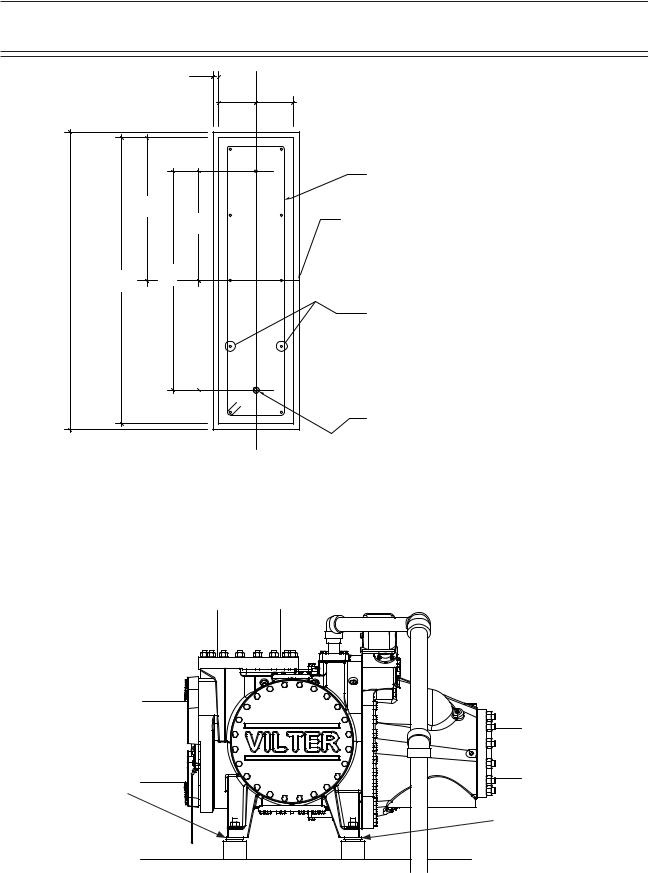
Materials needed to build the foundation are forms, concrete, sand, rebar, wire, grout, anchor bolts, expansion board and shims. A set of concrete forms will need to be acquired; generally, these can be rented or constructed from dimensional lumber. There should be enough 4,000 psi concrete with one inch aggregate to build the foundation. Also, there should be enough sand to provide a base of compacted sand four inches thick for the foundation to rest on, see Figure 1 - Concrete Pad with Compressor Unit Dimensions - Side View. The rebar required is ASTM 615, grade 60, sizes #4 and #6. Wires will also be needed to tie the rebar together. The recommended grout is Masterflow 648CP high performance non-shirk grout to provide at least a 1” thick pad under each foot. The recommended anchors are 5/8” Diameter HILTI HAS SS threaded rod for outdoor installations or HAS-E rods for indoor installations. Anchor bolts shall have a five inch projection and 12-3/8” embedment. The required adhesive is HIT-ICE/HIT/HY 150 anchoring system. There should be enough one inch expansion boards to go around the perimeter of the foundation. Finally there should be enough shim stock and extra anchor bolt nuts to level the compressor unit.
12
Foundation
Building the Foundation
Use the Vilter General Arrangement (GA) and foundation drawings to help secure a building permit and foundation construction. The Vilter GA drawing will have the necessary dimensions required to determine the overall foundation size and where to locate the compressor unit on the foundation. It will also show the dimensions required to form up the housekeeping piers that the compressor unit rests on. The Vilter foundation drawing lists the necessary information to construct a suitable foundation. It includes the rebar requirements and locations. It also shows anchor bolt locations, grouting and the concrete specifications. Using the Vilter GA drawing, Vilter foundation drawing and the information from site characteristics, site layout and safety studies will provide enough data to allow building the foundation to proceed.
The foundation is to be cast and permanently exposed against the earth. Therefore, if constructing on an existing floor, typically indoors, the floor will need to be broken up to get to the earth. If starting from undisturbed soil, it must be also be prepared accordingly. In either case, these are some check points to consider:
•Check the depth of your frost line to ensure the foundation extends below it
•Ensure the foundation rests entirely on natural rock or entirely on solid earth, but never on a combination of both
•Check the ability of the soil to carry the load
•Check wet season and dry season soil characteristics for static loading limits and elasticity
•Check local codes for Seismic Design requirements
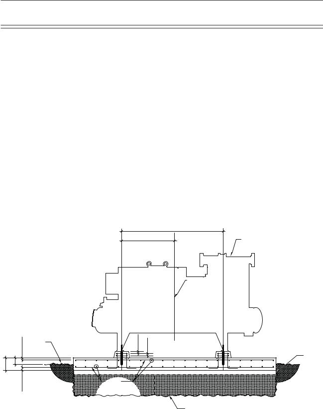
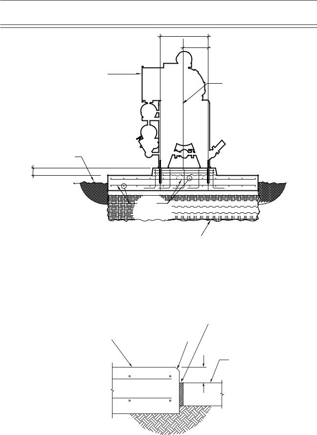
For examples of foundation diagrams, refer to Figure 1 - Concrete Pad with Compressor Unit Dimensions - Side View and Figure 2 - Concrete Pad with Compressor Unit Dimensions - Front View
G.A.
G.A. |
COMPRESSOR UNIT |
CENTER LINE OF
GAS COMPRESSION
SYSTEM
|
CLR. |
GRADE |
2"(TYP.) |
2"(TYP.) |
|
|
EL. TOP OF |
|
|
|
2" |
|
|
4" COMPACTED |
|
|
|
|
|
0" |
6" |
|
|
SAND |
|
|
|
||
1'- |
|
|
|
|
|
CLR. |
|
# 6 @ 12" |
|
|
|
EACH WAY |
|
|
|
3" |
|
|
|
|
|
TOP & BOTTOM |
|
|
|
|
|
|
|
|
|
|
|
EXCAVATE TO FROST DEPTH AS REQ'D AND BACKFILL |
|
|
|
|
WITH CLSM OR NON-FROST SUSCEPTIBLE FILL |
Figure 1. Concrete Pad with Compressor Unit Dimensions - Side View
13
Foundation
G.A.
G.A.
COMPRESSOR UNIT
CENTER LINE OF
GAS COMPRESSION
SYSTEM
EL. TOP OF
GRADE |
6" |
# 6 @ 12" 


 EACH WAY


 TOP & BOTTOM


EXCAVATE TO FROST DEPTH AS REQ'D AND BACKFILL
WITH CLSM OR NON-FROST SUSCEPTIBLE FILL
Figure 2. Concrete Pad with Compressor Unit Dimensions - Front View
Once the site has been excavated and prepared, place four inches of sand down on the bed where the foundation will rest. The sand must be compacted before placing the forms and rebar. After the sand is compacted, use the Vilter GA drawing to construct the forms for the foundation. With forms in place, install expansion boards on the inside of the forms, for example, see Figure 3 - Interior Foundation Isolation. Next, place your rebar in the forms as per the Vilter foundation drawing. When all rebars are in place the concrete can be poured. The concrete must then be trolled level and a surface texture etched in place. Leave the concrete to cure for at least 28 days.
|
|
|
|
|
|
ISOLATION JOINT, |
|
|
|
|
|
|
|
|
|
|
|
|
|
1" MINIMUM |
COMPRESSOR UNIT |
|
CHAMFER EDGE |
|
|
|
THICKNESS |
|
|
|||||
|
||||||
FOUNDATION |
|
|
|
|
|
|
|
CONCRETE |
|
SLAB IN |
6” |
BUILDING |
14 |
Figure 3. Interior Foundation Isolation |
|
Foundation
Compressor Unit Installation
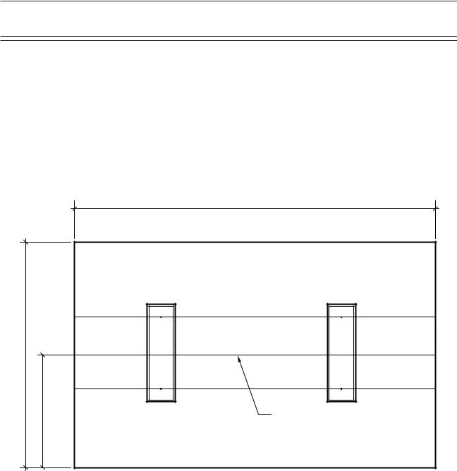
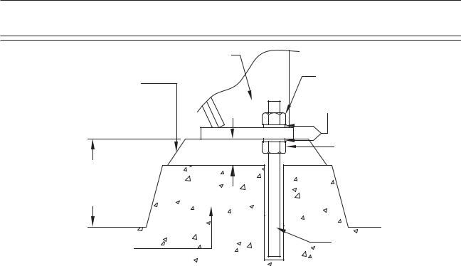
Once the foundation has cured, the compressor unit can be placed on the foundation, see Figure 4. Foundation with Housekeeping Pads Dimensions - Top View and Figure 5. Housekeeping Pad Dimension Detail - Top View. With the appropriate material handling equipment, lift the compressor unit by locations shown on the Vilter GA drawing and slowly place it on the foundation housekeeping piers. As per the Vilter GA drawing, ensure the compressor unit is correctly placed on the foundation. Once placed, use the spherical washers directly under the compressor as the surface to level the compressor unit, see Figure 6 - Compressor with Spherical Washers. Place shims under the feet of the compressor unit, as needed, until it is leveled, see Figure 7 - Concrete Pad Housekeeping Detail. Select the correct drill bit and drill thru the anchor bolt hole in the mounting feet of the compressor unit to the depth called for on the Vilter foundation drawing. Finally using the HILTI instructions, put your anchor bolts in place and wait for them to cure. Then place the nuts on the anchor bolts to finger tight and prepare to grout.
10'-0"
5'-0"
OVER ALL G.A. LENGTH + 4'-0"
CENTER LINE GAS
COMPRESSION
SYSTEM
Figure 4. Foundation with Housekeeping Pads Dimensions - Top View
15
|
|
|
Foundation |
|
|
1" (TYP.) |
|
|
|
G.A. |
G.A. |
|
|
|
(2) - # 4 |
|
|
G.A. |
CLOSED TIES |
|
|
CENTER LINE |
|
|
|
G.A. |
|
|
|
|
|
+ 2" |
G.A. |
G.A. |
|
G.A. |
|
|
(5) - # 6 VERT. |
|
|
|
|
|
|
|
WITH STD. 90° HOOK |
|
|
|
AT BOTTOM EACH |
|
|
|
FACE |
|
|
|
5/8" DIA. HILTI HAS SS THREADED ROD |
|
|
|
(HAS-E RODS ARE ACCEPTABLE FOR INTERIOR |
|
|
|
INSTALLATIONS) INSTALLED USING |
|
|
|
HIT-ICE/HIT-HY 150 ADHESIVE ANCHORING |
|
|
|
SYSTEM. |
|
|
|
(5" PROJECTION, 12 3/8" EMBEDMENT.) |
|
|
|
HOLES TO BE INSTALLED WITH HAMMER DRILL. |
|
|
|
DO NOT DIAMOND CORE. (TYP.) |
Figure 5. Housekeeping Pad Dimension Detail - Top View
SPHERICAL |
|
WASHER |
SPHERICAL |
|
|
|
WASHER |
|
Figure 6. Compressor with Spherical Washers |
16
|
Foundation |
|
70+6 .') |
010Ä5*4+0- |
*1.& &190 076 |
'21:; )4176 |
|
|
9#5*'4 |
|
.'8'.+0) 076 |
|
/+0 |
4'%1//'0&'& |
|
(14 |
|
*175'-''2+0) |
|
%10%4'6' |
#0%*14 $1.6 |
|
|
$#5' |
|
Figure 7. Concrete Pad Housekeeping Detail
Leveling and Grouting
The unit should be level in all directions. Wet the concrete pad according to the grout manufacturer’s directions. Mix a sufficient amount of grout. The grout must be an expanding grout rather than shrinking to provide a tighter bond. Follow the manufacturer’s recommendations for setting, precautions, mixing, and grout placement, finishing and curing. The grout must be worked under all areas of the feet with no bubbles or voids. If the grout is settled with a slight outside slope, oil and water can run off of the base. Once the grout has cured, torque the anchor bolts as per HILTI instructions.
Piping Connections Piping Stress
Once the screw compressor package has been installed, properly grouted and anchored, it is imperative that the piping bolted to the screw compressor not impose excessive forces on the compressor. Suction and discharge lines should be supported so the lines will not move if disconnected from the compressor.
Additional Information
Codes and Standards
Vilter followed the following codes and standards when designing your foundation:
•ACI
•ASTM
•ASCE 7
•IBC 2006
17

Foundation
Operation and Performance
The foundation was designed for:
•Outside environment severe exposure
•Ambient temperature -10 degrees F to 105 degrees F
•Unit weight 20,000 lbs
•RPM 3600
•Soil bearing capacity 1,500 lbs/sq.ft.
•Wind speed 120 MPH
•Exposure factor D
•Wind importance factor 1.15
•Concrete poured on and permanently cast against the earth
General Design Requirements
The compressor foundation is designed to:
•Maintain the compressor in alignment and at proper elevation.
•Minimize vibration and prevents its transmission to other structures
•Provide a permanently rigid support
•Provide sufficient depth to dampen vibrations.
18

Rigging and Lifting
Thank you for purchasing a gas compressor (the “Compressor”) from Vilter Manufacturing LLC (“Vilter”). Rigging and Lifting a large piece of equipment like the Compressor is extremely dangerous.
**DISCLAIMER**
Notice
This rigging and lifting manual (this “Manual”) is provided to you as a courtesy by Vilter and is not intended to be a comprehensive guide to rigging and lifting the Compressor. Vilter shall not be liable for errors contained herein or for incidental or consequential damages (including any injury to persons performing the rigging or lifting) in connection with the furnishing, performance, or use of this Manual. This Manual is only a set of suggestions and you may not rely solely on the information contained in this Manual to conduct the lift. In addition, information in this Manual is subject to change without notice.
Limited Warranty
The information is this Manual does not constitute any warranty as to the Compressor. The warranty provision contained in the terms and conditions pursuant to which the Compressor was sold serves as the sole and exclusive warranty.
Safety
To correctly and safely operate the Compressor, you must consult all of the documentation that was provided to you with the purchase of the Compressor (including all information sheets, warning notices and any other documents). This Manual is not intended to summarize or supplant any directions regarding how to safely operate or move the Compressor.
BEFORE LIFTING AND RIGGING THE COMPRESSOR
In order to minimize the inherent risk involved in rigging and lifting a large piece of equipment, before attempting to lift the Compressor, the actions of all parties involved in the lift must be carefully planned.
The following is provided merely to encourage purchasers to think about all of the steps necessary to rig and lift the Compressor. Vilter can neither anticipate all of the dangers involved in a particular lift, nor evaluate the particular capabilities of each of person who will participate in the lift.
Educate and Select Lift Participants
To rig and lift the Compressor in a safe manner, you will need to select experienced, trained people (“Participants”) to take on (and successfully perform) at a minimum the tasks associated with each of the following positions:
•Crane Operator;
•Crane Owner;
•Lift Coordinator;
•Lift Engineer;
•Rigging Specialist;
•Riggers; and
•Safety Signaler.
19

Rigging and Lifting
Training curriculum for Participants, at a minimum, should include:
•A review of safe operating practices;
•A review of who each person is and their specific role in the lift;
•A tutorial on how to read lift charts;
•A demonstration on how to use and inspect rigging hardware;
•A review of the company’s general lift plans and procedures;
•A tutorial on hand signals normally used to communicate with crane operators (a copy of such hand signals may be obtained from machine safety vendors); and
•A review of the Compressor’s specific rig and lift plan (the “Plan”) (developed by the Lift Coordinator and Lift Engineer); please see the section immediately below entitled “Create and Communicate the Plan.”
Individuals participating in the lift should fully understand the scientific principles pursuant to which a successful lift is dependent—for example, center of gravity, equilibrium, and mechanics of load stabilization, critical angle considerations and force.
All Participants should undergo a fitness-for-duty program, including drug testing and medical examinations.
Create and Communicate the Plan
Well in advance of the planned lift date, lift planning meetings and hazard assessment meetings should be held with all Participants in attendance. In addition, the Plan should be finalized and distributed for review and comment.
The Plan should clearly define requirements, expectations and specifications for lifting the Compressor. At a minimum, the Plan should include:
•Standard lifting and rigging procedures in place at the lift site (including proper classification of the lift as a “critical lift” a “serious lift” or a “standard lift”);
•Drawings of the Compressor;
•A description of the lifting task;
•An evaluation of the hazards;
•The rigging plan and sketches of rigging to be attached to the Compressor;
•The roles and responsibilities of all Participants;
•An emergency plan; and
•The contact information of the Plan preparer
It is important to confirm that each Participant understands both the broader Plan and their specific responsibilities during the lift. Participants should be encouraged to contact the Plan preparer at any time if they have questions. In addition, the Plan preparer should be on-site during the lift to ensure that the lift is being executed in accordance with the Plan. Finally, well in advance of the lift date, it should be confirmed that all necessary permits have been obtained.
Inspect and Use the Appropriate Lifting Equipment
Verify Crane Operator and Crane Owner Credentials
Prior to rigging and lifting the Compressor, certain precautions should be taken with regards to the crane, the crane operator and the crane owner.
•The lift capacity of the crane must exceed the Compressor’s weight;
•Confirm that the crane operator is qualified to work on the site;
20
Rigging and Lifting
•Get third-party confirmation that the crane owner and the crane operator are in compliance with applicable laws, regulations and internal safety standards;
•Consult with the crane owner to determine if any site preparation is required for outriggers—improper use of outriggers is a significant cause of crane failure;
•Determine the level of supervision to be supplied by the crane owner; and
•Review all crane maintenance and inspection records, including without limitation, the crane log book, maintenance records, inspection reports and the physical condition of the crane.
Take all Appropriate Measurements
•Understand and interpret the load charts;
•Review all Compressor drawings for unit size, weight, center of gravity and other specifications;
•Communicate incident response procedures in writing prior to the lift and verbally immediately before the lift;
•Determine the initial position, final position, orientation and elevation of the Compressor;
•Ensure that adequate space is provided to safely assemble, erect, and operate the crane and materials (such as timber mats, cribbing and blocks);
•Identify and communicate to all Participants the access points, lift radius, swing radius, clearances, and obstructions;
•Eliminate hazards and obstructions that may interfere with moving the Compressor; and
•Inform all Participants of water lines, sewer lines, power lines and other obstructions.
Use Proper Rigging Methods
•Determine diameter, length and quantity of necessary rigging hardware (design and detail the rigging hardware to suit lifting the Compressor at the supplied pad eyes);
•Review and inspect all hoisting, lifting and rigging equipment;
•Select shackle size and prepare sketches or drawings for rigging;
•Use proper, conservative rigging techniques—including spreader beams—needed to lift the Compressor;
•Pad sharp corners, check the orientation of chocker hitches and the orientation of hooks;
•Prevent the binding of hoist rings; and
•Verify pad eye information.
TEST AND BALANCE THE COMPRESSOR
It is essential to test and balance the compressor before executing the actual lift in order to identify potential causes of injury to Participants and the Compressor.
Secure Rigging and the Lift Site
•Reiterate that no one should walk under the raised load;
•Secure and restrict access to the lift area (consider vacating all non-essential personnel from the area);
•Provide qualified supervision for the duration of the lift;
•If applicable, assess the weather conditions and decide if it is safe to proceed;
•Stop the lift when any potentially unsafe conditions are recognized; and
•Ensure there are open channels for communications during the pre-lift, lift and post-lift phases (radio communications should be used if a direct line of sight is not possible).
Test and Balance the Compressor before the Lift
•Slowly raise the crane to take slack out of the rigging without actually lifting the load;
•Allow the rigging gear to settle into place;
•Check for twists and binds;
•Verify that all padding has remained in place and that all slings are protected from sharp edges;
•Begin to raise the load to verify balance and check the braking system; and
•If the Compressor is not balanced, lower and adjust as necessary.
21

Rigging and Lifting
CONTACT VILTER
While Vilter will not offer any specific feedback on the Plan or provide a specific Plan for rigging and lifting the Compressor, Vilter may be able to answer questions about the Compressor that are important in developing your Plan.
Please contact Vilter at:
P.O. Box 8904
5555 S Packard Ave
Cudahy, WI 53110-8904
Telephone: 1-414-744-0111
Fax: 1-414-744-3483
email: info.vilter@emerson.com
www.vilter.com
22

Installation
I.DELIVERY INSPECTION
Vilter screw compressor components are thoroughly inspected at the factory, assuring the shipment of a mechanically perfect piece of equipment. Damage can occur in shipment, however. For this reason, the units should be thoroughly inspected upon arrival. Any damage noted should be reported immediately to the transportation company. This way, an authorized agent can examine the unit, determine the extent of damage and take necessary steps to rectify the claim with no serious or costly delays. At the same time, the local Vilter representative or the home office should be notified of any claim made.
TABLE 1. |
UNIT WEIGHTS (LBS)* |
|
MODEL |
STANDARD |
ECON-O- |
|
|
MIZER |
VSM 71 |
2,750 |
2,750 |
VSM 91 |
2,750 |
2,750 |
VSM 101 |
2,750 |
2,750 |
VSM 151 |
2,750 |
2,750 |
VSM 181 |
2,750 |
2,750 |
VSM 201 |
2,750 |
2,750 |
VSM 301 |
2,850 |
2,850 |
VSM 361 |
2,850 |
2,850 |
VSM 401 |
2,850 |
2,850 |
VSM 501 |
4,000 |
4,000 |
VSM 601 |
4,500 |
4,500 |
VSM 701 |
5,000 |
5,000 |
VSS 451 |
4,000 |
4,000 |
VSS 601 |
4,500 |
4,500 |
VSS 751 |
5,300 |
5,300 |
VSS 901 |
5,300 |
5,300 |
VSS 1051 |
6,600 |
6,600 |
VSS 1201 |
6,700 |
6,700 |
VSS 1301 |
6,750 |
6,750 |
VSS 1501 |
10,010 |
10,010 |
VSS 1801 |
10,010 |
10,010 |
VSS 1551 |
11,000 |
11,000 |
VSS 1851 |
11,000 |
11,000 |
VSS 2101 |
11,000 |
11,000 |
* Does not include motor.
II.FOUNDATIONS
Vilter single screw compressor units are basically vibration free machines, therefore, no elaborate foundations are necessary. The floor or foundation upon which the unit will be placed should be designed to support the entire operating weight of the unit. See Table 1 for unit weights. See Foundation, page 12, for additional foundation instructions.
III.LOCATING UNIT - DRIVE COUPLING ALIGNMENT
The single screw compressor units are shipped with all major components mounted on structural steel. Place the entire unit on the floor on a concrete pad and securely bolt in place. Review local codes and ASHRAE Safety Code for Mechanical Refrigeration. Bolt holes are located in the unit’s mounting feet. When locating the unit, provide adequate space for service work. When the compressor unit is in place on the concrete pad, check both lengthwise and crosswise to assure it is level. Use shims and wedges as needed under the mounting feet to adjust the level of the unit.
On single screw units, the motor and compressor have been roughly aligned at the factory. The coupling center section was shipped loose to allow a check of proper electrical phasing, direction of rotation of the motor and final coupling alignment. The dial indicator alignment method is recommended. Final alignment should be within 0.004 inches total indicator reading in all direction for the VSS models and 0.010 inches for the VSM models.
III.SYSTEM PIPING
Refer to the ANSI/ASME B31.5 Code for Refrigeration Piping. All compressor oil supply and oil return piping has been completed at the factory. The necessary connections to be made to the screw compressor unit will vary depending on the type of oil cooling method purchased. Main line refrigerant suction and discharge connections are always necessary.
23

Installation
Care must be taken to avoid trapping the lines except for specific purposes. When traps are used, the horizontal dimensions should be as short as possible to avoid excessive oil trapping.
Lines for ammonia systems must be of steel pipe with specially designed ammonia service fittings. Common pipe fittings must NEVER be used as they will not provide the same service. Steel pipe is generally used in large installations when joints are welded.
In making up joints for steel pipe, the following procedures should be followed:
For threaded connections, all threads on the pipe and fitting should be carefully cleaned to remove all traces of grease or oil. Threads should then be wiped dry with a lintless cloth. Only thread filling compounds suitable for refrigeration service should be used for making steel pipe joints. These compounds should be used sparingly, and on the pipe only. Do not put any on the first two threads to prevent any of the compound from entering the piping system. Acetylene or arc welding is frequently used in making steel pipe joints, however, only a skilled welder should attempt this kind of work. Take care to see no foreign materials are left in the pipes and remove all burrs formed when cutting pipe.
It is important to avoid short, rigid pipe lines that do not allow any degree of flexibility. This must be done to prevent vibration being transmitted through the pipe lines to the buildings. One method of providing the needed flexibility to absorb the vibration is to provide long lines that are broken by 90° Ells in three directions.
Smaller Halocarbon and Hydroflourocarbon installations use copper pipes with solder type fittings where possible. The use of screw type fittings in Halocarbon systems should be held to an absolute minimum, as these refrigerants, due to their physical properties, will leak through screw type joints.
When drawn copper tubing is used for Halocarbon lines, type “K” or “L” conforming to ASTM B88 should be used. Soft annealed copper tubing conforming to ASTM B280 can also be used
for tube sizes not larger than 1-3/8” in outside diameter. These requirements are in accordance with the mechanical code for refrigeration ANSI B9.1-1971. The type of copper tubing to be used for a given pressure is dependent on the strength of the copper at the design temperature. Some local codes forbid the use of Type “L”. Therefore, before installation, be sure to check local requirements. Never use type “M” as it does not have adequate wall thickness to withstand the operating pressures. In selecting fittings for Halocarbon piping, only wrought copper fittings should be used. Cast fittings as used for water service are porous and will allow the refrigerant to escape. Note this exception: In larger pipe sizes, wrought fittings are not available. However, specially tested cast fittings are available and these may be used with complete safety.
In larger pipe sizes, wrought fittings are not available. However, specially tested cast fittings are available and these may be used with complete safety.
When soldering copper tubing joints, only silver solder should be used for Refrigerant-22 service. Soft solder such as “50-50” should never be used, as its melting point is too low, lacks mechanical strength, and tends to break down chemically in the presence of moisture.
A second method would be to install flexible pipe couplings as close to the compressor unit as possible with connections run in two different directions, 90° apart. These flexible connections should be installed on both the high and low side lines of the compressor unit.
Hangers and supports for coils and pipe lines should receive careful attention. During prolonged operation of the coils, they may become coated with ice and frost, adding extra weight to the coil. The hangers must have ample strength and be securely anchored to withstand the vibration from the compressor and adequately support the pipe lines.
Water supply and drain connections, and equipment using water, should be installed so all the water may be drained from the system after the plant has been shut down in cold weather.
24

Installation
These precautions will avoid costly damage to the equipment due to freezing.
This information is taken from ASHRAE 15-89 and ANSI B31.5. The installing contractor should be thoroughly familiar with these codes, as well as any local codes.
IV. |
ELECTRICAL CONNECTIONS |
The single screw compressor units are shipped with all package mounted controls wired. The standard control power is 115 volts 60 Hertz, single phase. If a 115 volt supply is not available, a control transformer may be required. The power source must be connected to the control panel according to the electrical diagrams.
The units are shipped without the compressor motor starter. Field wiring is required between the field mounted starters and package mounted motors.
Additional control wiring in the field is also required. Dry contacts are provided in the control panel for starting the screw compressor motor. These contacts are to be wired in series with the starter coils. A current transformer is supplied along with the compressor unit, and is located in the motor junction box. This transformer is to be installed around one phase of the compressor motor starter. A normally open auxiliary contact from the compressor motor starter is also required.
Terminal locations for this wiring can be found on the wiring diagram supplied with this unit. Additional aspects of the electrical operation of the single screw units are covered in the start up and operation section of this manual.
V.TESTING REFRIGERATION SYSTEM FOR LEAKS
Vilter equipment is tested for leaks at the factory. One the most important steps in putting a refrigeration system into operation is field testing for leaks. This must be done to assure a tight system that will operate without any appreciable loss of refrigerant. To test for leaks, the system pressure must be built up. Test pressures for various
refrigerants are listed in ANSI B9.1-1971 code brochure entitle “Safety Code for Mechanical Refrigeration”. These pressures will usually suffice, however, it is advisable to check local codes as they may differ. Before testing may proceed, several things must be done.
First, if test pressures exceed the settings of the system, relief valves or safety devices, they must be removed and the connection plugged during the test. Secondly, all valves should be openedexceptthoseleadingtotheatmosphere. Then, open all solenoids and pressure regulators by the manual lifting stems. All bypass arrangements must also be opened. Because of differences in characteristics of the various refrigerants, two different testing methods are necessary.
A.Ammonia Systems
Dry nitrogen may be used to raise the pressure in an ammonia system to the proper level for the test. The gas may be put into the system through the charging valve or any other suitable opening. Adjust the pressure regulator on the bottle to prevent over-pressurization. Do not exceed the pressure rating on the vessel with the lowest pressure rating.
Carbon Dioxide should NOT be used as a testing gas in a system where ammonia is already dissolved in any moisture remaining. This will cause ammonium carbonate to precipitate when the CO2 is added. If heavy enough, this precipitate may cause the machine to freeze and clog the strainer.
A mixture of four parts water to one part liquid soap, with a few drops of glycerin added, makes a good solution. Apply this mixture with a one inch round brush at all flanges, threaded joints, and welds. Repair all visible leaks. If possible, leave the pressure on over night. A small pressure drop of 5 lbs. Over this period indicates a very tight system.
Remember to note the ambient temperature, as a change in temperature will cause a change in pressure.
After the system is thoroughly tested, open all
25

Installation
valves on the lowest part of the system so the gas will float away from the compressor. This prevents any dirt or foreign particles from entering the compressor and contaminating the working parts. The oil should then be charged into the compressor.
Charge a small amount of ammonia into the system and pressurize the system to its respective design pressure. Pass a lit sulfur stick around all joints and connections. Any leaks will be indicated by a heavy cloud of smoke. If any leaks are observed during this test, they must be repaired and rechecked before the system can be considered tight and ready for evacuation.
B.Halocarbon Refrigerant Systems
“Oil pumped” dry nitrogen, or anhydrous CO2 in this order of preference may be used to raise the pressure to the proper level for testing.
When the proper pressure is attained, test for leaks with the soap mixture previously described. After all leaks are found and marked, relieve the system pressure and repair the leaks. Never attempt to repair soldered or welded joints while the system is under pressure. Soldered joints should be opened and re soldered.
Do not simply add more solder to the leaking joint. After all the joints have been repaired and the system is considered “tight” the system may be tested with refrigerant.
Attach a drum of the refrigerant to be used in the system and allow the gas to enter until a pressure of 5 psig is reached.
Remove the refrigerant drum and bring the pressure to the recommended test level with oil pumped dry nitrogen or CO2. Then check the entire system again for leaks, using a halide torch or electronic leak detector. Be sure to check all flanged, welded, screwed and soldered joints, all gasketed joints, and all parting lines on castings. If any leaks are found, they must be repaired and rechecked before the system can be considered tight again, remembering that no repair should be made to welded or soldered joins while the system is under pressure.
C.Evacuating The System
A refrigeration system operates best when only refrigerant is present. Steps must be taken to remove all air, water, vapor, and all other noncondensables from the system before charging it with refrigerant. A combination of moisture and refrigerant, along with any oxygen in the system, can form acids or other corrosive compounds that corrode internal parts of the system.
To properly evacuate the system, and to remove all non-condensables, air and water vapor, use a highvacuumpumpcapableof attainingablanked off pressure of 50 microns or less. Attach this pump to the system and allow it to operate until system pressure is reduced somewhere below 1000 microns. Evacuation should not be done unless the room temperature is 60F or higher.
Attach vacuum gauge(s), reading in the 20 to 20,000 micron gauge range, to the refrigerant system. These gauge(s) should be used in conjunction with the high vacuum pump. The reading from the gauge(s) indicates when the system has reached the low absolute pressure required for complete system evacuation.
Connect the high vacuum pump into the refrigeration system by using the manufacturer’s instructions. Connect the pump both to the high side and low side of the system, to insure system evacuation. Attach the vacuum gauge to the system in accordance with the manufacturer’s instructions.
A single evacuation of the system does not satisfactorily remove all of the non-condensable, air and water vapor. To do a complete job, a triple evacuation is recommended.
When the pump is first turned on, bring system pressure to as low a vacuum level as possible, and continue operation for 5 to 6 hours.
Stop the pump and isolate the system. Allow the unit to stand at this vacuum for another 5 to 6 hours. After this time, break, the vacuum and bring the system pressure up to 0 psig with dry nitrogen.
26

Installation
To begin the second evacuation, allow the pump to operate and reduce the pressure again to within 50 to 1000 microns. After this reading is reached, allow the pump to operate 2 or 3 hours. Stop the pump and let the system stand with this vacuum. Again using dry nitrogen, raise the system pressure to zero.
For the third evacuation, follow the previous procedure with the pump operating until system pressure is reduced below the 1000 micron level. Run the pump an additional 6 hours and hold the system for approximately 12 hours at low pressure. After this, again break the vacuum with dry nitrogen and allow the pressure in the system to rise slightly above zero pounds (psig). Install new drier cartridges and moisture indicators. Charge the system once more below the 1000 micron level and use the refrigerant designed for the system.
When properly evacuating the system as outlined above, the system is dry, oxygen-free and free of non-condensables. The piping should not be insulated before the evacuation process is started. If moisture is in the system before evacuating, it condenses in low places and freezes. If this happens, it can be removed by gently heating the trap farthest away from the vacuum pump. This causes the ice to melt and water to boil. Water vapor collects in the next trap towards the vacuum pump. This process should be repeated until all pockets of water have been boiled off, and the vacuum pump has had a chance to remove all the water vapor from the system.
VI. |
UNIT OIL CHARGING |
The compressor unit is shipped from Vilter with no oil charge. The initial oil charge can be made through the drain valve at the oil receiver/separator. Vilter motor driven and manually operated oil chargers are available for this purpose. Once the unit has been started and is operating above 50% capacity, oil may have to be added to bring the oil level to the normal operating point. With the unit operating, oil should be added through the charging connection at the suction strainer. The normal operating level is between the (2) sight glasses on the oil separator. See Table 2 for approximate oil charge requirements.
TABLE 2. |
OIL CHARGE |
Oil Separator Size |
Approximate Oil |
|
Charge (Gallons) |
VSR 16” |
20 to 27 |
VSR 20” |
22 to 31 |
VSM 20” |
20 to 25 |
VSM 30” |
30 to 35 |
20” |
30 to 40 |
24” |
40 to 50 |
30” |
60 to 75 |
36” |
95 to 105 |
42” |
145 to 165 |
The oil level may be above the top sight glass at this time. Later, when the unit is placed in operation, there will be some drop in the oil level as the various oil lines, oil filter and other piping becomes charged with the normal amount of oil that will be in circulation. This drop in oil level should bring the level in the oil receiver/ separator into the normal operating range. Do not mix oils.
A.Oil For Single Screw Compressors
Due to the need for adequate lubrication, Vilter recommends only the use of Vilter lubricants, designed specifically for Vilter compressors. With the extensive research that has been performed, we are able to offer refrigerant specific lubricating oils. Use of oil not specified or supplied by Vilter will void the compressor warranty.
Please contact your local Vilter representative or the Home Office for further information.
VII. |
SYSTEM REFRIGERANT CHARGING |
CAUTION
When charging the system, make sure the compressor unit is pressurized from the discharge side of the compressor. Pressurizing the compressor from the suction side may cause rotation of the compressor, without oil supply, which could lead to internal damage.
27

Installation
After the system is leak-free and evacuation has been completed, it is ready for charging. Before actual charging, however, the entire operation of the refrigeration system should be inspected as outlined below:
A.Low Side Equipment
1.Fans on air handling equipment running.
2.Pumps on water cooling equipment running.
3.Proper location and attachment of thermostatic expansion valve bulb to suction line.
4.Correct fan and pump rotation.
5.Evaporator pressure regulators and solenoid valves open.
6.Water pumps and motors correctly aligned.
7.Belt drives correctly aligned and tensioned.
8.Proper voltage to motors.
B.Compressors
1.Proper oil level.
2.Voltage agrees with motor characteristics.
3.Properly sized motor fuses and heaters.
4.Direct drivers aligned and couplings tight.
5.All suction and discharge valves open.
6.All transducers and RTD’s calibrated and reading correctly.
C.Condensers
1.Water available at water cooled condensers and supply line valve open.
2.Water in receiver of evaporative condenser and makeup water available.
3.Correct rotation of pump and fan motors.
4.Belt drives aligned and tensioned correctly.
5.Pump, fans and motors lubricated.
D.Controls
Controls should be at the initial set points. See microprocessor manual for further information.
E.Initial Charging – High Side Charging
There are two methods of charging refrigerant into the system, through the “high side” or through the “low side”. High side charging is usually used for initial charging as filling of the
system is much faster. Low side charging is usually reserved for adding only small amounts of refrigerant after the system is in operation.
High side charging of refrigerant into the system is accomplished as follows:
1.Connect a full drum of refrigerant to the liquid charging valve. This valve is generally located in the liquid line immediately after the king or liquid line valve. Purge the air from the charging line.
2.Invert the refrigerant drum if the drum is not equipped with “Liquid” and “Vapor” valves, and place in such a position so the liquid refrigerant only can enter the system. Close the liquid line or king valve, if it is not already closed. Open the “Liquid” charging valve slowly to allow refrigerant to enter the system. The vacuum in the system will draw in the refrigerant.
It is important that, during this operation, air handling units be running and water is circulating through the chillers. The low pressures on the system can cause the refrigerant to boil at low temperature and possibly freeze the water if it is not kept circulating.
Water freezing in a chiller can rupture the tubes and cause extensive damage to the system. It would be desirable to charge the initial amount of refrigerant without water in the shell and tube equipment to eliminate the possibility of freeze up.
3.After some refrigerant has entered the system, the compressor unit starting procedure may be followed. See Start-Up and Operation Section of this manual.
4.Continue charging refrigerant into the system until the proper operating requirements are satisfied. Then, close the liquid charging connection and open the liquid line valve allowing the system to operate normally. To check that enough refrigerant has been added, the liquid sight glass
28

Installation
should show no bubbles, and there will be a liquid seal in the receiver. If these two conditions are not satisfied, additional refrigerant must be added.
5.When sufficient refrigerant has been charged into the system, close the charging and drum valves. Then remove the drum from the system.
6.During the charging period, observe the gauge carefully to insure no operating difficulties. Watch head pressures closely to make sure the condensers are functioning properly.
Since it is usually necessary to use several drums when charging a system, follow the procedures in paragraphs E1 and E2 of the above description when attaching a new drum. After charging, the refrigerant drums should be kept nearby for several days as it is sometimes necessary to add more refrigerant as the system “settles down”.
VIII. MAINTENANCE SUGGESTIONS
Careful checking of a refrigeration system for leaks and proper operation of all components upon installation will start the system on its way to a long life of satisfactory service. To ensure the desired trouble-free operation, however, a systematic maintenance program is a prerequisite. The following maintenance schedule is suggested.
A.Daily
1.Check oil levels.
2.Check all pressure and temperature readings.
3.Check micronic oilfilter inlet and outlet pressures for excessive pressure drop. Change filter when pressure drop exceeds 45 psi or every six months, whichever occurs first. For proper procedure for changing micronic oil filter and for charging oil into the system, see Operation Section.
4.Clean strainers each time filter cartridge if replaced.
5.Check compressor sound for abnormal noises.
6.Check shaft seals for excessive oil leakage. A small amount of oil leakage (approximately 10 drops/min) is normal. This allows lubrication of the seal faces.
B.Weekly
(Items 1 thru 6 above plus 7 thru 9)
7.Check the refrigeration system for leaks with a suitable leak detector.
8.Check oil pressures and review microprocessor log and log sheets.
9.Check refrigerant levels in vessels.
C.Monthly
(Items 1 thru 8 above plus 9 thru 13)
10.Oil all motors and bearings. Follow manufacturer’s instructions on lubrication.
11.Check calibration and operation of all controls, particularly safety controls.
12.Check oil cooler for any evidence of corrosion, scaling or other fouling.
13.Operatecompressorcapacityandvolume ratio controls through their range both automatically and manually.
D.Trimonthly
(About 2000 operating hours)
Check movement of compressor rotor at drive coupling end to determine bearing float. (Refer to Service Section.)
E.Yearly
(Items 1 thru 13 and “D” above plus 14 thru 28)
14. Check entire system thoroughly for leaks.
29

Installation
15.Remove all rust from equipment, clean and paint.
16.Flush out sediment, etc. from water circuits.
17.Clean all oil strainers.
18.Clean suction strainer – compressors.
19.Check motors and fans for shaft wear and end play.
20.Check operation and general condition of microprocessor and other electrical controls.
21.Clean all water strainers.
22.Check drains to make sure water will flow away from equipment.
23.Drain and clean entire oil system at receiver drain. Recharge with new clean moisture free oil. For proper procedure for changing micronic oil filter and charging oil into the system, see Start-Up and Operation section.
24.Check compressor coupling. For integrity and alignment.
25.Check oil pump for wear.
26.Check the calibration of the microprocessor pressure transducers and RTD’s for accuracy.
27.Check mounting bolts for compressor and motor.
F.System Leaks
There are any number of reasons why leaks develop in a refrigeration system (i.e. such as drying out of valve packing, yielding of gaskets, improper replacement of valve caps and loosening of joints due to vibration). For these reasons, the need for periodic leak testing cannot be overemphasized. Similarly, when any service operations are performed on the system, care should be exercised to insure all opened flanges are
tightened, all plugs that were removed are replaced with a suitable thread filling compound, all packing glands on valve stems are tightened, and all valve caps are replaced. When operation is restored, all joints opened or any valves moved during the servicing should be checked for leaks.
G. Year Round Operation
On a continual basis:
1.Guard against liquid slugging of compressor.
2.Maintain unit in clean condition and paint as necessary.
3.Grease valve stems and threads for the valve caps.
When refrigeration equipment is operated 24 hours a day year round, it is highly recommended that a yearly check of all internal parts be made (see Service Section). While the highest material standards are maintained throughout all Vilter compressors, continuous operation and any presence of dirt may prove injurious to the machine. To forestall needless shutdowns or prevent possible machine breakdowns, the side covers should be removed yearly, and a visual inspection be made of the internal parts. In this way, a small amount of time spent checking machine conditions once a year may prevent extensive shutdowns later with subsequent product loss and expensive repairs.
30
 Loading...