


VSG/VSSG compressor unit
Installation, operation & maintenance manual

VSG/VSSG Standard Vilter Warranty Statement
Seller warrants all new single screw gas compression units and bareshaft single screw compressors manufactured by it and supplied to Buyer to be free from defects in materials and workmanship for a period of (a) eighteen (18) months from the date of shipment or (b) twelve (12) months from the date of installation at the end user’s location, whichever occurs first.
If within such period any such product shall be proved to Seller’s satisfaction to be defective, such product shall be repaired or replaced at Seller’s option. Such repair or replacement shall be Seller’s sole obligation and Buyer’s exclusive remedy hereunder and shall be conditioned upon (a) Seller’s receiving written notice of any alleged defect within ten (10) days after its discovery, (b) payment in full of all amounts owed by Buyer to Seller and (c) at Seller’s option, Buyer shall have delivered such products to Seller, all expenses prepaid to its factory. Expenses incurred by Buyer in repairing or replacing any defective product (including, without limitation, labor, lost refrigerant or gas and freight costs) will not be allowed except by written permission of Seller. Further, Seller shall not be liable for any other direct, indirect, consequential, incidental, or special damages arising out of a breach of warranty.
This warranty is only applicable to products properly maintained and used according to Seller’s instructions. This warranty does not apply (i) to ordinary wear and tear, damage caused by corrosion, misuse, overloading, neglect, improper use or operation (including, without limitation, operation beyond rated capacity), substitution of parts not approved by Seller, accident or alteration, as determined by Seller or (ii) if the product is operated on a gas with an H2S level above 100 PPM. In addition, Seller does not warrant that any equipment and features meet the requirements of any local, state or federal laws or regulations. Products supplied by Seller hereunder which are manufactured by someone else are not warranted by Seller in any way, but Seller agrees to assign to Buyer any warranty rights in such products that Seller may have from the original manufacturer. Labor and expenses for repair are not covered by warranty.
THE WARRANTY CONTAINED HEREIN IS EXCLUSIVE AND IN LIEU OF ALL OTHER REPRESENTATIONS AND WARRANTIES, EXPRESS OR IMPLIED, AND SELLER EXPRESSLY DISCLAIMS AND EXCLUDES ANY IMPLIED WARRANTY OF MERCHANTABILITY OR IMPLIED WARRANTY OF FITNESS FOR A PARTICULAR PURPOSE.
Any description of the products, whether in writing or made orally by Seller or Seller’s agents, specifications, samples, models, bulletins, drawings, diagrams, engineering sheets or similar materials used in connection with Buyer’s order are for the sole purpose of identifying the products and shall not be construed as an express warranty. Any suggestions by Seller or Seller’s agents regarding use, application or suitability of the products shall not be construed as an express warranty unless confirmed to be such in writing by Seller.
VSG/VSSG • Installation, Operation and Maintenance Manual •Vilter/Emerson • 35391SSG |
i |

Important Message
READ CAREFULLY BEFORE INSTALLING AND STARTING YOUR COMPRESSOR.
The following instructions have been prepared to assist in installation, operation and removal of Vilter Single Screw Compressors. Following these instructions will result in a long life of the compressor with satisfactory operation.
The entire manual should be reviewed before attempting to install, operate, service or repair the compressor.
A compressor is a positive displacement machine. It is designed to compress gas. The compressor must not be subjected to liquid carry over. Care must be exercised in properly designing and maintaining the system to prevent conditions that could lead to liquid carry over. Vilter Manufacturing is not responsible for the system or the controls needed to prevent liquid carry over and as such Vilter Manufacturing cannot warrant equipment damaged by improperly protected or operating systems.
Vilter screw compressor components are thoroughly inspected at the factory. However, damage can occur in shipment. For this reason, the equipment should be thoroughly inspected upon arrival. Any damage noted should be reported immediately to the Transportation Company. This way, an authorized agent can examine the unit, determine the extent of damage and take necessary steps to rectify the claim with no serious or costly delays. At the same time, the local Vilter representative or the home office should be notified of any claim made.
All inquires should include the Vilter sales order number, compressor serial and model number. These can be found on the compressor name plate on the compressor.
All requests for information, services or parts should be directed to:
Vilter Manufacturing LLC
Customer Service Department
P.O. Box 8904
5555 South Packard Ave
Cudahy, WI 53110-8904 USA Telephone: 1-414-744-0111 Fax:1-414-744-3483
e-mail: info.vilter@emerson.com
Equipment Identification Numbers:
Vilter Order Number: _______________________Compressor Serial Number: _________________
Vilter Order Number: _______________________Compressor Serial Number: _________________
Vilter Order Number: _______________________Compressor Serial Number: _________________
Vilter Order Number: _______________________Compressor Serial Number: _________________
ii |
VSG/VSSG • Installation, Operation and Maintenance Manual •Vilter/Emerson • 35391SSG |

Table of Contents
Section Title |
Section Number |
VSG/VSSG Standard Vilter Warranty Statement ..................................................................................... |
i |
Important Message................................................................................................................................ |
ii |
Section 1 • General Information |
|
How To Use This Manual......................................................................................................................... |
1-1 |
Gas Compressor Unit Model Designations.............................................................................................. |
1-2 |
System Unit Identification ..................................................................................................................... |
1-3 |
Compressor Unit Component Identification........................................................................................... |
1-4 |
Piping & Identification Component Tags................................................................................................. |
1-7 |
Symbols and Identification..................................................................................................................... |
1-8 |
Section 2 • Theory of Operation |
|
Gas Flow ................................................................................................................................................ |
2-1 |
Oil Life and Oil Flow................................................................................................................................ |
2-1 |
Oil Pressure Regulating .......................................................................................................................... |
2-2 |
Control System ...................................................................................................................................... |
2-2 |
RTDs and Pressure Transducers .............................................................................................................. |
2-2 |
Section 3 • Installation |
|
Delivery Inspection ................................................................................................................................ |
3-1 |
Rigging and Lifting................................................................................................................................. |
3-1 |
Short Term Storage Recommendations.................................................................................................. |
3-2 |
Long Term Storage Recommendations................................................................................................... |
3-2 |
Compressor Motor..................................................................................................................... |
3-2 |
Air Cooled Oil Coolers ................................................................................................................ |
3-3 |
Compressor Unit Inspections Prior to Stoarge or Installation.................................................................. |
3-3 |
Recommended Onsite Tools .................................................................................................................. |
3-3 |
Long Term Storage Log .......................................................................................................................... |
3-4 |
Foundation ............................................................................................................................................ |
3-5 |
Piping .................................................................................................................................................. |
3-10 |
Header Piping and Drains........................................................................................................... |
3-10 |
Remote Air Cooled Oil Cooler Piping .......................................................................................... |
3-10 |
General Installation Guideline for Multiple Air Coolers Installed in a Common Area ................................ |
3-12 |
Free Flow ................................................................................................................................... |
3-12 |
One Fan Diameter...................................................................................................................... |
3-12 |
Intake Velocity........................................................................................................................... |
3-12 |
Hot Air Recirculation.................................................................................................................. |
3-14 |
Pressure Testing..................................................................................................................................... |
3-16 |
Initial Oil Charging ................................................................................................................................. |
3-16 |
Using Non-Vilter Oils.................................................................................................................. |
3-16 |
Unit Oil Charging and Priming.................................................................................................... |
3-16 |
Priming Oil Cooler (Shell and Tube)and Piping............................................................................ |
3-16 |
Priming Compressor and Oil Filters ............................................................................................ |
3-18 |
Priming Remote Oil Cooler and Piping (Initial Oil Charging)........................................................ |
3-20 |
Priming Compressor and Oil Filters ............................................................................................ |
3-21 |
Pre Start-Up ........................................................................................................................................... |
3-22 |
Start-Up................................................................................................................................................. |
3-24 |
VSG/VSSG • Installation, Operation and Maintenance Manual •Vilter/Emerson • 35391SSG |
TOC - 1 |

Table of Contents |
|
|
|
|
|
Section Title |
Section Number |
Section 4 • Operation |
|
Oil Inspection ........................................................................................................................................ |
4-1 |
Dual Oil Filters........................................................................................................................................ |
4-1 |
Control System Calibration .................................................................................................................... |
4-2 |
Starting, Stopping and Restarting the Compressor ................................................................................ |
4-2 |
Calibrate Slide Valve Actualors ............................................................................................................... |
4-2 |
Oil Temperature Control Valve (Oil Mixing Valve) Operation................................................................... |
4-7 |
Manual Override ........................................................................................................................ |
4-8 |
Purging with Dry Nitrogen ..................................................................................................................... |
4-9 |
Purging with Dry Gas ............................................................................................................................. |
4-11 |
Coalescing Oil Return Line Setup............................................................................................................ |
4-14 |
Section 5 • Maintenance/Service |
|
Maintenance and Service Schedule ........................................................................................................ |
5-1 |
Maintaining Proper Operation................................................................................................................ |
5-2 |
Compressor Unit Isolation for Maintenance/Service ............................................................................... |
5-3 |
Compressor Unit Leak Check.................................................................................................................. |
5-3 |
Oil System Components......................................................................................................................... |
5-4 |
Oil Sampling............................................................................................................................... |
5-4 |
Oil Charging ............................................................................................................................... |
5-5 |
Oil Draining................................................................................................................................ |
5-6 |
Oil Filter Replacement ................................................................................................................ |
5-6 |
Coalescing Oil Filter Replacment................................................................................................. |
5-8 |
Oil Pump Strainer ....................................................................................................................... |
5-9 |
Drive Coupling (Form-Flex BPU) Installation........................................................................................... |
5-10 |
Drive Center Member (Form-Flex BPU) Installation and Alignment ......................................................... |
5-11 |
Drive Coupling (Form-Flex BPU) Removal............................................................................................... |
5-13 |
Drive Coupling (Type C Sure-Flex) Replacement ..................................................................................... |
5-13 |
Compressor Replacement ...................................................................................................................... |
5-14 |
Compressor Bearing Float Inspections ................................................................................................... |
5-16 |
Gate Rotor Float and Gate Rotor Bearing Float Inspection....................................................................... |
5-17 |
Gate Rotor and Support Clearance ......................................................................................................... |
5-19 |
Gate Rotor Assembly Replacement (All VSG & VSSG Compressors Except VSG 301-701 Compressors)....5-21 |
|
Gate Rotor Assembly Replacement (VSG 301-701 Compressors ONLY)................................................... |
5-24 |
Gate Rotor Disassembly ......................................................................................................................... |
5-26 |
Gate Rotor Blade Removal/Installation ....................................................................................... |
5-26 |
Gate Rotor Thrust Bearing Removal/Installation ......................................................................... |
5-27 |
Gate Rotor Roller Bearing Removal/Installation........................................................................... |
5-27 |
Slide Valve Actuator Assembly Replacement .......................................................................................... |
5-28 |
Command Shaft Assembly Replacement................................................................................................ |
5-29 |
Command Shaft Seal Replacement......................................................................................................... |
5-29 |
Section 6 • Troubleshooting |
|
Table 6-1. Slide Valve Actuator Troubleshooting Guide........................................................................... |
6-1 |
Table 6-2. Slide Valve Actuator LED Blink Codes...................................................................................... |
6-3 |
Table 6-3. Troubleshooting Guide - General Problems & Solutions .......................................................... |
6-5 |
TOC - 2 |
VSG/VSSG • Installation, Operation and Maintenance Manual •Vilter/Emerson • 35391SSG |

List of Tables and Figures
Section Title |
|
Section Number |
|
Section 7 • Warranty and Parts |
|
Warranty Claim Processing .................................................................................................................... |
7-1 |
|
On Site Service Support ......................................................................................................................... |
7-1 |
|
Remanufactured Bare Shaft Compressors Process.................................................................................. |
7-2 |
|
Explanation of Rebuild Levels ..................................................................................................... |
7-2 |
|
Bare Shaft Compressor Description............................................................................................ |
7-2 |
|
|
Appendices |
|
Appendix A |
Torque Specifications...................................................................................................... |
A |
Appendix B |
Motor (Compressor) General Storage Instructions .......................................................... |
B |
Appendix C |
Oil Analysis Report.......................................................................................................... |
C |
Appendix D |
Recommended Header Piping ........................................................................................ |
D |
Appendix E |
Recommended Remote Air Cooled Oil Cooler Piping....................................................... |
E |
Table/Figure |
Section Number |
Tables |
|
Table 3-1. Long Term Storage Compressor Hardware ............................................................................. |
3-2 |
Table 3-2. Maximum Allowable Flange Loads ......................................................................................... |
3-11 |
Table 4-1. Command Shaft Rotation Specifi cations................................................................................ |
4-6 |
Table 5-1. Maintenance/Service Schedule .............................................................................................. |
5-1 |
Table 5-2. Oil Filter Elements and Compressor Models............................................................................ |
5-6 |
Table 5-3. Shaft and Hub Distances ........................................................................................................ |
5-10 |
Table 5-4. Hub Clamp Bolt and Set Screw Torque Specifi cations............................................................. |
5-12 |
Table 5-5. Disc Pack Installation Torque Specifi cations........................................................................... |
5-12 |
Table 5-6. Clamping Bolts and Set Screw Torque Specifi cations.............................................................. |
5-14 |
Table 5-7. Maximum Bearing Float (Compressor Shaft) .......................................................................... |
5-17 |
Table 5-8. Gate Rotor Float..................................................................................................................... |
5-18 |
Table 5-9. Gate Rotor Tool Sets............................................................................................................... |
5-21 |
Table 6-1. Slide Valve Actuator Troubleshooting Guide (1 of 2) ............................................................... |
6-1 |
Table 6-2. Slide Valve Actuator LED Blink Codes* (1 of 2)........................................................................ |
6-3 |
Table 6-3. Troubleshooting Guide - General Problems & Solutions (1 of 3) .............................................. |
6-5 |
Figures |
|
Figure 1-1. Gas Compressor Unit Model Designation ............................................................................. |
1-2 |
Figure 1-2. Gas Compressor Unit Components ....................................................................................... |
1-4 |
Figure 2-1. Gas Compressor Unit P&ID ................................................................................................... |
2-1 |
Figure 3-1. Rigging and Lifting Points..................................................................................................... |
3-1 |
Figure 3-2. Concrete Pad with Compressor Unit Dimensions - Side View ................................................ |
3-5 |
Figure 3-3. Concrete Pad with Compressor Unit Dimensions - Front View............................................... |
3-6 |
Figure 3-4. Interior Foundation Isolation ................................................................................................ |
3-6 |
Figure 3-5. Foundation with Housekeeping Pads Dimensions - Top View ................................................ |
3-7 |
Figure 3-6. Housekeeping Pad Dimension Detail - Top View ................................................................... |
3-9 |
Figure 3-7. Level Compressor Unit Using Top Surface of Spherical Washers ............................................ |
3-9 |
Figure 3-8. Concrete Pad Housekeeping Detail....................................................................................... |
3-10 |
Figure 3-9. Maximum Allowable Flange Loads........................................................................................ |
3-11 |
Figure 3-10. Installation of Coolers - One Fan Diameter Next to Building ................................................ |
3-12 |
Figure 3-11. Leg Height.......................................................................................................................... |
3-13 |
VSG/VSSG • Installation, Operation and Maintenance Manual •Vilter/Emerson • 35391SSG |
TOC - 3 |

List of Tables and Figures
Table/Figure |
Section Number |
|
Figure 3-12. Installation of Coolers - Next to Buildling ............................................................................ |
|
3-13 |
Figure 3-13. Discharge Elevation of Coolers............................................................................................ |
|
3-15 |
Figure 3-14. Cooler Placement and Spacing............................................................................................ |
|
3-15 |
Figure 3-15. Oil Operating Levels ........................................................................................................... |
|
3-17 |
Figure 3-16. Suction Oil Charging Valve, Oil Cooler Drain and Oil Filter Shut-Off Valves........................... |
|
3-17 |
Figure 3-17. Priming Oil Cooler (Shell & Tube) and Piping....................................................................... |
|
3-18 |
Figure 3-18. Priming Compressor (with Shell & Tube Oil Cooler) and Piping............................................ |
|
3-19 |
Figure 3-19. Priming Remote Oil Cooler and Piping ................................................................................ |
|
3-20 |
Figure 3-20. Priming Compressor and Oil Filters..................................................................................... |
|
3-21 |
Figure 4-1. Oil Operatiing Levels............................................................................................................. |
|
4-1 |
Figure 4-2. Actuator Assembly ............................................................................................................... |
|
4-3 |
Figure 4-3. Menu Screen and Slide Calibraiton Button (Compact Logix PLC) ........................................... |
|
4-4 |
Figure 4-4. Slide Valve Calibraiton Screen (Compact Logix PLC).............................................................. |
|
4-5 |
Figure 4-5. Photo-chopper ..................................................................................................................... |
|
4-5 |
Figure 4-6. Oil Temperature Control Valve (Oil Mixing Valve).................................................................. |
|
4-8 |
Figure 4-7. PLC Main Screen ................................................................................................................... |
|
4-9 |
Figure 4-8. Suction Bypass Valve and Equalizing Solenoid....................................................................... |
|
4-10 |
Figure 4-9. Suction Oil Charging Valve and Discharge Bleed Valve .......................................................... |
|
4-10 |
Figure 4-10. Customer Purge Line .......................................................................................................... |
|
4-11 |
Figure 4-11. PLC Main Screen ................................................................................................................. |
|
4-12 |
Figure 4-12. Suction Bypass Valve and Equalizing Solenoid..................................................................... |
|
4-13 |
Figure 4-13. Suction Oil Charging Valve ................................................................................................. |
|
4-13 |
Figure 4-14. Coalescing Oil Return Line .................................................................................................. |
|
4-14 |
Figure 5-1. Suction Bypass Valve (Manual) Location (1 of 2).................................................................... |
|
5-2 |
Figure 5-1. Suction Bypass Valve (Equalizing Solenoid) Location (2 of 2)................................................. |
|
5-3 |
Figure 5-2. Oil Analysis Kit...................................................................................................................... |
|
5-4 |
Figure 5-3. Suction Oil Charging, Oil Cooler Drain Valve and Oil Filter Shut-Off Valves ............................ |
|
5-5 |
Figure 5-4. Oil Filter Assemblies (Single and Dual) .................................................................................. |
|
5-6 |
Figure 5-5. Oil Filter Drain, Vent and Shut-Off Valves .............................................................................. |
|
5-7 |
Figure 5-6. Oil Separator Manhole Cover and Coalescing Filter Assembly................................................ |
|
5-8 |
Figure 5-7. Oil Pump Strainer and Drain Valve ........................................................................................ |
|
5-9 |
Figure 5-8. Hub Distance (Axial Spacing) ................................................................................................ |
|
5-11 |
Figure 5-9. Angular Alignment and Parallel Offset .................................................................................. |
|
5-12 |
FIgure 5-10. Compressor Replacement and Hardware Assembly (Models 2401-3001 Shown) ................ |
5-15 |
|
FIgure 5-11. Bearing Axial Float Inspection (Compressor)....................................................................... |
|
5-16 |
FIgure 5-12. Bearing Radial Float Inspection (Compressor)..................................................................... |
|
5-17 |
FIgure 5-13. Gate Rotor Float ................................................................................................................. |
|
5-17 |
FIgure 5-14. Gate Rotor Bearing Float..................................................................................................... |
|
5-18 |
FIgure 5-15. Gate Rotor and Support Clearance - Minimum Clearances .................................................. |
|
5-19 |
FIgure 5-16. Gate Rotor and Support Clearance - Measuring................................................................... |
|
5-20 |
FIgure 5-17. Gate Rotor Assembly Removal and Tools ............................................................................ |
|
5-22 |
FIgure 5-18. Gate Rotor Assembly Removal............................................................................................ |
|
5-22 |
FIgure 5-19. Gate Rotor Assembly and Tools........................................................................................... |
|
5-23 |
FIgure 5-20. Gate Rotor and Shelf Clearance........................................................................................... |
|
5-23 |
FIgure 5-21. Gate Rotor Assembly Breakdown........................................................................................ |
|
5-24 |
FIgure 5-22. Gate Rotor Thrust Bearing .................................................................................................. |
|
5-25 |
FIgure 5-23. Gate Rotor and Shelf Clearance........................................................................................... |
|
5-25 |
FIgure 5-24. Gate Rotor Blade Assembly................................................................................................. |
|
5-26 |
FIgure 5-25. Gate Rotor Blade Installation .............................................................................................. |
|
5-26 |
FIgure 5-26. Gate Rotor Thrust Bearing .................................................................................................. |
|
5-27 |
FIgure 5-27. Thrust Bearing Installation.................................................................................................. |
|
5-27 |
FIgure 5-28. Roller Bearing Assembly ..................................................................................................... |
|
5-28 |
FIgure 5-29. Command Shaft Seal .......................................................................................................... |
|
5-29 |
FIgure 5-30. Command Shaft Seal Installation........................................................................................ |
|
5-30 |
TOC - 4 |
VSG/VSSG • Installation, Operation and Maintenance Manual •Vilter/Emerson • 35391SSG |

Section 1 • General Information
How To Use This Manual
This manual contains instructions for gas compressor units. It has been divided into eight sections:
Section 1: General Information
Section 2: Theory of Operation
Section 3: Installation
Section 4: Operation
Section 5: Maintenance & Service
Section 6: Troubleshooting
Section 7: Warranty and Parts
Appendices
It is highly recommended that the manual be reviewed prior to servicing system parts.
Figures and tables are included to illustrate key concepts.
Safety precautions are shown throughout the manual. They are defined as the following:
NOTICE - Notice statements are shown when there are important information that shall be followed. Not following such notices may result in void of warranty, serious fines, serious injury and/or death.
WARNING - Warning statements are shown when there are hazardous situations, if not avoided, will result in serious injury and/or death.
CAUTION - Caution statements are shown when there are potentially hazardous situations, if not avoided, will result in damage to equipment.
NOTE - Notes are shown when there are addtional information pertaining to the instructions explained.
Additional installation, operation and maintenance instructions can be found in the associated software manual and bareshaft compressor manual.
VSG/VSSG • Installation, Operation and Maintenance Manual •Vilter/Emerson • 35391SSG |
1 – 1 |

Section 1 • General Information
Gas Compressor Unit Model Designations
The compressor unit model designation can be found on the nameplate. For nameplate location, see Component Identification on section page 1-4.
VSG-601-VVR-L-HP-VFD-36H-NEC-ST-WTR
1 |
2 |
3 |
|
|
5 |
6 |
7 |
8 |
9 |
10 |
4 |
||||||||||
Figure 1-1. Gas Compressor Unit Model Designation
1. Compressor Model
VSG = Vilter Single Screw Compressor
VSSG = Vilter Single Screw Compressor
(Compressor models 291, 341, 451 & 601 - these are 240mm diameter rotors with counter clockwise rotation)
VRSG = Vilter Twin Screw
2. Size
CFM - Nominal CFM displacement of the compressor at 3600 rpm
3. Slide Arrangement
VVR = Variable Volume Ratio; Parallex™
4.Gas Compressed
L = Landfill Gas
D = Digester Service Site Application N = Natural Gas (Primarily Methane) G = Other Gas Type
5.Application
HP = High Stage with Oil Pump
HN = High Stage no Oil Pump
6. Driver
VFD = Variable Frequency Drive
EMD = Electric Motor Drive
ENG = Engine Drive
7. Separator Type |
|
16 = 16 inch diameter |
36 = 36 inch diameter |
20 = 20 inch diameter |
42 = 42 inch diameter |
24 = 24 inch diameter |
48 = 48 inch diameter |
30 = 30 inch diameter |
54 = 54 inch diameter |
H = Horizontal |
V = Vertical |
SH = Special Horizontal |
SV = Special Vertical |
8. Economizer
NEC = No Economizer, Economizer Ports Plugged HEC = Holes drilled in Economizer Plug for Oil
or Unloading
9.Oil Cooler
PLT = Plate
ST = Shell and Tube REM = Remote
10.Oil Cooling Medium
REF = Refrigerant WTR = Water
GL = Glycol
AIR = Air
1 – 2 |
VSG/VSSG • Installation, Operation and Maintenance Manual •Vilter/Emerson • 35391SSG |
Section 1 • General Information
System Unit Identification
To keep definitions of units simple and consistent, Vilter has defined the following three:
•Bare Shaft Compressor
•Compressor Unit
•Package Unit
Bare Shaft Compressor
A bare shaft compressor is just the compressor with no coupling and motor nor foundation.
Compressor Unit
A compressor unit consists of the bare shaft compressor with the coupling, motor, oil separator, frame, micro-control- ler system and oil system. A compressor unit typically a single screw compressor unit, is not mounted on a structural steel base.
Package Unit
A package unit is a complete system mounted on a structural steel base with interconnecting piping.
VSG/VSSG • Installation, Operation and Maintenance Manual •Vilter/Emerson • 35391SSG |
1 – 3 |
Section 1 • General Information
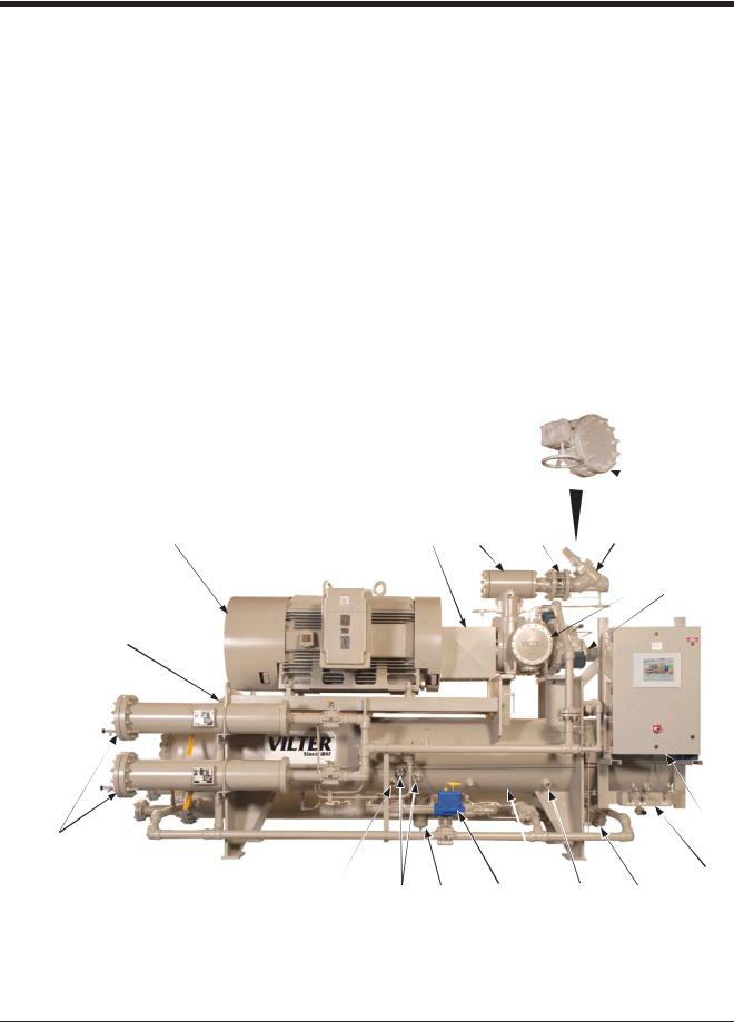
Compressor Unit Component Identification
Each gas compressor unit may differ, but below are typical components that can be found on each unit.
1 |
- Motor |
9 - Block & Bleed Assembly |
17 |
- Discharge Connection |
|
2 |
- Coupling |
10 |
- Oil Pump |
18 |
- Oil Separator Inspection Port |
3 |
- Suction Strainer |
11 |
- Oil Heater |
19 |
- Thermal/Acoustic Oil Separator |
4 |
- Suction Check Valve |
12 |
- Oil Separator |
|
Blanket |
|
|
||||
5a - Suction Stop Valve |
13 |
- Oil Temperature Control Valve |
|
(Optional Per Application) |
|
|
|
||||
5b - Suction Stop Butterfly Valve |
|
(Oil Mixing Valve) |
20 |
- Nameplate |
|
|
|
|
|
||
|
(Typically Shipped Loose) |
14 |
- Oil Pump Strainer |
21 |
- Heat Trace Insulation |
|
|
|
|
|
|
6 |
- Compressor |
15 |
- Oil Sight Glass |
|
(Optional Per Application) |
|
|
|
|
||
7 |
- Discharge Pipe |
16 |
- Oil Filter |
22 |
- Frame |
|
|
|
|
||
8 |
- PLC Panel |
|
(Optional Dual Oil Filters Shown) |
23 |
- Oil Cooler (Shell and Tube Heat |
|
|
|
Exchanger) |
||
|
|
|
|
|
|
 5b
5b
1 |
2 |
3 |
4 |
5a |
6 7
17
8
16
9
11 |
15 |
14 |
13 |
12 |
11 |
10 |
Figure 1-2. Gas Compressor Unit Components (1 of 3)
1 – 4 |
VSG/VSSG • Installation, Operation and Maintenance Manual •Vilter/Emerson • 35391SSG |
Section 1 • General Information
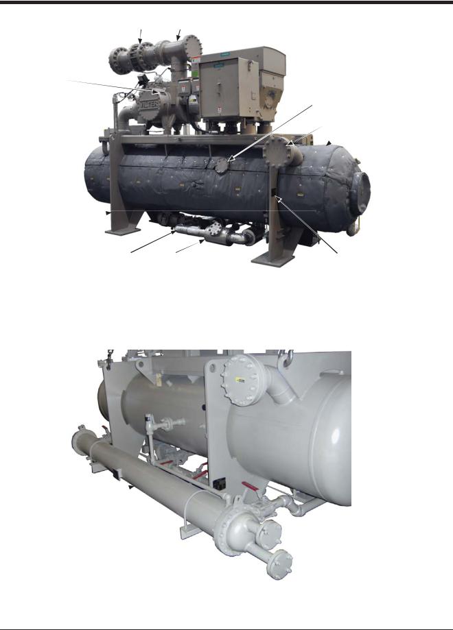
4 3
20
18 19
17
22
21 |
14 |
20 |
23
Figure 1-2. Gas Compressor Unit Components (2 of 3)
VSG/VSSG • Installation, Operation and Maintenance Manual •Vilter/Emerson • 35391SSG |
1 – 5 |
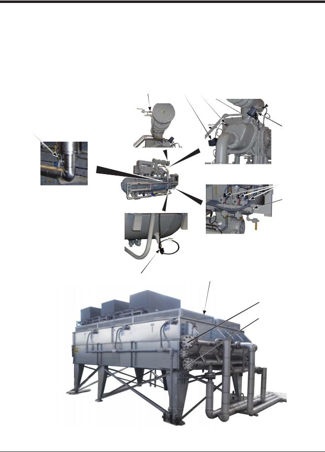
Section 1 • General Information
Component Identification (Continued)
24 |
- RTD (Oil Filter Outlet) |
28 |
- RTD (Suction) |
|
|
31 |
- Block & Bleed Assembly |
25 |
- Pressure Transducer (Oil Injection |
29 |
- Capacity Slide Valve Actuator |
32 |
- Remote Oil Cooler (Finned Fan |
||
|
Temperature) |
30 |
- Pressure Transducers |
|
|
Heat Exchanger) |
|
26 |
- Volume Slide Valve Actuator |
|
33 |
- RTD (Oil Separator) |
|||
|
(Discharge, Oil Filter Inlet and |
||||||
27 |
- RTD (Discharge) |
|
Outlet) |
|
|
|
|
|
|
|
|
|
|
||
|
|
|
25 |
26 |
27 |
|
28 |
|
24 |
|
|
|
|
|
29 |
|
|
|
|
|
|
|
30 |
|
|
|
|
|
|
|
31 |
33 |
32 |
OUTLET
INLET
Figure 1-2. Gas Compressor Unit Components (3 of 3)
1 – 6 |
VSG/VSSG • Installation, Operation and Maintenance Manual •Vilter/Emerson • 35391SSG |

Section 1 • General Information
Piping & Identification Component Tags
Use this list to identify components shown in the Piping & Identification Diagram.
A |
Atmosphere |
AN |
Anode - Sacrificial |
AV |
Angle Valve |
BFV |
Butterfly Valve |
BDV |
Automatic Blowdown |
|
Valve |
BV |
Ball Valve |
C |
Compressor |
CPL |
Coupling |
CRR |
Cooling Refrigerant Liquid |
|
Return |
CRS |
Cooling Refrigerant Liquid |
|
Supply |
CS |
Carbon Steel or Cold Side |
CV |
Check Valve |
CWR |
Cooling Water Return |
CWS |
Cooling Water Supply |
DDrive Motor or Drain
EHeat Exchanger
EQ |
Equalizing Line |
F |
Fan |
FC |
Fail Closed or Flow |
|
Controller |
FG |
Flow Switch Indicator or |
|
Glass |
FI |
Flow Indicator |
FIT |
Flow Indicating |
|
Transmitter |
FO |
Fail Open |
FSI |
Flow Sight Indicator |
FT |
Flow Transmitter (Blind) |
FV |
Flow Control Valve |
|
(Pneumatic Actuator) |
GLV |
Globe Valve |
GTV |
Gate Valve |
HS |
Hand Switch or Hot Side |
HEV |
Hand Expansion Valve |
HV |
Hand Valve |
IA |
Instrument Air |
II |
Current Indicator |
IT |
Current Transmitter |
JB |
Electrical Terminal Box or |
|
Junction Box |
LC |
Level Control |
LE |
Level Probe |
LI |
Level Indicator or Gauge |
LIT |
Liquid Level Indicating |
|
Transmitter |
LO |
Lube Oil or Lock Open |
LP |
Local Panel |
LSH |
Level Switch High |
LSHH |
Level Switch Shutdown |
|
High High |
LSL |
Level Switch Low |
LSLL |
Level Switch Shutdown |
|
Low Low |
LV |
Level Control Valve - |
|
Pneumatic Actuator |
MCC |
Motor Control Center or |
|
Motor Starter |
MV |
Motor Operated Valve |
MGV |
Manifold Gauge Valve |
MI |
Moisture Indicator |
N |
Nitrogen |
NC |
Normally Closed |
NO |
Normally Open |
NV |
Needle Valve |
P |
Pump or Process |
PDI |
Differential Pressure |
|
Indicator - Gauge |
PDIT |
Differential Pressure |
|
Indicating Transmitter |
PDSH |
Differential Pressure |
|
Switch High |
PDSHH Differential Pressure
|
Switch Shutdown High |
|
High |
PDSL |
Differential Pressure |
|
Switch Low |
PDSLL |
Differential Pressure |
|
Switch Shutdown Low |
|
Low |
PDT |
Differential Pressure |
|
Transmitter - Blind |
PDV |
Differential Pressure |
|
Control Valve - Pneumatic |
|
Actuator |
PI |
Pressure Indicator or |
|
Gauge |
PIT |
Pressure Indicating |
|
Transmitter |
PSH |
Pressure Switch High |
PSHH |
Pressure Switch |
|
Shutdown High High |
PSL |
Pressure Switch Low |
PSLL |
Pressure Switch |
|
Shutdown Low Low |
PSV |
Pressure Safety Relief |
|
Valve |
PT |
Pressure Transmitter |
|
- Blind |
PV |
Pressure Control Valve |
QE |
Heater Element - |
|
Immersion Heater |
R |
Refrigerant |
RD |
Rupture Disc |
SDV |
Automatic Shut-off Valve |
SG |
Sight Glass |
SSStainless Steel or Heat Exchanger Shell Side
STR |
Strainer |
SV |
Safety Relief or Slide Valve |
SW |
Selector Switch |
TE |
Temperature Element - |
|
RTD or Thermocouple |
VSG/VSSG • Installation, Operation and Maintenance Manual •Vilter/Emerson • 35391SSG |
1 – 7 |
Section 1 • General Information
TI |
Temperature Indicator or |
TW |
Thermowell |
YZT |
Axial proximitor |
|
Thermometer |
V |
Vent |
|
Transmitter - Axial |
|
|
|
Displacement |
||
TIT |
Temperature Indicator |
VG |
Gauge Valve |
|
|
|
|
||||
|
Transmitter |
YZU |
Axial Proximitor |
||
|
VTRI |
Venturi |
|||
TRV |
Transfer Valve - 3-way or |
|
Monitoring System |
||
|
|
|
|||
VLV |
Stop Valve |
|
|
||
|
6-way Valve |
ZE |
Position Element |
||
|
|
|
|||
TS |
Heat Exchanger Tube Side |
XV |
Solenoid Valve |
|
- Positioner |
|
|
|
|
||
TSH |
Temperature Switch High |
YE |
Vibration Probe |
ZI |
Position Indicator |
|
|
|
|
||
TSHH |
Temperature Switch |
YSH |
Vibration Switch High |
ZIT |
Position Indicating |
|
|
|
Transmitter |
||
|
Shutdown High High |
YSHH |
Vibration Switch |
|
|
|
ZT |
Position Transmitter |
|||
TTSL |
Temperature Switch Low |
|
Shutdown High High |
||
|
|
|
- Blind |
||
TSLL |
Temperature Switch |
YT |
Vibration Transmitter |
|
|
|
|
||||
|
|
|
|
||
|
Shutdown Low Low |
YU |
Vibration Monitoring |
|
|
TT |
Temperature Transmitter |
|
System |
|
|
|
|
|
|
||
|
- Blind |
YZE |
Axial Proximitor Probe - |
|
|
TV |
Temperature Control |
|
Axial Displacement |
|
|
|
|
|
|
||
|
Valve |
|
|
|
|
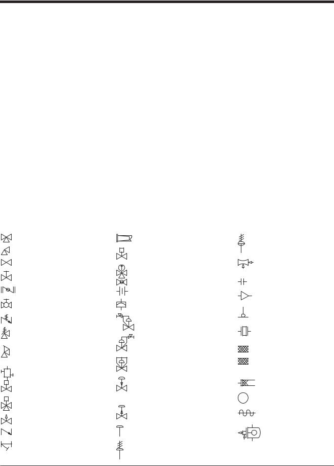
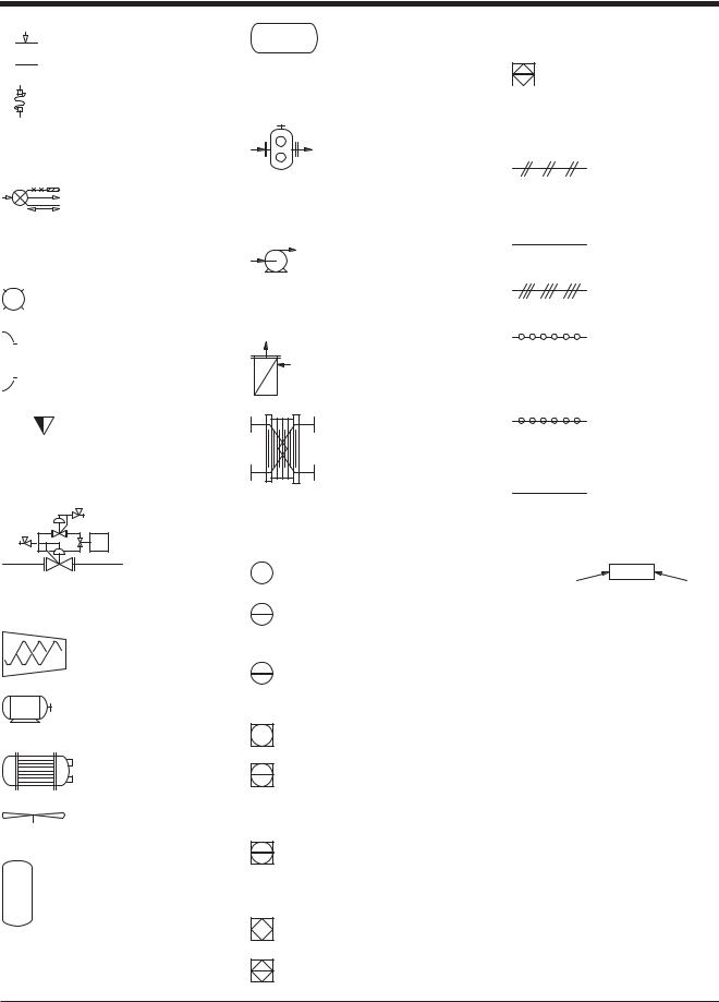
Symbols and Identifications
Use this list to identify components shown in the Piping & Identification Diagram.
3-Way Valve |
|
Suction Strainer |
|
Angle Valve |
M |
Motorized Valve |
|
|
|||
Globe Valve |
|
||
T |
3-Way Thermostatic Valve |
||
|
|||
Gate Valve |
|
Hand Expansion Valve |
|
Butterfly Valve |
|
Restriction Orifice |
|
Ball Valve |
|
Rupture Disc |
|
Schrader Valve |
|
Inlet Pressure Regulating |
|
Pressure Safety Relief |
|
Valve |
|
|
|
||
Valve |
|
Outlet Pressure |
|
Spring-Closing Drain |
|
Regulating Valve |
|
|
|
||
Valve |
|
Differential Pressure |
|
Block & Bleed Manifold |
|
Regulating Valve |
|
|
Pneumatic Actuator |
||
S |
|
||
|
Control Valve Fail Close |
||
Solenoid Valve |
|
||
|
|
||
S |
|
|
|
3-Way Solenoid Valve |
|
Pneumatic Actuator |
|
|
|
||
Needle Valve |
|
Control Valve Open |
|
|
|
||
Check Valve |
|
Diaphragm Actuator |
|
Strainer |
|
Diaphragm |
|
|
|
Spring-Opposed |
Diaphragm
Pressure-Balanced
Vilter Venturi Injector
Nozzle
Flange Set
Pipe Reducer
TW
Thermowell
Drive Coupling
CInsulation Not by Vilter
V
Insulation by Vilter


 Vibration Absorber
QE  Heater
Heat Trace
Low Side Float Valve
1 – 8 |
VSG/VSSG • Installation, Operation and Maintenance Manual •Vilter/Emerson • 35391SSG |
Section 1 • General Information


 High Side Float Valve
Steady-Mount


 Bulb & Capillary
Thermostatic Expansion
Valve
GPilot Light (Color Inside)


 MW Man-Way Cover
BYVILTER |
BY OTHERS |
|
|
Scope of Supply
SV
E1
Economizer Regulator
Compressor
Motor
Heat Exchanger
Fan
Vertical Tank/Drum Vessel
Horizontal Tank/Drum
Vessel
Positive Displacement
Pump
Centrifugal Pump


 Rotary Pump
Filter
Plate & Frame Heat
Exchanger
Discrete Instrument, Field Mounted
Discrete Instrument, Remote, Mount, Normally Accessible to Operator
Discrete Instrument, Local Rack Mounted, Normally Accessible to Operator
Shared Display/Control, Field Mounted
Shared Display/Control, DCS or Remote Control Panel Normally Accessible to Operator
Shared Display/Control, Local Control Panel Normally Accessible to Operator
Programmable Logic Control, Field Mounted
Programmable Logic Control, DCS or Remote
Control Panel, Normally
Accessible to Operator
Programmable Logic
Control, Local Control
Panel, Normally
Accessible to Operator
Pneumatic Signal
X X X X X |
Capillary Tube |
|
Electrical Signal |
Internal System Link (Software or Data Link)
Mechanical Link
L L L L L
Hydraulic Signal
EQUIPMENTTYPE |
V100 |
SERIES NUMBER |
Equipment Number
Identification
VSG/VSSG • Installation, Operation and Maintenance Manual •Vilter/Emerson • 35391SSG |
1 – 9 |

1 – 10 / Blank |
VSG/VSSG • Installation, Operation and Maintenance Manual •Vilter/Emerson • 35391SSG |

Section 2 • Theory of Operation
1 |
2 |
3 |
4 |
5 |
|
|
|
|
SUCTION GAS |
|
|
|
|
|
6 |
|
|
|
TE |
|
|
|
CHECK DISCHARGE |
|
|
|
|
|
|
|
VALVE |
STOP VALVE |
|
1/4” OIL CHARGING |
|
|
|
|
|
|
|
|
COMPRESSOR |
|
|
TE |
|
|
BLEED |
|
|
|
|
|
|
|
|
|
|
|
|
|
|
|
|
MOTOR |
|
|
|
|
1/4” |
|
|
|
|
|
|
|
|
|
|
|
|
|
14 |
13 |
|
|
|
|
BLEED |
|
|
|
|
|
15 |
|
|
|
|
|
OIL SEPARATOR |
|
|
|
|
|
|
|
|
|
|
|
TE |
|
12 |
|
|
|
|
|
|
|
|
|
|
|
FILTER |
|
|
|
|
11 |
|
|
|
|
STANDARD SINGLE |
TE |
|
|||
|
BLEED |
DRAIN |
|
||||
|
OIL FILTER |
|
100# |
|
|||
|
DRAIN |
|
|
MOTOR |
7 |
||
|
|
|
|
|
|
|
|
|
|
BLEED |
|
|
M |
|
|
|
|
|
|
|
FG |
|
|
|
|
|
|
|
|
|
|
|
|
|
|
|
|
1 |
|
|
|
|
|
|
|
PUMP |
|
FILTER |
DRAIN |
|
|
|
|
|
|
|
|
|
|
|
8 |
|
|
|
|
FILTER |
|
|
|
|
|
OPTIONAL DUAL OIL FILTERS |
DRAIN |
|
|
|
|||
|
|
|
|
||||
|
|
|
|
|
|
||
|
|
10 |
|
|
|
|
|
|
|
|
|
|
|
VENT |
|
|
|
|
|
|
|
OIL COOLER |
|
9
OIL |
|
|
|
|
DRAIN |
|
|
||||
DRAIN |
|
|
|||
|
|
|
|||
STANDARD WATER COOLED OIL COOLER
OPTIONAL REMOTE AIR COOLED OIL COOLER
Figure 2-1. Gas Compressor Unit P&ID
The gas and oil systems work in unison, but each one will be explained separately. Reference Figure 3 - Gas Compressor Unit P&ID for gas and oil flow descriptions.
Gas Flow
The gas compression process begins as processed gas enters the suction inlet (1). The processed gas flows through a stop valve (2), check valve (3) then through a suction line strainer (4) to the compressor (14). The processed gas is then pressurized through the compressor and discharged as high pressure gas vapor into the oil separator (13). In the oil separator, the oil is then separated from the discharged gas vapor by impingement separation. The high pressure gas flows out to
the aftercooler and scrubber for cooling while the oil is pumped or syphoned back to the compressor.
Moreover, check valves (3) and (6) are provided between the oil separator to prevent gas vapor or liquid from flowing back to the compressor during shutdown periods.
An equalizing line is also installed between the high pressure side (oil separator) and low pressure side (suc-
tion) to allow .
Oil Life and Oil Flow
The life of the oil is directly affected by the quality of the gas. Proper separation of any liquids must be accomplished to prevent droplets of liquid at the compressor
VSG/VSSG • Installation, Operation and Maintenance Manual •Vilter/Emerson • 35391SSG |
2 – 1 |

Section 2 • Theory of Operation
suction. The discharge temperature of the compressor must be kept a minimum of 30°F (or 17°C) above the discharge gas dew point to prevent the condensing of liquids in the oil separator. The oil separator shell and legs must be insulated when the gas stream has a high probability of having condensables.
Oil in the gas compressor unit serves three primary purposes. They are compressor lubrication, sealing clearances between moving parts, and heat removal resulting from heat of compression and friction. Initially, oil flow is driven by a mechanical gear pump (7). Once the system reaches design conditions, the oil pump is shut off and oil flow is maintained by differential pressure in the gas system.
As the oil is separated from the gas in the oil separator, it is pumped or syphoned through an oil cooler (9), then filtered through a single (11) or dual oil filters (15) and back to the injection port of the compressor (14). The standard oil cooler is a shell and tube water cooled heat exchanger (9). The other option is to air cool oil remotely through a finned fan heat exchanger (8).
Furthermore, to collect oil from the coalescing side of the oil separator (12), a line is installed between the oil separator and the compressor. By opening the shut-off valve (6), this will allow oil dripping off the coalescing filters to be fed back to the compressor. In addition, the oil cooler (8 or 9) is piped in parallel to the oil temperature control valve (oil mixing vlave) (10), which acts as a bypass valve.
On units with a full-time oil pump, oil pressure is regulated by the oil pressure regulator (12). It controls upstream pressure to the compressor bearings and should be adjusted to hold the oil pressure at 20 psig above suction pressure. Excess oil not required for bearing lubrication is passed through the regulator and back into the oil separator (13).
This is a continuous cycle.
RTDs and Pressure Transducers
Resistance Thermometers (RTDs) and pressure transducers are instruments used to measure temperatures and pressures at specific locations on the gas compressor unit, see Figure 1-2. Gas Compressor Unit Components. RTDs are typically mounted on the suction pipe, discharge pipe, oil separator and oil filter outlet pipe. Pressure transducers are typically mounted on the block and bleed assembly and directly on the suction pipe. The pressure transducers measure suction pressure, inlet and outlet oil pressure, and oil separator pressure.
Control System
The gas compressor unit is controlled by a Programmable Logic Controller (PLC) panel. This PLC panel’s main function is to control the gas compression system from the data that it receives from the sensors around the unit. Refer to Compact Logix PLC manual (35391CL) for additional information.
2 – 2 |
VSG/VSSG • Installation, Operation and Maintenance Manual •Vilter/Emerson • 35391SSG |
Section 3 • Installation
Delivery Inspection
All equipment supplied by Vilter are thoroughly inspected at the factory. However, damage can occur in shipment. For this reason, the units should be thoroughly inspected upon arrival, prior to off-loading. Any damage noted should be photographed and reported immediately to the transportation company. This way, an authorized agent can examine the unit, determine the extent of damage and take necessary steps to rectify the claim with no serious or costly delays. At the same time, the local Vilter representative or the home office should be notified of any claims made within ten (10) days after its discovery. Refer to long term storage for additional recommendations.
Rigging and Lifting of Compressor
Unit
WARNING
Whenriggingandliftingacompressorunit,useproper lifting device capable of lifting and maneuvering the weight and size of the compressor unit. Use only qualified personnel and additional personnel and lifting equipment (i.e. spreader bar) as required. Failure to comply may result in death, serious injury
and/or damage to equipment.
Only qualified personnel shall operate rigging and lifting equipment. Ensure that the lifting device is capable of lifting the weight of the compressor unit, refer to the supplied Vilter General Assembly (GA) drawing.
To lift the compressor unit, use lifting points on compressor unit frame to attach the lifting device, see Figure 3-1. There are a few points to consider prior to moving the unit:
•Ensure that the weight is evenly distributed amongst the lifting device (i.e. lifting chains and spreader bar) prior to lifting.
•Ensure that the lifting device is not obstructed by any parts of the compressor unit to prevent damage to components.
•Use additional personnel as needed to spot and aid in maneuvering the compressor unit.
•Ensure there is plenty of space to maneuver the compressor unit and a clear path to its location.
Lifting Point
Use lifting chains/straps and spreader bar. Evenly distribute weight. Keep lifting chains and spreader bar clear of components to prevent damage.
Figure 3-1. Rigging and Lifting Points
VSG/VSSG • Installation, Operation and Maintenance Manual •Vilter/Emerson • 35391SSG |
3 – 1 |

Section 3 • Installation
Long Term Storage Recommendations
The procedure described is a general recommendation for long term storage (over one month of no operation) of Vilter compressor units. It is the responsibility of the installation firm and end user to address any unusual conditions. Use the supplied long term storage log sheet to help with record keeping, see section page 3-3.
Warranty of the system remains in effect as described at the beginning of this manual, section page i.
The following are recommendations regarding long term storage:
COMPRESSOR MOTOR
The following are general recommendations. Refer to specific motor manufacturer instructions for storage recommendations.
•Remove the condensation drain plugs from those units equipped with them and insert silica-gel into the openings. Insert one-half pound bags of silicagel (or other desiccant material) into the air inlets and outlets of drip-proof type motors.
NOTE
Bags must remain visible and tagged, so they will be noticed and removed when the unit is prepared for service.
•If the unit is designed for indoor duty, it must be stored in a heated building.
•If the unit is designed for outdoor duty and is to be stored outdoors, a canvas tarp is recommended for protection until installation. Adequate drainage should be provided. Place wood blocks under the base skid so that water does not collect inside the base perimeter or low spots in the tarp.
•All compressor stop valves are to be closed to isolate the compressor from the remainder of the system. All other valves, except those venting to atmosphere, are to be open. The unit is shipped with dry nitrogen holding charge of approximately 5 psi above atmospheric pressure. It is essential that the nitrogen holding charge be maintained.
•The nitrogen or clean dry gas holding charge in the system and compressor are to be monitored on a regular basis for leakage. If not already installed, it is required that a gauge is to be added to help monitor the nitrogen holding charge pressure. If a drop in pressure occurs, the source of leakage must be found and corrected. The system must be evacuated and recharged with dry nitrogen to maintain the package integrity.
•Cover all bare metal surfaces (coupling, flange faces, etc.) with rust inhibitor.
•Desiccant is to be placed in the control panel. If the panel is equipped with a space heater, it is to be energized. Use an approved electrical spray-on corrosion inhibitor for panel components (relays, switches, etc.)
•All pneumatic controllers and valves (Fisher, Taylor, etc.) are to be covered with plastic bags and sealed with desiccant bags inside.
•Cover the motor completely to exclude dirt, dust, moisture, and other foreign materials.
•If the motor can be moved, it is suggested that the entire motor be encased in a strong, transparent plastic bag. Before sealing this bag, a moisture indicator should be attached to the side of the motor and several bags of silica-gel desiccant be placed inside the bag around the motor. When the moisture indicator shows that the desiccant has lost its effectiveness, replace desiccants.
•Whenever the motor cannot be sealed, space heaters must be installed to keep the motor at least 10°F above the ambient temperature.
•Rotate motor and compressor shafts several revolutions (approximately 6) per month to eliminate flat spots on the bearing surfaces. For motors utilizing anti-friction bearings, the shaft should be rotated once every 30 days by hand at 30 RPM for 15 seconds in each direction. Bearings should also be re-lubricat- ed at 2-year intervals using the grease specified on the motor lubrication nameplate.
•If the compressor unit is installed, wired and charged with oil, open all oil line valves and run the oil pump for 10 seconds prior to rotating the compressor shaft. Continue running the oil pump while the compressor shaft is being turned to help lubricate the surfaces of the shaft seal.
For additional storage information, refer to Appendices.
3 – 2 |
VSG/VSSG • Installation, Operation and Maintenance Manual •Vilter/Emerson • 35391SSG |

Section 3 • Installation
AIR COOLED OIL COOLERS
The following are general recommendations. Refer to specific air cooled oil cooler manufacturer instructions for storage recommendations.
•If the coolers are to be stored or not operated for an extended period of time, the fan motors may ingress moisture if they are not protected or operated regularly. In severe cases, the moisture will reduce the insulation level of the windings or cause rusting of the bearings necessitating removal for repairs at a motor repair facility. This is a common problem with large generating installations when the coolers are often ready but commissioning of the main turbine-gener- ator is delayed for several months.
•The simplest remedy for installed coolers is to operate the fan motors for a few hours every week during the downtime period until regular operation resumes. The fan motors on stored coolers must be protected from the elements by covering them with waterproof tarps.
Compressor Unit Inspections Prior to Storage or Installation
The compressor unit must be inspected prior to installation since components could have come loose and/or damaged during shipment or moving.
•Check for loose bolts, particularly the compressor and motor mounting nuts.
•Check for bent or damaged components. The compressor unit should have also been inspected prior to off-loading, see Delivery Inspection.
•Check that the nitrogen pressure is still holding pressure. The pressure gauge is located at the discharge bleed valve on the block and bleed assembly. Any leaks must be fixed and the system purged and recharged with dry nitrogen.
Recommended Onsite Tools
The tools recommended to have on site are important for troubleshooting, inspections and compressor unit operation. Besides general mechanic tools, these tools are recommended:
•Oil Pump (maximum of 2-3 GPM with motor approved for Division 1 or Division 2 and with ability to overcome suction pressure)
•Infrared Heat Gun
•Torque Wrenches (with ranges from 0 to 600 ft-lbs)
•Sockets and wrenches up to 2-1/2” (63.5 mm)
•Voltmeter
VSG/VSSG • Installation, Operation and Maintenance Manual •Vilter/Emerson • 35391SSG |
3 – 3 |

Section 3 • Installation
LONG TERM STORAGE LOG
Date: _______________________________
Name: _______________________________ Intial:_______________
Company:
Vilter Order No. _____________________________________________
Compressor Serial Number: ________________________________________________________
Was Compressor Shaft Rotated? |
_______YES |
_______ NO |
HOW OFTEN? __________ |
Was Air Cooled Oil Cooler Rotated? |
_______YES |
_______ NO |
HOW OFTEN? __________ |
Was Compressor Motor Rotated? |
_______YES |
_______ NO |
HOW OFTEN? __________ |
Was Compressor Motor Lubricated? |
_______YES |
_______ NO HOW OFTEN? __________ |
|
What was the Nitrogen pressure? |
_______PSIG |
|
|
Was it necessary to recharge with Nitrogen? |
________YES _______NO |
||
If unit needed recharging, was the leak found? |
________YES _______NO |
||
Please briefly explain nature of leak: |
|
|
|
Is compressor stored in a building that is heated and insulated to prevent condensation of moisture and freezing of Equipment?
___________YES _________NO
Are all machined surfaces exposed to atmosphere coated with a light grease to prevent rusting (compressor shaft)?
|
__________YES _________NO |
Compressor has been placed in operation as of: |
DATE ______________ |
3 – 4 |
VSG/VSSG • Installation, Operation and Maintenance Manual •Vilter/Emerson • 35391SSG |

Section 3 • Installation
Foundation |
Foundation Materials |
||
Materials needed to build the foundation are forms, |
|||
Vilter Single Screw compressor units are low vibra- |
|||
concrete, sand, rebar, wire, grout, anchor bolts, ex- |
|||
tion machines. Under most conditions, no elaborate |
|||
pansion board and shims. A set of concrete forms will |
|||
foundation is necessary. However a sound foundation |
|||
need to be acquired; generally, these can be rented or |
|||
maintains motor alignment and proper elevation, and |
|||
constructed from dimensional lumber. There should |
|||
is therefore required. Provided are recommendations |
|||
be enough 4,000 psi concrete with one inch aggregate |
|||
for the foundation and anchoring of the compressor |
|||
to build the foundation. Also, there should be enough |
|||
unit. The Vilter foundation supports the entire operating |
|||
sand to provide a base of compacted sand four inches |
|||
weight of the unit and is suitable for years of continuous |
|||
thick for the foundation to rest on, see Figure 1 - Con- |
|||
duty. Included are specifications for concrete, rebar, ag- |
|||
crete Pad with Compressor Unit Dimensions - Side |
|||
gregate, anchors and grout. |
|||
View. The rebar required is ASTM 615, grade 60, sizes |
|||
|
|
||
Considerations Prior to Starting |
#4 and #6. Wires will also be needed to tie the rebar |
||
together. The recommended grout is Masterflow 648CP |
|||
Consult professionals, such as building inspectors, |
high performance non-shirk grout to provide at least |
||
structural engineers, geotechnical engineers and/or |
a 1” thick pad under each foot. The recommended an- |
||
construction contractors prior to starting. Below are a |
chors are 5/8” Diameter HILTI HAS SS threaded rod for |
||
few points to consider: |
outdoor installations or HAS-E rods for indoor installa- |
||
|
|
tions. Anchor bolts shall have a five inch projection and |
|
Site Characteristics: |
12-3/8” embedment. The required adhesive is HIT-ICE/ |
||
• |
Soil information |
HIT/HY 150 anchoring system. There should be enough |
|
• |
Site drainage |
one inch expansion boards to go around the perimeter |
|
of the foundation. Finally there should be enough shim |
|||
• |
Wind data |
||
stock and extra anchor bolt nuts to level the compres- |
|||
• |
Seismic zone |
sor unit. |
|
|
|||
• |
Ingress and egress |
Building the Foundation |
|
• Power and power lines |
|||
Use the Vilter General Arrangement (GA) and founda- |
|||
|
|
||
|
|
tion drawings to help secure a building permit and |
|
Site Layout: |
foundation construction. The Vilter GA drawing will |
||
• Plant elevations, grading, drainage and erosion |
have the necessary dimensions required to determine |
||
• Accessibility to compressors for service |
the overall foundation size and where to locate the |
||
compressor unit on the foundation. It will also show the |
|||
• Location of surrounding buildings |
|||
dimensions required to form up the housekeeping piers |
|||
• Property lines and roadways |
that the compressor unit rests on. The Vilter foundation |
||
• |
Power |
drawing lists the necessary information to construct a |
|
suitable foundation. It includes the rebar requirements |
|||
• |
Fire safety |
||
and locations. It also shows anchor bolt locations, |
|||
|
|
grouting and the concrete specifications. Using the |
|
Safety: |
Vilter GA drawing, Vilter foundation drawing and the |
||
information from site characteristics, site layout and |
|||
|
NOTE |
||
|
safety studies will provide enough data to allow build- |
||
Always check with a safety engineer before proceeding. |
|||
ing the foundation to proceed. |
|||
|
|
||
• Arranging equipment with adequate access space for |
The foundation is to be cast and permanently exposed |
||
|
safe operation and maintenance |
||
|
against the earth. Therefore, if constructing on an exist- |
||
• |
Wherever possible, arrange equipment to be served |
||
ing floor, typically indoors, the floor will need to be bro- |
|||
|
by crane. If not feasible, consider other handling |
||
|
ken up to get to the earth. If starting from undisturbed |
||
|
methods |
||
|
soil, it must be also be prepared accordingly. In either |
||
|
|
||
• Make all valves and devices safely accessible |
case, these are some check points to consider: |
||
• Use special bright primary color schemes to differen- |
• Check the depth of your frost line to ensure |
||
|
tiate service lines |
||
|
the foundation extends below it |
||
• Lightening protection for outdoor installations |
|||
• Ensure the foundation rests entirely on natural rock |
|||
• |
Relief valve venting |
||
or entirely on solid earth, but never on a combination |
|||
VSG/VSSG • Installation, Operation and Maintenance Manual •Vilter/Emerson • 35391SSG |
3 – 5 |
Section 3 • Installation
of both
•Check the ability of the soil to carry the load
•Check wet season and dry season soil characteristics for static loading limits and elasticity
•Check local codes for Seismic Design requirements
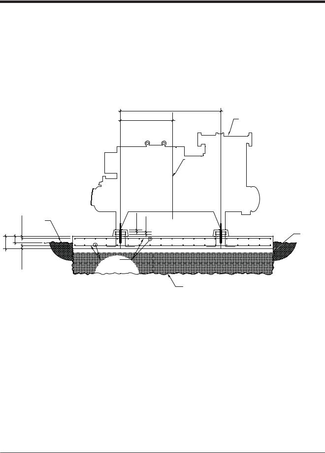
For examples of foundation diagrams, see to Figure 3-2 and Figure 3-3.
trolled level and a surface texture etched in place. Leave the concrete to cure for at least 28 days.
Compressor Unit Installation
Once the foundation has cured, the compressor unit can be placed on the foundation, see Figure 3-5 and Figure 3-6. With the appropriate material handling equipment, lift the compressor unit by locations shown on the Vilter GA drawing and slowly place it on the
G.A.
G.A. |
COMPRESSOR UNIT |
CENTER LINE OF
GAS COMPRESSION
SYSTEM
|
CLR. |
GRADE |
2"(TYP.) |
2"(TYP.) |
|
|
EL. TOP OF |
|
|
|
2" |
|
|
4" COMPACTED |
|
|
|
|
|
0" |
6" |
|
|
SAND |
|
|
|
||
1'- |
|
|
|
|
|
CLR. |
|
# 6 @ 12" |
|
|
|
EACH WAY |
|
|
|
3" |
|
|
|
|
|
TOP & BOTTOM |
|
|
|
|
|
|
|
|
|
|
|
EXCAVATE TO FROST DEPTH AS REQ'D AND BACKFILL |
|
|
|
|
WITH CLSM OR NON-FROST SUSCEPTIBLE FILL |
Figure 3-2. Concrete Pad with Compressor Unit Dimensions - Side View
NOTE
In Figures 3-3 and 3-8, the recommended housekeeping height of 6” is to allow maintenance/ service of the oil strainer and oil pump.
Once the site has been excavated and prepared, place four inches of sand down on the bed where the foundation will rest. The sand must be compacted before placing the forms and rebar. After the sand is compacted, use the Vilter GA drawing to construct the forms for the foundation. With forms in place, install expansion boards on the inside of the forms, for example, see Figure 3-4. Next, place your rebar in the forms as per the Vilter foundation drawing. When all rebars are in place the concrete can be poured. The concrete must then be
foundation housekeeping piers. As per the Vilter GA drawing, ensure the compressor unit is correctly placed on the foundation. Once placed, use the spherical washers directly under the compressor as the surface to level the compressor unit, see Figure 3-7. Place shims under the feet of the compressor unit, as needed, until it is leveled, see Figure 3-8. Select the correct drill bit and drill thru the anchor bolt hole in the mounting feet of the compressor unit to the depth called for on the Vilter foundation drawing. Finally using the HILTI instructions, put your anchor bolts in place and wait for them to cure. Then place the nuts on the anchor bolts to finger tight and prepare to grout.
3 – 6 |
VSG/VSSG • Installation, Operation and Maintenance Manual •Vilter/Emerson • 35391SSG |
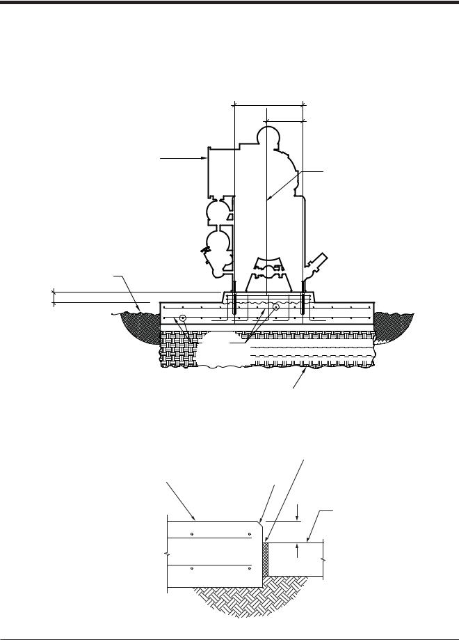
Section 3 • Installation
Leveling and Grouting |
recommendations for setting, precautions, mixing, and |
|
The unit should be level in all directions. Wet the |
grout placement, finishing and curing. The grout must |
|
be worked under all areas of the feet with no bubbles or |
||
concrete pad according to the grout manufacturer’s |
||
voids. If the grout is settled with a slight outside slope, |
||
directions. Mix a sufficient amount of grout. The grout |
||
oil and water can run off of the base. Once the grout has |
||
must be an expanding grout rather than shrinking to |
||
cured, torque the anchor bolts as per HILTI instructions. |
||
provide a tighter bond. Follow the manufacturer’s |
||
|
G.A.
G.A.
COMPRESSOR UNIT
CENTER LINE OF
GAS COMPRESSION
SYSTEM
EL. TOP OF
GRADE |
6" |
# 6 @ 12" 


 EACH WAY


 TOP & BOTTOM


EXCAVATE TO FROST DEPTH AS REQ'D AND BACKFILL
WITH CLSM OR NON-FROST SUSCEPTIBLE FILL
Figure 3-3. Concrete Pad with Compressor Unit Dimensions - Front View
|
|
|
|
|
|
ISOLATION JOINT, |
|
|
|
|
|
|
|
|
|
|
|
|
|
1" MINIMUM |
COMPRESSOR UNIT |
|
CHAMFER EDGE |
|
|
|
THICKNESS |
|
|
|||||
|
||||||
FOUNDATION |
|
|
|
|
|
|
CONCRETE SLAB IN
6” BUILDING
Figure 3-4. Interior Foundation Isolation
VSG/VSSG • Installation, Operation and Maintenance Manual •Vilter/Emerson • 35391SSG |
3 – 7 |
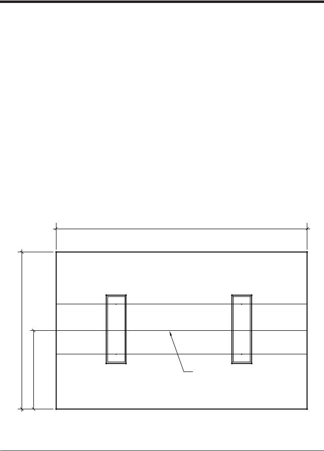
Section 3 • Installation
Additional Information
Codes and Standards
Vilter followed the following codes and standards when designing your foundation:
•ACI
•ASTM
•ASCE 7
•IBC 2006
General Design Requirements
The compressor foundation is designed to:
•Maintain the compressor in alignment and at proper elevation.
•Minimize vibration and prevents its transmission to other structures
•Provide a permanently rigid support
Operation and Performance |
• Provide sufficient depth to dampen vibrations. |
The foundation was designed for: |
|
•Outside environment severe exposure
•Ambient temperature -10 degrees F to 105 degrees F
•Unit weight 20,000 lbs
•RPM 3600
•Soil bearing capacity 1,500 lbs/sq.ft.
•Wind speed 120 MPH
•Exposure factor D
•Wind importance factor 1.15
•Concrete poured on and permanently cast against the earth
OVER ALL G.A. LENGTH + 4'-0"
10'-0"
5'-0"
CENTER LINE GAS COMPRESSION SYSTEM
Figure 3-5. Foundation with Housekeeping Pads Dimensions - Top View
3 – 8 |
VSG/VSSG • Installation, Operation and Maintenance Manual •Vilter/Emerson • 35391SSG |
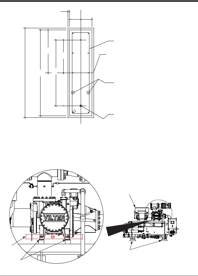
Section 3 • Installation |
|
||
|
|
1" (TYP.) |
|
|
|
G.A. |
G.A. |
|
|
|
(2) - # 4 |
|
|
G.A. |
CLOSED TIES |
|
|
CENTER LINE |
|
|
|
G.A. |
|
|
|
|
|
+ 2" |
G.A. |
G.A. |
|
G.A. |
|
|
(5) - # 6 VERT. |
|
|
|
|
|
|
|
WITH STD. 90° HOOK |
|
|
|
AT BOTTOM EACH |
|
|
|
FACE |
|
|
|
5/8" DIA. HILTI HAS SS THREADED ROD |
|
|
|
(HAS-E RODS ARE ACCEPTABLE FOR INTERIOR |
|
|
|
INSTALLATIONS) INSTALLED USING |
|
|
|
HIT-ICE/HIT-HY 150 ADHESIVE ANCHORING |
|
|
|
SYSTEM. |
|
|
|
(5" PROJECTION, 12 3/8" EMBEDMENT.) |
|
|
|
HOLES TO BE INSTALLED WITH HAMMER DRILL. |
|
|
|
DO NOT DIAMOND CORE. (TYP.) |
Figure 3-6. Housekeeping Pad Dimension Detail - Top View
LEVEL |
SPHERICAL |
WASHERS |
COMPRESSOR UNIT
HOUSEKEEPING PADS
Figure 3-7. Level Compressor Unit Using Top Surface of Spherical Washers
VSG/VSSG • Installation, Operation and Maintenance Manual •Vilter/Emerson • 35391SSG |
3 – 9 |
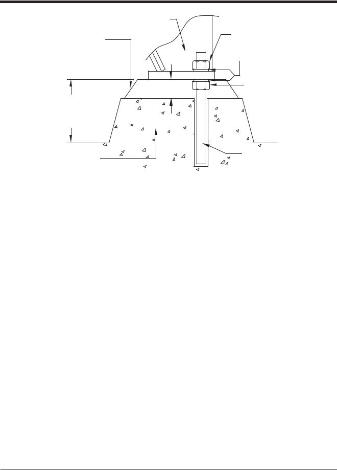
Section 3 • Installation |
|
|
70+6 .') |
010Ä5*4+0- |
*1.& &190 076 |
'21:; )4176 |
|
|
9#5*'4 |
|
.'8'.+0) 076 |
|
/+0 |
4'%1//'0&'& |
|
(14 |
|
*175'-''2+0) |
|
%10%4'6' |
#0%*14 $1.6 |
|
|
$#5' |
|
Figure 3-8. Concrete Pad Housekeeping Detail |
|
Piping
The ideal load applied to flanges of the compressor unit is zero. However, it’s not practical to expect that no loads will be applied to unit connections. Thermal, dead, live, wind & seismic loads must be considered and even tolerated. Well supported external piping connected to the compressor will still result in some loads applying forces and moments in three axes to unit flanges.
The most important issue is the motor-compressor misalignment caused by external forces (F in lbf) and moments (M in ft-lbf) imposed by plant piping. In Figure 3-9 and Table 3-2, are the maximum allowable forces and moments that can be applied to compressor flanges when the compressor is mounted on an oil separator.
It must be noted that it is necessary to check for compressor shaft movement when the job is complete. In no case shall the attached piping be allowed to cause more than 0.002” movement at the compressor shaft. If more than 0.002” movement is detected the piping must be adjusted to reduce the compressor shaft movement to less than 0.002”. For example, the compressor shaft should not move more than 0.002” when piping is removed or connected to the compressor.
IMPORTANT – piping elements shall be supported per the requirements of ASME B31.5 / B31.3 as applicable. See guidelines below, particularly with concern to minimizing loads on check valves.
Header Piping and Drains
Header drains should also be installed to allow drainage of liquids from the discharge and suction headers. See Appendices for Recommended Header Piping.
CAUTION
Accumulated liquid in the suction header can damage the compressor if not drained. Always drain headers (suction and discharge headers) prior to start-ups. Failure to comply may result in damage to equipment.
Remote Air Cooled Oil Cooler Piping
If equipped with a remote air cooled oil cooler, it is important that the piping be installed correctly to and from the compressor unit and remote air cooled oil cooler. See Appendices for Recommended Air Cooled Oil Cooler Piping.
3 – 10 |
VSG/VSSG • Installation, Operation and Maintenance Manual •Vilter/Emerson • 35391SSG |
 Loading...