


UVU-140A
UVU-140A AND UVU-140-AR
UNITIZED ULTRAVIOLET FIRE
DETECTOR
USER MANUAL
Part Number: MAN-0002-00 Rev. 1

Copyright © 2001 Net Safety Monitoring INC.
Printed in Canada
This manual is provided for informational purposes only. Although the information contained in this manual is
believed to be accurate, it could include technical inaccuracies or typographical errors. Changes are, therefore,
periodically made to the information within this document and incorporated without notice into subsequent revisions of
the manual. Net Safety Monitoring INC. assumes no responsibility for any errors that may be contained within this
manual.
This manual is a guide for the use of a Unitized UV Fire Detector and the data and procedures contained within this
document have been verified and are believed to be adequate for the intended use of the detector. If the detector or
procedures are used for purposes other than as described in the manual without receiving prior confirmation of validity
or suitability, Net Safety Monitoring Inc. does not guarantee the results and assumes no obligation or liability.
No part of this manual may be copied, disseminated or distributed without the express written consent of Net Safety
Monitoring Inc.
Net Safety Monitoring Inc. products, are carefully designed and manufactured from high quality components and can
be expected to provide many years of trouble free service. Each product is thoroughly tested, inspected and calibrated
prior to shipment. Failures can occur which are beyond the control of the manufacturer. Failures can be minimized by
adhering to the operating and maintenance instructions herein. Where the absolute greatest of reliability is required,
redundancy should be designed into the system.
Net Safety Monitoring Inc., warrants its sensors and detectors against defective parts and workmanship for a period of
24 months from date of purchase and other electronic assemblies for 36 months from date of purchase.
No other warranties or liability, expressed or implied, will be honoured by Net Safety Monitoring INC
Contact Net Safety Monitoring Inc. or an authorized distributor for details.

TABLE of CONTENTS
CHAPTER 1 TECHNICAL INFORMATION .......................................1
Introduction................................................................................ 1
Features .................................................................................. 1
Spectral Sensitivity Range .................................................................... 1
Figure 1 - Various Spectral Distributions ............................................... 1
Speci fications .............................................................................. 2
Applications ............................................................................... 3
CHAPTER 2 INSTALLATION .................................................4
What’s in the package .....................................................................4
Mounting the Detector .......................................................................4
Cone of vision ....................................................................... 4
Figure 2 - Detector cone of vision ..................................................... 4
Range ............................................................................. 4
Environmental Factors ................................................................ 4
False Alarms ........................................................................5
Position and Density of Detectors ........................................................ 5
Figure 3 - Detector with Swivel Mount .................................................. 6
Figure 4 - Detector Dimensions ........................................................7
Figure 5 - Swivel Mount Dimensions ................................................... 7
Figure 6 - JB4-UV-T Junction Box Side View ............................................. 7
Figure 7 - JB4-UV-T Junction Box Top View ............................................. 7
General Wiring Requirements ................................................................. 8
Wiring Diagram for UVU-140-A ..........................................................9
Figure 8 - Wiring for UVU-140-A ........................................................ 9
Wiring Diagram for UVU- 140-AR ....................................................... 10
Figure 9 - Wiring for UVU-140-AR .....................................................10
Detector Settings .......................................................................... 11
System Sensitivity ................................................................... 11
Figure 10 - DIP switch operation and location ........................................... 11
Table 1 - Detector Sensitivity Settings ................................................... 11
System Time Delay .................................................................. 11
Table 2 - Alarm Response Delay Settings ................................................ 11
Table 3 - Coil and Relay Status ........................................................ 12
CHAPTER 3 START UP AND TEST ...........................................12
Start up Procedure ......................................................................... 12
Check Out Procedure ................................................................ 12
Automatic vi Test.................................................................... 12
Test Procedures: .................................................................... 13
Manual Check Procedure ....................................................................13
CHAPTER 4 NORMAL OPERATION...........................................14
Normal Operation ......................................................................... 14
Fire Condition .............................................................................14
Current & Relay Output Conditions ............................................................ 14
Table 4 - Current & Relay Output Conditions .............................................. 14
CHAPTER 5 MAINTENANCE ................................................15
Routine Maintenance ....................................................................... 15
Troubleshooting ..................... ............... .................. ............... ...... 15
Cleaning Viewing Window and Reflector ................................................. 15
Repositioning vi Adjustment Allen Screw ................................................. 15
Device Repair and Return ................................................................... 16

Appendix A Net Safety Monitoring Inc. Electrostatic Sensitive Device Handling
Procedure ...............................................................17
Appendix B Common Ultra-Violet Absorbing Gases . . . . . . . . . . . . . . . . . . . . . . . . . . . . . 18
Appendix C Wire Resistance In Ohms ........................................19
CHAPTER 1 TECHNICAL INFORMATION
Introduction
The UVU-140-A & UVU-140-AR fire detectors provide fast, reliable flame detection in a wide variety of
applications. The automatic visual integrity (vi) feature allows for a continuous check of optical surfaces,
sensitivity and electronic circuitry of the unitized fire detector. Fire and fault identification are accomplished by
the use of specific current output levels and relay contacts (UVU-140-AR only). The fire detectors are housed in
explosion-proof enclosures that are designed to meet most national and international standards. They are
available in anodized aluminum or optional stainless steel. The UVU-140-A & UVU-140-AR fire detectors are
typically mounted with a swivel mounting assembly (see Figure 3).
The UVU-140-AR unitized fire detector connects to a JBR-T-ASSY which consists of a junction box, two relays
and a terminal connector board. The JBR-T-ASSY has large, easy access, spring tension terminals and a user
selectable dip switch which allows the operator to select relay and coil status conditions (see Table 3).
Features
< Instantaneous response to ultraviolet radiation
< Automatic and manual visual integrity (vi) testing
< Adjustable sensitivity and time delay
< All automatic test functions are performed with the system on-line
< Alarm and automatic fault identification indicated by a 4 to 20mA output
< Relay outputs for fire and fault identification (UVU-140-AR only)
< The fault relay is normally energized and non-latching (UVU-140-AR only)
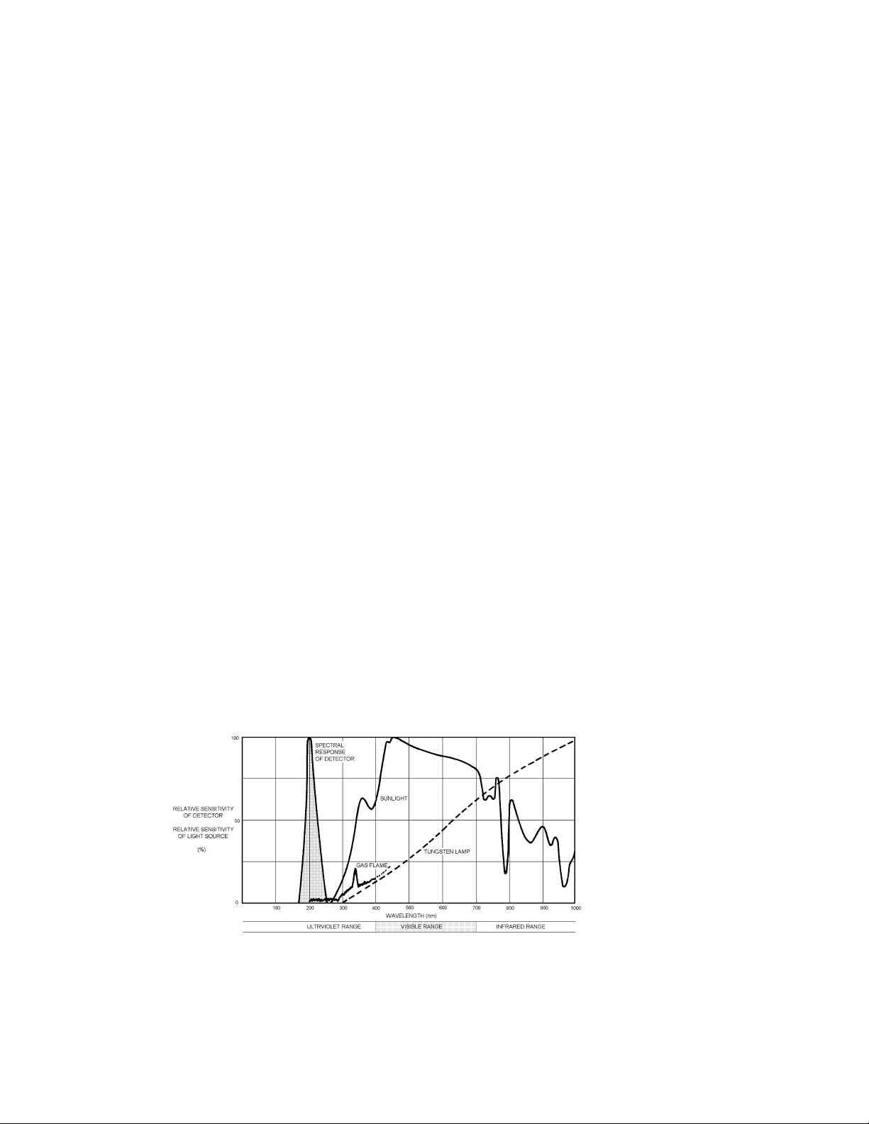
Spectral Sensitivity Range
The UVU-140-A & UVU-140-AR fire detectors respond to radiation wavelengths of 185 to 260 nanometres
(1850 to 2600 angstroms). Figure 1 illustrates the range of sensitivity and compares this range to other forms of
radiation. Note that UV radiation reaching the earth from the sun does not extend into the sensitivity range of the
detector. Nor does radiation from normal artificial lighting, such as fluorescent, mercury vapour and incandescent
lamps.
Figure 1 - Various Spectral Distributions
1

Specifications
< Operating Voltage Range:
24Vdc nominal: 10.5 to 32Vdc
If a fuse is rated in line with the main power supply, it should be a 1A slow-blow type. If a power
supply with current limiting is used it should have a rating appropriate for the inrush current
required by the product.
< Power Consumption (UVU-140-A):
1.92 Watts nominal 2.4 Watts maximum @ 24Vdc
80mA nominal 100mA maximum @ 24Vdc
Inrush Current 250 mA for 2.5 ms
< Power Consumption (UVU-140-AR):
2.4 Watts nominal (fault relay energized) @ 24Vdc
2.9 Watts maximum (fire & fault relays energized) @ 24Vdc
100mA nominal @ 24Vdc 120mA maximum @ 24Vdc
Inrush Current 380 mA for 2.5 ms
< Temperature Range:
Operating: -40ºC to +85ºC (-40/F to +185/F)
Storage: -55ºC to +125ºC (-67/F to +257/F)
< Dimensions:
Refer to Figures 4, 5, 6 and 7
< Detector Enclosure Materials:
NEMA 4X anodized copper-free aluminum or stainless steel (optional)
< Shipping Weight (approximate):
2 lbs (0.9 kilograms) aluminum
< Certification:
CSA, NRTL/C, NEMA 4X certified for hazardous locations
Class 1, Division 1, Groups B, C and D
IEC approval Ex d IIB+H2 T5 (Class 1, Zone 1, Groups IIB+H2 T5)
< Spectral Sensitivity Range:
The detectors respond to UV radiation over the range of 185 to 260 nanometres
(1850 to 2600 angstroms)
< Cone of Vision:
120 degree cone of vision when measured in accordance with NFPA 72 guidelines
< Current Outputs:
4-20mA DC into a maximum external loop resistance of 600 Ohms at 10.5 to 32Vdc
2
< Relay Contacts: (Available on UVU-140-AR only)

1A @ 30Vdc 0.5A @ 125Vac
< Response Time:
Response to a saturating (high intensity) UV source is typically 10 milliseconds
Alarm response time is programmable
< Time Delay Settings:
DIP switch selectable 3, 4, 5 or 7 seconds
< Sensitivity Settings:
DIP switch selectable 8, 16, 24 or 32 counts per second
< Humidity Range:
0 to 100% relative humidity
Applications
The UVU-140-A & UVU-140-AR fire detectors respond instantly to ultraviolet radiation emitted by a flame.
These devices are designed for use in hazardous locations and are suitable for use in outdoor applications.
Typical applications for UV detection systems
< around highly combustible materials
< when instantaneous response to flame is needed or where automated fire protection is required
< protection of large capital investments
Petroleum Products Handling
< petroleum loading terminals
< offshore platforms
< pipeline stations
< tank farms
< refineries
< engine rooms
Gaseous Fuel Handling
< butane and propane loading and storage
< pipeline compressor stations
< gas gathering facilities
< LNG loading, transfer and storage
< hydrogen
< gas turbines
Other Processes
< paint spray booths
< chemical and petrochemical production
< powder coating booths
Automated fire protection systems also have applications in any manufacturing or research facility where the
potential of fire may be low to moderate, but the losses due to a fire would be high.
3
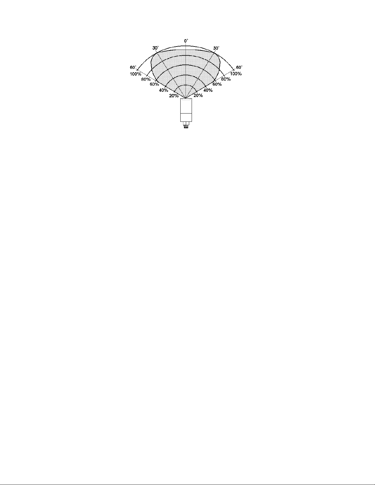
Figure 2 - Detector cone of vision
CHAPTER 2 INSTALLATION
What’s in the package
Remove all the components from the packing box(s) carefully; check components against the packing list. Inspect
all components for obvious damage and broken/loose parts. Notify the carrier and distributor immediately if
damage is found or parts are missing.
Mounting the Detector
There are many factors that you should be aware of when positioning your fire detector(s).
Cone of vision
The UVU-140-A & UVU-140-AR fire detectors have a nominal 120 degree cone of vision when measured in
accordance to NFPA 72 guidelines. Figure 2 shows the cone of vision and detector response to a UV source at
various distances.
Range
The practical application distance is up to about 80 feet (25 metres). The distance is directly related to the
intensity of the ultraviolet radiation source. Programming the UVU-140-A & UVU-140-AR fire detectors to
require a high count rate results in low system sensitivity.
Environmental Factors
Airborne contamination such as steam , oil mist, ice build up and smoke can impair the detection capabilities of
UV fire detectors and should be avoided.
Since the UVU -140-A & UVU-140-AR fire detectors are designed to detect fires by responding to the ultraviolet (UV) radiation they emit, it is very important to be aware of UV absorbing gases that may be present
4
 Loading...