


Instruction Manual
IB-106-300NH Rev. 4.3
May 2005
World Class 3000
Oxygen Analyzer
with IFT 3000 Intelligent Field Transmitter
http://www.raihome.com

ESSENTIAL INSTRUCTIONS
READ THIS PAGE BEFORE PROCEEDING!
Rosemount Analytical designs, manufactures and tests its products to meet many national and international standards. Because these instruments are sophisticated technical products, you MUST properly install, use, and maintain them to ensure they continue to operate within their normal specifications. The following instructions MUST be adhered to and integrated into your safety program when installing, using, and maintaining Rosemount Analytical products. Failure to follow the proper instructions may cause any one of the following situations to occur: Loss of life; personal injury; property damage; damage to this instrument; and warranty invalidation.
•Read all instructions prior to installing, operating, and servicing the product.
•If you do not understand any of the instructions, contact your Rosemount Analytical representative for clarification.
•Follow all warnings, cautions, and instructions marked on and supplied with the product.
•Inform and educate your personnel in the proper installation, operation, and maintenance of the product.
•Install your equipment as specified in the Installation Instructions of the appropriate Instruction Manual and per applicable local and national codes. Connect all products to the proper electrical and pressure sources.
•To ensure proper performance, use qualified personnel to install, operate, update, program, and maintain the product.
•When replacement parts are required, ensure that qualified people use replacement parts specified by Rosemount Analytical. Unauthorized parts and procedures can affect the product’s performance, place the safe operation of your process at risk, and VOID YOUR WARRANTY. Look-alike substitutions may result in fire, electrical hazards, or improper operation.
•Ensure that all equipment doors are closed and protective covers are in place, except when maintenance is being performed by qualified persons, to prevent electrical shock and personal injury.
If a Model 275/375 Universal HART® Communicator is used with this unit, the software within the Model 275/375 communicator may require modification. If a software modification is required, please contact your local Fisher-Rosemount Service Group or National Response Center at 1-800-654-7768.
The information contained in this document is subject to change without notice.
Emerson Process Management
Rosemount Analytical Inc. Process Analytic Division
6565P Davis Industrial Parkway Solon, OH 44139
T (440) 914 1261
F (440) 914 1271
E gas.csc@emersonprocess.com
http://www.raihome.com
|
HIGHLIGHTS OF CHANGES |
|
Effective May, 1999 Rev. 4.0 |
|
|
Page |
Summary |
|
|
Page P-6 |
Added new Quick Start Guide. |
Page 3-1 |
Added Section 3, Setup. |
Page 4-1 |
Removed calibration information from Operation section, and created |
|
Section 4, Calibration. |
Page 6-2 |
Expanded explanations of IFT status codes. |
Section 6 |
Added new troubleshooting procedures. |
|
|
|
Effective November, 2001 Rev. 4.1 |
|
|
Page |
Summary |
Highlights |
Updated Highlights of Changes Appendix A page. |
Appendix A |
Replaced Appendix A, Rev. 3.6 with Rev. 3.7. |
|
|
|
Effective November, 2001 Rev. 4.2 |
|
|
Page |
Summary |
|
|
Highlights |
Updated Highlights of Changes Appendix A page. |
Page 4-1 |
Added reference to new Calibration Record sheet. |
Page 4-9 |
Added new Calibration Record sheet. |
Appendix A |
Replaced Appendix A, Rev. 3.7 with Rev. 3.8. |
|
|
HIGHLIGHTS OF CHANGES (CONTINUED)
|
Effective May, 2005 Rev. 4.3 |
Page |
Summary |
|
|
Highlights |
Updated Highlights of Changes Appendix A, B, D, E, J pages. |
--- |
Changed “Rosemount” to “Rosemount Analytical”. |
P-8 |
Revised Figure 2. |
1-1 |
Revised Figure 1-1. |
1-6 |
Revised Figure 1-3. |
2-5, 2-6 |
Revised Figure 2-1, sheets 1 and 2. |
2-9 |
Revised Figure 2-4. |
2-13 |
Revised Figure 2-8. |
2-14 |
Revised Figure 2-9. |
2-15 |
Revised Figure 2-10. |
2-18, 2-19 |
Revised Figure 2-14, sheets 1 and 2. |
2-22 |
Revised Figure 2-18. |
2-24 |
Revised Figure 2-20. |
4-4 |
Revised Figure 4-1. |
4-6 |
Revised Figure 4-3. |
4-7 |
Revised Figure 4-4. |
5-2 |
Revised Figure 5-1. |
7-1 |
Changed RMR facility address. |
Appendix A |
Replaced Appendix A, Rev. 3.8 with Rev. 3.9. |
Appendix B |
Replaced Appendix B, Rev. 2.2 with Rev. 2.3. |
Appendix D |
Replaced Appendix D, Rev. 2.4 with Rev. 2.5. |
Appendix E |
Replaced Appendix E, Rev. 4.5 with Rev. 4.6. |
Appendix J |
Replaced Appendix J, Rev. 1.1 with Rev. 1.2. |
Back cover |
Changed Rosemount Analytical address. |
|
|
|
HIGHLIGHTS OF CHANGES |
|
APPENDIX A |
|
Effective May, 1996 Rev. 3 |
|
|
Page |
Summary |
|
|
--- |
General. Updated appendix to reflect probe design changes. |
Page A-13 |
Added “Extended temperature by-pass arrangements” to Figure A-13 |
|
(Sheet 3 of 3) |
|
|
|
Effective June, 1996 Rev. 3.1 |
|
|
Page |
Summary |
|
|
Page A-13 |
Updated part ordering information. |
|
|
|
Effective August, 1996 Rev. 3.2 |
|
|
Page |
Summary |
|
|
Page A-25 |
Updated cell replacement kit part numbers for the probe. |
|
|
|
Effective October, 1996 Rev. 3.3 |
|
|
Page |
Summary |
|
|
Page A-6 |
Added NOTE to Figure A-7. |
|
|
|
Effective January, 1997 Rev. 3.4 |
|
|
Page |
Summary |
Page A-1 |
Added warning to read new safety instructions. |
Page A-12 |
Added protective covers and grounds warning. |
Page A-16 |
Added protective covers and grounds warning. |
|
|
|
Effective February, 1998 Rev. 3.5 |
|
|
Page |
Summary |
|
|
Page A-18 |
Changed screw torque in paragraph A-11h. |
|
|
|
Effective July, 1998 Rev. 3.6 |
|
|
Page |
Summary |
|
|
--- |
Changed test gas to calibration gas and reference gas to reference |
|
air throughout the appendix. |
|
HIGHLIGHTS OF CHANGES (CONTINUED) |
|
Effective November, 2001 Rev. 3.7 |
|
|
Page |
Summary |
|
|
A-8 |
Added new cup type diffusion assembly description, paragraph A-6.e. |
|
and diffusion assembly illustrations, Figure A-13 and A-14. |
A-26 |
Added new cup type diffusion assembly part numbers 4851B89G04 |
|
and 4851B90G04 to replacement parts list. Deleted stainless steel |
|
diffuser assembly from replacement parts list. |
|
Effective July, 2002 Rev. 3.8 |
|
|
Page |
Summary |
|
|
A-13 |
Added troubleshooting symptoms 5 and 6 to Table A-2. |
|
|
|
Effective May, 2005 Rev. 3.9 |
|
|
Page |
Summary |
|
|
--- |
Changed “Rosemount” to “Rosemount Analytical”. |
|
|
|
HIGHLIGHTS OF CHANGES |
|
APPENDIX B |
|
Effective February, 1992 Rev. 2 |
|
|
Page |
Summary |
|
|
Page B-1 |
Figure B-1. New HPS 3000 Optional Class 1, Division 1, Group B |
|
(IP56) Explosion-Proof Enclosure added. |
Page B-11 |
Figure and Index No. column added to Table B-2. Replacement Parts |
|
for Heater Power Supply. |
|
Effective January, 1995 Rev. 2.1 |
|
|
Page |
Summary |
|
|
Page B-3 |
Updated Figure B-3, Heater Power Supply Block Diagram for IB |
|
consistency. |
|
Effective January, 1997 Rev. 2.2 |
|
|
Page |
Summary |
Page B-1 |
Added warning to read new safety instructions. |
Page B-3 |
Corrected Table B-1 specifications list. |
Page B-4 |
Added protective covers and grounds warning. |
Page B-8 |
Added protective covers and grounds warning. |
Page B-11 |
Added expanded fuse description. |
|
|
|
Effective May, 2005 Rev. 2.3 |
|
|
Page |
Summary |
|
|
--- |
Changed “Rosemount” to “Rosemount Analytical”. |
|
|
|
HIGHLIGHTS OF CHANGES |
|
APPENDIX D |
|
Effective June, 1994 Rev. 2 |
|
|
Page |
Summary |
|
|
Page D-1 |
MPS outline drawing changed to show new MPS. |
Page D-2 |
MPS interior view replaced with new MPS in Figure D-2. |
Page D-3 |
"Optional" for check valve deleted in Figure D-3. |
Page D-4 |
Drawing showing location of optional Z-Purge added as Figure D-4. |
Page D-7 |
Power supply replacement procedures in paragraph D-7 changed to |
|
reflect new design in the MPS. Solenoid valve replacement proce- |
|
dures in paragraph D-8 changed to reflect new design in the MPS. |
Page D-8 |
Old exploded view of MPS replaced with new MPS. |
Page D-10 |
Paragraph D-11, Adding Probes to the new MPS, added. |
Page D-11 |
Change part numbers for the power supply, solenoid valve, and test |
|
gas flowmeter assembly. Add part numbers for reference gas flow- |
|
meter assembly and all the parts in the probe adder kit. |
|
Effective January, 1995 Rev. 2.1 |
|
|
Page |
Summary |
|
|
Page D-1 |
Updated Figure D-1, MPS 3000 to include hinge. |
|
|
|
Effective May, 1996 Rev. 2.2 |
|
|
Page |
Summary |
|
|
Page D-11 |
Updated replacement parts list to reflect new part numbers. |
|
|
|
Effective January, 1997 Rev. 2.3 |
|
|
Page |
Summary |
|
|
Page D-1 |
Added warning to read new safety instructions. |
Page D-2 |
Corrected Table D-1 Specifications listing, 1st entry. |
Page D-5 |
Added protective covers and grounds warning. |
Page D-7 |
Added protective covers and grounds warning, corrected item num- |
|
ber errors in paragraph D-6. |
Page D-11 |
Added expanded fuse descriptions. |
|
|
|
HIGHLIGHTS OF CHANGES (CONTINUED) |
|
Effective July, 1998 Rev. 2.4 |
|
|
Page |
Summary |
|
|
--- |
Changed test gas to calibration gas and reference gas to reference |
|
air throughout the appendix. |
|
|
|
Effective May, 2005 Rev. 2.5 |
|
|
Page |
Summary |
|
|
--- |
Changed “Rosemount” to “Rosemount Analytical”. |
D-3 |
Revised view of check valve in Figure D-3. |
|
|
|
HIGHLIGHTS OF CHANGES |
|
APPENDIX E |
|
Effective May, 1996 Rev. 4 |
|
|
Page |
Summary |
|
|
--- |
General. Updated text and illustrations to reflect new version of IFT. |
Page E-4 |
Updated IFT display status codes and placed in priority sequence. |
|
|
|
Effective June, 1996 Rev. 4.1 |
|
|
Page |
Summary |
|
|
Page E-2 |
Updated specification table. |
|
|
|
Effective October, 1996 Rev. 4.2 |
|
|
Page |
Summary |
Page E-4 |
Added new status displays for password protection features. |
|
|
|
Effective January, 1997 Rev. 4.3 |
|
|
Page |
Summary |
Front matter |
Added "Safety instructions for the wiring and installation of this |
|
apparatus.” |
Page E-1 |
Added warning to read new safety instructions. |
Page E-2 |
Deleted NOTE. |
Page E-4 |
Added protective covers and grounds warning. |
Page E-8 |
Added protective covers and grounds warning. |
Page E-15 |
Added expanded fuse description. |
|
|
|
Effective July, 1998 Rev. 4.4 |
|
|
Page |
Summary |
--- |
Changed test gas to calibration gas throughout the appendix. |
|
|
|
Effective June, 1999 Rev. 4.5 |
|
|
Page |
Summary |
Page E-1 |
Changed “real time clock” to “timer”. |
|
|
--- |
Changed test gas to calibration gas and reference gas to reference |
|
air throughout the appendix. |
HIGHLIGHTS OF CHANGES (CONTINUED)
|
Effective May, 2005 Rev. 4.6 |
Page |
Summary |
|
|
--- |
Changed “Rosemount” to “Rosemount Analytical”. Changed views of |
|
IFT 3000 enclosure. Named GUI/LED display standard (not optional). |
E-2 |
Revised Electrical Noise specifications. |
E-8 through E-16 |
Changed all service instructions to reflect new IFT 3000 assembly con- |
|
figuration. Revised replacement parts list. |
|
HIGHLIGHTS OF CHANGES |
|
APPENDIX J |
|
Effective April, 1995 Rev. 1 |
|
|
Page |
Summary |
|
|
Page J-13 |
Added statement of reference to the return authorization number. |
|
|
|
Effective June, 1995 Rev. 1.1 |
|
|
Page |
Summary |
|
|
--- |
Figure J-4. Updated figure to include “Status group” and “K3 eff” in |
|
calculations. |
|
Effective May, 2005 Rev. 1.2 |
|
|
Page |
Summary |
J-1 |
Revised Figure J-1 to show Model 375 Communicator. |
|
|
J-3, J5 |
Revised Figure J-2 and J-3 to show location of new microprocessor |
|
board switches. |
J-13 |
Revised RMR facility address. |
|
|

World Class 3000
Instruction Manual
IB-106-300NH Rev. 4.3
May 2005
|
|
|
|
TABLE OF CONTENTS |
|
|
|
PREFACE........................................................................................................................ |
|
|
|
P-1 |
|
|
Definitions........................................................................................................................ |
|
|
|
P-1 |
|
|
Safety |
Instructions .......................................................................................................... |
|
P-2 |
||
|
Glossary of Terms ......................................................................................................... |
|
P-3 |
|||
|
Quick Start |
Guide .......................................................................................................... |
|
P-6 |
||
1-0 |
DESCRIPTION AND SPECIFICATIONS...................................................................... |
1-1 |
||||
1-1 |
Component Checklist of Typical System (Package Contents).................................. |
1-1 |
||||
1-2 |
System Overview............................................................................................................ |
|
1-2 |
|||
2-0 |
INSTALLATION .............................................................................................................. |
|
2-1 |
|||
2-1 |
Oxygen Analyzer (Probe) Installation........................................................................... |
2-1 |
||||
2-2 |
Intelligent Field Transmitter (IFT) Installation .............................................................. |
2-9 |
||||
2-3 |
Heater |
Power Supply |
Installation ............................................................................... |
2-13 |
||
2-4 |
Multiprobe |
Calibration |
Gas Sequencer Installation .................................................. |
2-21 |
||
3-0 |
SETUP |
............................................................................................................................. |
|
|
|
3-1 |
3-1 |
Overview.......................................................................................................................... |
|
|
|
3-1 |
|
3-2 |
Configuring |
the |
Analog Output ..................................................................................... |
3-1 |
||
3-3 |
Setting |
Calibration Parameters ...................................................................................... |
3-1 |
|||
3-4 |
Setting the O2 Alarm Setpoints.................................................................................... |
3-2 |
||||
3-5 |
Configuring |
Efficiency |
Calculations ............................................................................... |
3-2 |
||
3-6 |
Configuring |
the |
Relay |
Outputs ..................................................................................... |
3-2 |
|
4-0 |
CALIBRATION................................................................................................................ |
|
|
4-1 |
||
4-1 |
Analog |
Output |
Calibration ............................................................................................. |
4-1 |
||
4-2 |
System |
Calibration ......................................................................................................... |
|
4-1 |
||
5-0 |
GENERAL USER INTERFACE (GUI) OPERATION.................................................. |
5-1 |
||||
5-1 |
Overview.......................................................................................................................... |
|
|
|
5-1 |
|
5-2 |
Deluxe Version IFT Displays and Controls................................................................. |
5-2 |
||||
5-3 |
Help Key ......................................................................................................................... |
|
|
|
5-3 |
|
5-4 |
Status |
Line...................................................................................................................... |
|
|
5-3 |
|
5-5 |
Quick Reference Chart .................................................................................................. |
5-3 |
||||
5-6 |
Main Menu |
...................................................................................................................... |
|
|
5-3 |
|
5-7 |
Probe Data Sub-Menu |
................................................................................................... |
5-3 |
|||
5-8 |
Calibrate O2 Sub-Menu ................................................................................................. |
5-4 |
||||
5-9 |
Setup Sub-Menu............................................................................................................. |
|
5-4 |
|||
6-0 |
TROUBLESHOOTING .................................................................................................... |
|
6-1 |
|||
6-1 |
Overview.......................................................................................................................... |
|
|
|
6-1 |
|
6-2 |
Special |
Troubleshooting Notes ..................................................................................... |
6-1 |
|||
6-3 |
System |
Troubleshooting................................................................................................. |
6-1 |
|||
6-4 |
Heater Problem .............................................................................................................. |
|
6-3 |
|||
6-5 |
Cell Problem ................................................................................................................... |
|
|
6-5 |
||
6-6 |
IFT Problem.................................................................................................................... |
|
|
6-7 |
||
6-7 |
MPS Problem ................................................................................................................. |
|
|
6-8 |
||
6-8 |
Performance Problem (Process Response is Suspect) ............................................. |
6-9 |
||||
Rosemount Analytical Inc. A Division of Emerson Process Management |
i |

Instruction Manual
IB-106-300NH Rev. 4.3
May 2005
World Class 3000
7-0 |
RETURN OF MATERIAL.............................................................................................. |
7-1 |
8-0 |
APPENDICES ................................................................................................................. |
8-1 |
|
Appendix A ...................................................................................................................... |
A-1 |
|
Appendix B ...................................................................................................................... |
B-1 |
|
Appendix D ...................................................................................................................... |
D-1 |
|
Appendix E ...................................................................................................................... |
E-1 |
|
Appendix J........................................................................................................................ |
J-1 |
9-0 |
INDEX.............................................................................................................................. |
9-1 |
LIST OF ILLUSTRATIONS
Figure 1. |
Complete World Class 3000 System..................................................................... |
P-5 |
Figure 2. |
Wiring Layout for World Class 3000 System without HPS or MPS ....................... |
P-8 |
Figure 1-1. |
Typical System Package ....................................................................................... |
1-1 |
Figure 1-2. |
Typical System Installation .................................................................................... |
1-5 |
Figure 1-3. |
World Class 3000 Typical Application with Intelligent Field Transmitters ............. |
1-6 |
Figure 2-1. |
Probe Installation ................................................................................................... |
2-2 |
Figure 2-2. |
Orienting the Optional Vee Deflector..................................................................... |
2-7 |
Figure 2-3. |
Air Set, Plant Air Connection ................................................................................. |
2-8 |
Figure 2-4. |
Outline of Intelligent Field Transmitter................................................................... |
2-9 |
Figure 2-5. |
Power Supply Board Jumper Configuration ........................................................ |
2-10 |
Figure 2-6. |
IFT Power Supply Board Jumpers....................................................................... |
2-11 |
Figure 2-7. |
Wiring Layout for IFT Systems without HPS ....................................................... |
2-12 |
Figure 2-8. |
Microprocessor Board Jumper Configuration ..................................................... |
2-13 |
Figure 2-9. |
IFT Microprocessor Board ................................................................................... |
2-14 |
Figure 2-10. |
Interconnect Board Jumper Configuration........................................................... |
2-15 |
Figure 2-11. |
IFT Interconnect Board Output Connections ....................................................... |
2-15 |
Figure 2-12. |
Outline of Heater Power Supply .......................................................................... |
2-16 |
Figure 2-13. |
Wiring Layout for Complete IFT 3000 System with HPS..................................... |
2-17 |
Figure 2-14. |
Heater Power Supply Wiring Connections .......................................................... |
2-19 |
Figure 2-15. |
Jumper Selection Label ....................................................................................... |
2-20 |
Figure 2-16. |
Jumpers on HPS Mother Board........................................................................... |
2-20 |
Figure 2-17. |
MPS Module ........................................................................................................ |
2-21 |
Figure 2-18. |
MPS Gas Connections ........................................................................................ |
2-22 |
Figure 2-19. |
MPS Probe Wiring ............................................................................................... |
2-23 |
Figure 4-1. |
Typical Calibration Setup....................................................................................... |
4-4 |
Figure 4-2. |
Portable Rosemount Analytical Oxygen Calibration Gas Kit................................. |
4-5 |
Figure 4-3. |
Typical Portable Calibration Setup ........................................................................ |
4-6 |
Figure 4-4. |
Typical Automatic Calibration System ................................................................... |
4-7 |
Figure 5-1. |
Deluxe Version IFT Displays and Controls............................................................ |
5-2 |
Figure 5-2. |
Quick Reference Chart .......................................................................................... |
5-5 |
ii |
Rosemount Analytical Inc. A Division of Emerson Process Management |

World Class 3000
Instruction Manual
IB-106-300NH Rev. 4.3
May 2005
LIST OF TABLES
Table 4-1. Automatic Calibration Parameters......................................................................... |
4-8 |
|
Table 5-1. Sample HELP Messages....................................................................................... |
5-3 |
|
Table 5-2. |
MAIN menu............................................................................................................ |
5-3 |
Table 5-3. PROBE DATA Sub-Menu ...................................................................................... |
5-4 |
|
Table 5-4. CALIBRATE O2 Sub-Menu .................................................................................. |
5-10 |
|
Table 5-5. |
SETUP Sub-Menu ............................................................................................... |
5-12 |
Table 5-6. |
Efficiency Constants ............................................................................................ |
5-14 |
Table 6-1. IFT Status Codes................................................................................................... |
6-2 |
|
Table 6-2. |
Heater Troubleshooting ......................................................................................... |
6-3 |
Table 6-3. |
Cell Troubleshooting.............................................................................................. |
6-5 |
Table 6-4. |
IFT Troubleshooting............................................................................................... |
6-7 |
Table 6-5. |
MPS Troubleshooting ............................................................................................ |
6-8 |
Table 6-6. Performance Problem Troubleshooting................................................................. |
6-9 |
|
Rosemount Analytical Inc. A Division of Emerson Process Management |
iii |

Instruction Manual
IB-106-300NH Rev. 4.3
May 2005
World Class 3000
iv |
Rosemount Analytical Inc. A Division of Emerson Process Management |

World Class 3000
Instruction Manual
IB-106-300NH Rev. 4.3
May 2005
!NOTE
Only one probe can be calibrated at a time. Probe calibrations must be scheduled appropriately in multiple probe applications.
PREFACE
The purpose of this manual is to provide a comprehensive understanding of the World Class 3000 Oxygen Analyzer components, functions, installation, and maintenance.
This manual is designed to provide information about the World Class 3000 Oxygen Analyzer. We recommend that you familiarize yourself with the Overview and Installation sections before installing your emissions monitor.
The overview presents the basic principles of the oxygen analyzer along with its performance characteristics and components. The remaining sections contain detailed procedures and information necessary to install and service the oxygen analyzer.
DEFINITIONS
The following definitions apply to WARNINGS, CAUTIONS, and NOTES found throughout this publication.
Highlights an operation or maintenance procedure, practice, condition, statement, etc. If not strictly observed, could result in injury, death, or long-term health hazards of personnel.
Highlights an operation or maintenance procedure, practice, condition, statement, etc. If not strictly observed, could result in damage to or destruction of equipment, or loss of effectiveness.
NOTE
Highlights an essential operating procedure, condition, or statement.
: EARTH (GROUND) TERMINAL
: PROTECTIVE CONDUCTOR TERMINAL : RISK OF ELECTRICAL SHOCK
: WARNING: REFER TO INSTRUCTION BULLETIN
NOTE TO USERS
The number in the lower right corner of each illustration in this publication is a manual illustration number. It is not a part number, and is not related to the illustration in any technical manner.
Rosemount Analytical Inc. A Division of Emerson Process Management |
P-1 |
Instruction Manual
IB-106-300NH Rev. 4.3
May 2005
World Class 3000
IMPORTANT
SAFETY INSTRUCTIONS
FOR THE WIRING AND INSTALLATION
OF THIS APPARATUS
The following safety instructions apply specifically to all EU member states. They should be strictly adhered to in order to assure compliance with the Low Voltage Directive. NonEU states should also comply with the following unless superseded by local or National Standards.
1.Adequate earth connections should be made to all earthing points, internal and external, where provided.
2.After installation or troubleshooting, all safety covers and safety grounds must be replaced. The integrity of all earth terminals must be maintained at all times.
3.Mains supply cords should comply with the requirements of IEC227 or IEC245.
4.All wiring shall be suitable for use in an ambient temperature of greater than 75°C.
5.All cable glands used should be of such internal dimensions as to provide adequate cable anchorage.
6.To ensure safe operation of this equipment, connection to the mains supply should only be made through a circuit breaker which will disconnect all circuits carrying conductors during a fault situation. The circuit breaker may also include a mechanically operated isolating switch. If not, then another means of disconnecting the equipment from the supply must be provided and clearly marked as such. Circuit breakers or switches must comply with a recognized standard such as IEC947. All wiring must conform with any local standards.
7.Where equipment or covers are marked with the symbol to the right, hazardous voltages are likely to be present beneath. These covers should only be removed when power is removed from the equipment — and then only by trained service personnel.
8.Where equipment or covers are marked with the symbol to the right, there is a danger from hot surfaces beneath. These covers should only be removed by trained service personnel when power is removed from the equipment. Certain surfaces may remain hot to the touch.
9.Where equipment or covers are marked with the symbol to the right, refer to the Operator Manual for instructions.
10.All graphical symbols used in this product are from one or more of the following standards: EN61010-1, IEC417, and ISO3864.
P-2 |
Rosemount Analytical Inc. A Division of Emerson Process Management |
World Class 3000
Instruction Manual
IB-106-300NH Rev. 4.3
May 2005
GLOSSARY OF TERMS
Abrasive Shield
An optional component that shields the probe from high velocity particulate entrained in the flue gas stream.
Automatic Calibration
An automatic calibration can only be performed if the system is equipped with an MPS 3000 Multiprobe Calibration Gas Sequencer. Once a calibration is initiated by the operator or by the IFT on a scheduled interval, all calibration actions are performed by the IFT. The MPS switched calibration gases under direction from the IFT.
Calibration
The process of measuring gases of a known concentration, and comparing that known concentration to the actual values sensed by the instrument. After reading the calibration gases, the IFT automatically adjusts the slope and constant values to ensure that the system is correctly reading the process gas O2 values.
Cold Junction Compensation
A method for compensating for the small voltage developed at the junction of the thermocouple leads in the probe junction box.
Dead Band
The range through which a signal can be varied without initiating a response. In the IFT 3000, dead band is used to prevent an oxygen signal near an alarm setpoint from cycling the alarm on and off.
GUI
General User Interface. The GUI is the operator interface for the IFT 3000.
HART
A communications protocol using frequency shift keying (FSK) to transmit data on an analog output line without affecting the analog output signal.
HPS
Heater Power Supply. An HPS should be used to provide power for the probe heater if the probe is more than 150 ft (45 m) from the IFT.
IFT
Intelligent Field Transmitter.
In Situ
A method of analyzing process gases without removing them from the process stream.
MPS
Multiprobe Calibration Gas Sequencer. The MPS can provide automatic calibration gas sequencing for up to four probes.
Rosemount Analytical Inc. A Division of Emerson Process Management |
P-3 |

Instruction Manual
IB-106-300NH Rev. 4.3
May 2005
World Class 3000
Reference Air
Provides a known oxygen concentration to the reference side of the oxygen sensing cell.
Semiautomatic Calibration
Semiautomatic calibration is performed when the system does not include an MPS 3000 Multiprobe Calibration Gas Sequencer. The IFT 3000 provides prompts to direct the user to switch calibration gases when performing the calibration.
Thermocouple
An electrical device made of two dissimilar metals. A thermocouple develops a millivolt signal proportional to its temperature.
Vee Deflector
Protects the optional ceramic diffusor from the process gases. The vee deflector must be positioned so it points toward the direction of the process gas flow. See Figure 2-2 for an illustration of the vee deflector.
P-4 |
Rosemount Analytical Inc. A Division of Emerson Process Management |
World Class 3000
Instruction Manual
IB-106-300NH Rev. 4.3
May 2005
WHAT YOU NEED TO KNOW
BEFORE INSTALLING AND WIRING A ROSEMOUNT ANALYTICAL
IFT 3000 INTELLIGENT FIELD TRANSMITTER
WITH WORLD CLASS 3000 PROBE
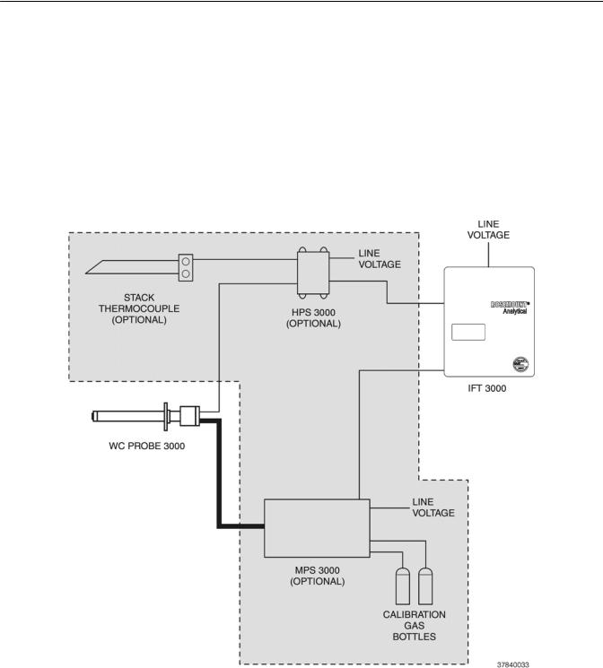
1.What is the line voltage being supplied to the IFT 3000? Write the line voltage here __________
2.Use the following drawing, Figure 1, to identify which parts of the World Class 3000 system are included in your system. Components in the shaded area are optional components.
Figure 1. Complete World Class 3000 System
Rosemount Analytical Inc. A Division of Emerson Process Management |
P-5 |

Instruction Manual
IB-106-300NH Rev. 4.3
May 2005
World Class 3000
QUICK START GUIDE
Use this Quick Start Guide if ...
1.You are using a World Class 3000 probe.
2.You are NOT using any optional components. Optional components are shown in the shaded area in Figure 1.
3.You are familiar with the installation requirements for the IFT 3000 Intelligent Field Transmitter and World Class 3000 probe.
4.You are familiar with the procedures for changing the jumpers located in the IFT 3000, as described in Section 2, Installation.
If you cannot use the Quick Start Guide, turn to Section 2, Installation, in this Instruction Manual.
P-6 |
Rosemount Analytical Inc. A Division of Emerson Process Management |

World Class 3000
Instruction Manual
IB-106-300NH Rev. 4.3
May 2005
QUICK START GUIDE FOR IFT 3000 SYSTEMS
Before using the Quick Start Guide, please read “WHAT YOU NEED TO KNOW BEFORE INSTALLING AND WIRING A ROSEMOUNT ANALYTICAL IFT 3000 INTELLIGENT FIELD TRANSMITTER WITH WORLD CLASS 3000 PROBE” on the preceding page.
1.Install the probe in an appropriate location on the stack or duct. Refer to Section 2, paragraph 2-1a for information on selecting a location for the probe.
2.Connect calibration gas and reference air to the probe.
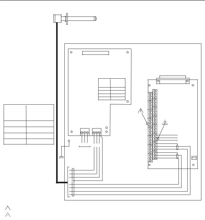
3.Verify the jumper selection on the IFT 3000 power supply board, microprocessor board, and interconnect board, as shown in Figure 2.
4.Install the IFT 3000 in the desired location. Refer to Section 2, paragraph 2-2a for information on selecting a location for the IFT 3000.
5.Wire the probe to the IFT as shown in Figure 2.
6.Connect line voltage to the IFT as shown in Figure 2.
7.Apply power to the IFT 3000. Allow sufficient time for the probe to reach normal operating temperature. The time required will vary based on process temperature and other variables.
8.Perform a manual (semiautomatic) calibration. Press the CAL key on the GUI. Select the PERFORM CALIBRATION sub-menu. “Press ENTER to start Manual Calibration” will appear on the LCD display. Press ENTER to start the calibration process. Follow the instructions on the LCD display. Refer to Section 4, Calibration, for more information on performing a calibration.
Rosemount Analytical Inc. A Division of Emerson Process Management |
P-7 |
Instruction Manual
IB-106-300NH Rev. 4.3
May 2005
World Class 3000
PROBE JUNCTION
BOX WIRING
|
|
CELL -VE |
CELL +VE |
CHROMEL |
|
ALUMEL |
|
|
|
}HEATER |
|||||||||||
|
|
GN |
OR |
YE |
|
RD |
|
GN |
BK |
|
BK |
||||||||||
|
|
|
|
|
|
|
|
|
|
|
|
|
|
|
|
|
|
|
|
|
|
|
|
|
|
|
|
|
|
|
|
|
|
|
|
|
|
|
|
|
|
|
|
|
|
1 |
|
2 |
|
3 |
|
4 |
5 |
6 |
7 |
|
8 |
|
|||||||
BL |
|
OR |
|
YE |
|
|
RD |
|
|
GN |
|
WH |
|
BK |
|
||||||
- |
|
+ |
|
+ |
|
|
- |
|
|
E |
|
R |
|
H |
|
||||||
MV |
|
MV |
|
TC |
|
|
TC |
|
|
|
|
|
|
|
|
|
|
||||
PROBE |
|
PROBE |
|
PROBE |
|
|
PROBE |
|
|
|
|
|
|
|
|
|
|
||||
|
|
|
|
|
|
|
|
|
|
|
|
|
|
|
|
|
|
|
|
|
|
|
|
|
|
|
|
|
|
|
|
|
|
|
|
|
|
|
|
|
|
|
|
LINE
VOLTAGE JUMPER SECTION (INSTALL)
100 V.A.C. JM3, JM7, JM2
120 V.A.C. JM8, JM7, JM1
220 V.A.C. JM6, JM5, JM2
240 V.A.C. JM6, JM5, JM1
LINE VOLTAGE
JUMPERS ON IFT
POWER SUPPLY
BOARD
WORLD CLASS
PROBE
INTELLIGENT FIELD TRANSMITTER IFT 3000
J1 3D39122G REV
POWER SUPPLY BOARD
LINE
VOLTAGE JUMPER
SECTION (INSTALL)
100 V.A.C. JM3, JM7, JM2
120 V.A.C. JM8, JM7, JM1
220 V.A.C. JM6, JM5, JM2
240 V.A.C. JM6, JM5, JM1
J5 J6
GND
STUD
L N E H R E
LINE
VOLTAGE
BK
WH
GN
PU
OR
BL
YE
RD
J2
J3
J4
J5
J6
J7
J8
RD YE
J9
BL
OR
J1
3D39120G REV
INTERCONNECT BOARD
SHIELD
STACK TC -
STACK TC +
SHIELD
PROBE TC -
PROBE TC +
SHIELD
PROBE MV -
PROBE M V +
JM1
NOTES:
 INSTALL JUMPER ACROSS TERMINALS 13 AND 14.
INSTALL JUMPER ACROSS TERMINALS 7 AND 8.
37840003
Figure 2. Wiring Layout for World Class 3000 System without HPS or MPS
P-8 |
Rosemount Analytical Inc. A Division of Emerson Process Management |

World Class 3000
Instruction Manual
IB-106-300NH Rev. 4.3
May 2005
QUICK REFERENCE GUIDE
IFT 3000 INTELLIGENT FIELD TRANSMITTER
Performing a Manual (Semiautomatic) Calibration
1.Connect the high calibration gas to the probe fitting.
2.Press the CAL key.
3.Select the PERFORM CALIBRATION sub-menu.
4.Press the ENTER key.
5.Turn on the high calibration gas.
6.When the O2 reading is stable, press ENTER.
7.Turn off the high calibration gas and turn on the low calibration gas.
8.Press Enter.
9.When the O2 reading is stable, press ENTER.
10.The LCD display will show “Resistance Check”. When the display changes to “Turn off low calibration gas”, turn off the low calibration gas and press ENTER.
11.When the oxygen reading has stabilized at the process value, press ENTER.
Setting up the Analog Output
1.Press the SETUP key.
2.Select the Analog Output sub-menu.
3.Set the SOURCE to O2. For information on configuring the analog output for Efficiency or Dual Range O2, refer to Section V, Operation.
4.Set the AOUT TYPE to the desired setting. Note that the setting must agree with the position of the analog output selector switch. If you will communicate with the IFT using HART communications, the AOUT TYPE must be set to HART 4-20mA.
5.Select Range Setup and press ENTER.
6.Set the Xfer Fnct to Lin or Log, as desired.
7.Select Range Values and press ENTER.
8.Set the High End to the oxygen concentration to be represented by the high analog output value, i.e., 20mA or 10V.
9.Set the Low End to the oxygen concentration to be represented by the low analog output value, i.e., 0 or 4mA or 0V.
10.Press the ESC key until you are back at the Main menu.
Rosemount Analytical Inc. A Division of Emerson Process Management |
P-9 |

Instruction Manual
IB-106-300NH Rev. 4.3
May 2005
World Class 3000
HART COMMUNICATOR FAST KEY SEQUENCES
|
Perform Calibration |
|
Analog Output Upper Range Value |
||||||||||
|
2 |
3 |
1 |
3 |
|
|
|
|
|
3 |
2 |
4 |
|
|
|
|
|
|
|
|
|
|
|
|
|
|
|
|
Trim Analog Output |
|
Analog Output Lower Range Value |
||||||||||
|
|
|
|
|
|
|
|
|
|
|
|
|
|
|
|
2 |
4 |
|
|
|
|
|
|
3 |
2 |
5 |
|
|
|
|
|
|
|
|
|
|
|
|
|
||
Toggle Analog Output Tracking |
|
|
|
View O2 Value |
|||||||||
|
2 |
3 |
1 |
2 |
|
|
|
|
|
1 |
1 |
1 |
|
|
|
|
|
|
|
|
|
|
|
|
|
|
|
|
|
|
|
View Analog Output |
|
|
|
||||||
|
|
|
|
|
|
|
|
|
|
|
|
|
|
|
|
|
|
|
1 |
2 |
1 |
|
|
|
|
|
|
|
|
|
|
|
|
|
|
|
|
|
|
|
|
Technical Support Hotline:
For assistance with technical problems, please call the Customer Support Center (CSC). The CSC is staffed 24 hours a day, 7 days a week.
Phone: 1-800-433-6076
In addition to the CSC, you may also contact Field Watch. Field Watch coordinates Rosemount Analytical’s field service throughout the US and abroad.
Phone: 1-800-654-RSMT (1-800-654-7768)
Rosemount Analytical may also be reached via the Internet through e-mail and the World Wide Web:
E-mail: GAS.CSC@emersonprocess.com
World Wide Web: www.raihome.com
P-10 |
Rosemount Analytical Inc. A Division of Emerson Process Management |

World Class 3000
Instruction Manual
IB-106-300NH Rev. 4.3
May 2005
SECTION 1
DESCRIPTION AND SPECIFICATIONS
1-1 COMPONENT CHECKLIST OF TYPICAL
SYSTEM (PACKAGE CONTENTS)
A typical Rosemount Analytical World Class 3000 Oxygen Analyzer with IFT 3000 Intelligent
Field Transmitter should contain the items shown in Figure 1-1. Record the part number, serial number, and order number for each component of your system in the table located on the first page of this manual.
|
1. |
Intelligent Field Transmitter |
|
2. |
Instruction Manual |
|
3. |
Multiprobe Calibration Gas Sequencer (Optional) |
|
4. |
Heater Power Supply (Optional) |
|
5. |
Oxygen Analyzer (Probe) |
|
6. |
System Cable |
1 |
7. |
Adapter Plate with mounting |
|
|
hardware and gasket |
28. Reference Air Set (If MPS not supplied)
9. HART® Communicator Package (Optional)
3
4
MAN 4275A00
English
October 1994
HART Communicator
o
TM
FISHER-ROSEMOUNT
8 |
5 |
9
6
7
37840019
Figure 1-1. Typical System Package
Rosemount Analytical Inc. A Division of Emerson Process Management |
Description and Specifications 1-1 |

Instruction Manual
IB-106-300NH Rev. 4.3
May 2005
World Class 3000
1-2 SYSTEM OVERVIEW
a.Scope
This Instruction Manual has been designed to supply details needed to install, startup, operate, and maintain the Rosemount Analytical World Class 3000 Oxygen Analyzer with IFT 3000 Intelligent Field Transmitter. The Intelligent Field Transmitter (IFT) can be interfaced with one World Class 3000 probe. The IFT provides all necessary intelligence for controlling the probe and optional MPS 3000 Multiprobe Calibration Gas Sequencer. Appendices at the back of this manual detail each component and option from the standpoint of troubleshooting, repair, and spare parts.
Operator/Technician interface to the IFT can be provided from the displays and key-
pads on the front panel, and remotely through HART® communications protocol, utilizing the 4-20 mA out-put signal from the IFT interconnect board. HART Communicator IFT applications are detailed in Appendix J.
b.System Description
The Rosemount Analytical Oxygen Analyzer (Probe) is designed to measure the net concentration of oxygen in an industrial process; i.e., the oxygen remaining after all fuels have been oxidized. The probe is permanently positioned within an exhaust duct or stack and performs its task without the use of a sampling system.
The equipment measures oxygen percentage by reading the voltage developed across a heated electrochemical cell, which consists of a small yttria-stabilized, zirconia disc. Both sides of the disc are coated with porous metal electrodes. When operated at the proper temperature, the millivolt output voltage of the cell is given by the following Nernst equation:
EMF = KT log10(P1/P2) + C
Where:
1.P2 is the partial pressure of the oxygen in the measured gas on one side of the cell,
2.P1 is the partial pressure of the oxygen in the reference air on the other side,
3.T is the absolute temperature,
4.C is the cell constant,
5.K is an arithmetic constant.
NOTE
For best results, use clean, dry, instrument air (20.95% oxygen) as a reference air.
When the cell is at operating temperature and there are unequal oxygen concentrations across the cell, oxygen ions will travel from the high partial pressure of oxygen side to the low partial pressure side of the cell. The resulting logarithmic output voltage is approximately 50 mV per decade. Because the magnitude of the output is proportional to the logarithm of the inverse of the sample of the oxygen partial pressure, the output signal increases as the oxygen concentration of the sample gas decreases. This characteristic enables the oxygen analyzer to provide exceptional sensitivity at low oxygen concentrations.
Oxygen analyzer equipment measures net oxygen concentration in the presence of all the products of combustion, including water vapor. Therefore, it may be considered an analysis on a "wet" basis. In comparison with older methods, such as the Orsat apparatus, which provides an analysis on a "dry" gas basis, the "wet" analysis will, in general, indicate a lower percentage of oxygen. The difference will be proportional to the water content of the sampled gas stream.
1-2 Description and Specifications |
Rosemount Analytical Inc. A Division of Emerson Process Management |
 Loading...