


Form Number A6175
Part Number D301217X012
March 2006
ROC827 Remote Operations Controller
Instruction Manual
Flow Computer Division
Revision Tracking Sheet
March 2006
This manual may be revised periodically to incorporate new or updated information. The revision date of each page appears at the bottom of the page opposite the page number. A change in revision date to any page also changes the date of the manual that appears on the front cover. Listed below is the revision date of each page (if applicable):
Page |
Revision |
Initial issue |
Mar-06 |
ROCLINK is a trademark of one of the Emerson Process Management companies. The Emerson logo is a trademark and service mark of Emerson Electric Co. All other marks are the property of their respective owners.
© Fisher Controls International, LLC. 2006. All rights reserved. Printed in the U.S.A. www.EmersonProcess.com/flow
While this information is presented in good faith and believed to be accurate, Fisher Controls does not guarantee satisfactory results from reliance upon such information. Nothing contained herein is to be construed as a warranty or guarantee, express or implied, regarding the performance, merchantability, fitness or any other matter with respect to the products, nor as a recommendation to use any product or process in conflict with any patent. Fisher Controls reserves the right, without notice, to alter or improve the designs or specifications of the products described herein.
Issued Mar-06 |
ii |
Contents
Chapter 1 – General Information |
1-1 |
||
1.1 |
Scope of Manual............................................................................................................... |
1-1 |
|
1.2 |
Hardware .......................................................................................................................... |
1-2 |
|
|
1.2.1 Central Processor Unit (CPU) ............................................................................ |
1-5 |
|
|
1.2.2 |
Processor and Memory ...................................................................................... |
1-6 |
|
1.2.3 |
Real-Time Clock (RTC) ...................................................................................... |
1-6 |
|
1.2.4 |
Diagnostic Monitoring......................................................................................... |
1-7 |
|
1.2.5 |
Options ............................................................................................................... |
1-7 |
1.3 |
FCC Information ............................................................................................................... |
1-8 |
|
1.4 |
Firmware........................................................................................................................... |
1-8 |
|
|
1.4.1 Historical Database and Event & Alarm Log.................................................... |
1-11 |
|
|
1.4.2 Meter Runs and Stations.................................................................................. |
1-12 |
|
|
1.4.3 |
Flow Calculations ............................................................................................. |
1-12 |
|
1.4.4 |
Automatic Self Tests ........................................................................................ |
1-13 |
|
1.4.5 |
Low Power Modes............................................................................................ |
1-13 |
|
1.4.6 Proportional, Integral, and Derivative (PID) ..................................................... |
1-14 |
|
|
1.4.7 Function Sequence Table (FST) ...................................................................... |
1-14 |
|
1.5 |
ROCLINK 800 Configuration Software........................................................................... |
1-15 |
|
1.6 |
DS800 Development Suite Software.............................................................................. |
1-16 |
|
1.7 |
Expanded Backplane...................................................................................................... |
1-17 |
|
1.8 |
Related Specification Sheets.......................................................................................... |
1-18 |
|
Chapter 2 – Installation and Use |
2-1 |
||
2.1 |
Installation Requirements ................................................................................................. |
2-1 |
|
|
2.1.1 |
Environmental Requirements ............................................................................. |
2-2 |
|
2.1.2 |
Site Requirements .............................................................................................. |
2-2 |
|
2.1.3 |
Compliance with Hazardous Area Standards .................................................... |
2-3 |
|
2.1.4 |
Power Installation Requirements ....................................................................... |
2-4 |
|
2.1.5 |
Grounding Installation Requirements ................................................................. |
2-4 |
|
2.1.6 |
I/O Wiring Requirements .................................................................................... |
2-5 |
2.2 |
Required Tools ................................................................................................................. |
2-5 |
|
2.3 |
Housing |
............................................................................................................................. |
2-5 |
|
2.3.1 |
Removing and Replacing End Caps .................................................................. |
2-6 |
|
2.3.2 |
Removing and Installing Wire Channel Covers .................................................. |
2-6 |
|
2.3.3 ............................................................ |
Removing and Installing Module Covers |
2-7 |
2.4 |
Mounting ...............................................................................the ROC827 on a DIN Rail |
2-7 |
|
|
2.4.1 ......................................................................................... |
Installing the DIN Rail |
2-9 |
|
2.4.2 ............................................................... |
Securing the ROC827 on the DIN Rail |
2-9 |
|
2.4.3 ....................................................... |
Removing the ROC827 from the DIN Rail |
2-10 |
2.5 |
ROC800 ................................................................-Series Expanded Backplane (EXP) |
2-10 |
|
|
2.5.1 ............................................................... |
Attaching an Expandable Backplane |
2-11 |
|
2.5.2 .............................................................. |
Removing an Expandable Backplane |
2-12 |
2.6 |
Central Processor ........................................................................................Unit (CPU) |
2-13 |
|
|
2.6.1 .............................................................................. |
Removing the CPU Module |
2-16 |
|
2.6.2 ................................................................................ |
Installing the CPU Module |
2-16 |
2.7 |
License ..................................................................................................................Keys |
2-17 |
|
|
2.7.1 .................................................................................... |
Installing a License Key |
2-18 |
|
2.7.2 .................................................................................. |
Removing a License Key |
2-19 |
Issued Mar-06 |
|
iii |
|
2.8 Startup and Operation .................................................................................................... |
2-19 |
|
2.8.1 |
Startup.............................................................................................................. |
2-20 |
2.8.2 |
Operation.......................................................................................................... |
2-20 |
Chapter 3 – Power Connections |
3-1 |
|
3.1 |
Power Input Module Descriptions..................................................................................... |
3-1 |
|
3.1.1 12-Volt DC Power Input Module (PM-12)........................................................... |
3-1 |
|
3.1.2 24-Volt DC Power Input Module (PM-24)........................................................... |
3-3 |
|
3.1.3 Auxiliary Output (AUX+ and AUX–).................................................................... |
3-4 |
|
3.1.4 Switched Auxiliary Output (AUXSW+ and AUXSW–) ........................................ |
3-6 |
3.2 |
Determining Power Consumption..................................................................................... |
3-7 |
|
3.2.1 Tuning the Configuration.................................................................................. |
3-11 |
3.3 |
Removing a Power Input Module ................................................................................... |
3-20 |
3.4 |
Installing a Power Input Module ..................................................................................... |
3-21 |
3.5 |
Connecting the ROC827 to Wiring ................................................................................. |
3-21 |
|
3.5.1 Wiring the DC Power Input Module.................................................................. |
3-22 |
|
3.5.2 Wiring the External Batteries............................................................................ |
3-23 |
|
3.5.3 Replacing the Internal Battery.......................................................................... |
3-25 |
3.6 |
Related Specification Sheets.......................................................................................... |
3-26 |
Chapter 4 – Input/Output Modules |
4-1 |
||
4.1 |
I/O Module Overview ........................................................................................................ |
4-1 |
|
4.2 |
Installation......................................................................................................................... |
4-3 |
|
|
4.2.1 |
Installing an I/O Module...................................................................................... |
4-4 |
|
4.2.2 |
Removing an I/O Module.................................................................................... |
4-5 |
|
4.2.3 |
Wiring I/O Modules............................................................................................. |
4-6 |
4.3 |
Analog Input Modules....................................................................................................... |
4-6 |
|
4.4 |
Analog Output Modules .................................................................................................... |
4-8 |
|
4.5 |
Discrete Input Modules..................................................................................................... |
4-9 |
|
4.6 |
Discrete Output Modules ................................................................................................ |
4-10 |
|
4.7 |
Discrete Output Relay Modules...................................................................................... |
4-11 |
|
4.8 |
Pulse Input Modules ....................................................................................................... |
4-12 |
|
4.9 |
RTD Input Modules......................................................................................................... |
4-14 |
|
|
4.9.1 |
Connecting the RTD Wiring.............................................................................. |
4-15 |
4.10 J and K Type Thermocouple Input Modules.................................................................. |
4-16 |
||
4.11 |
Related Specification Sheets......................................................................................... |
4-21 |
|
Chapter 5 – Communications |
5-1 |
|
5.1 |
Communications Ports and Modules Overview............................................................... |
5-1 |
5.2 |
Installing Communication Modules .................................................................................. |
5-3 |
5.3 |
Removing a Communications Module ............................................................................. |
5-4 |
5.4 |
Wiring Communications Modules .................................................................................... |
5-5 |
5.5 |
Local Operator Interface (LOI)......................................................................................... |
5-5 |
|
5.5.1 Using the LOI ..................................................................................................... |
5-7 |
5.6 |
Ethernet Communications................................................................................................ |
5-7 |
5.7 |
EIA-232 (RS-232) Serial Communications ...................................................................... |
5-9 |
5.8 |
EIA-422/485 (RS-422/485) Serial Communications Module ......................................... |
5-10 |
|
5.8.1 EIA-422/485 (RS-422/485) Jumpers & Termination Resistors ........................ |
5-11 |
Issued Mar-06 |
iv |
5.9 |
Dial-up Modem Communications Module...................................................................... |
5-12 |
5.10 |
Multi-Variable Sensor (MVS) Interface Modules............................................................ |
5-14 |
5.11 |
HART Interface Module ................................................................................................. |
5-16 |
5.12 |
Related Specification Sheets......................................................................................... |
5-20 |
Chapter 6 – Troubleshooting |
6-1 |
||
6.1 |
Guidelines......................................................................................................................... |
6-1 |
|
6.2 |
Checklists ......................................................................................................................... |
6-2 |
|
|
6.2.1 |
Serial Communications ...................................................................................... |
6-2 |
|
6.2.2 |
I/O Point.............................................................................................................. |
6-2 |
|
6.2.3 |
Software ............................................................................................................. |
6-3 |
|
6.2.4 |
Powering Up....................................................................................................... |
6-3 |
|
6.2.5 |
MVS Module....................................................................................................... |
6-3 |
6.3 |
Procedures ....................................................................................................................... |
6-4 |
|
|
6.3.1 |
Preserving Configuration and Log Data ............................................................. |
6-4 |
|
6.3.2 |
Restarting the ROC827 ...................................................................................... |
6-4 |
|
6.3.3 |
Troubleshooting Analog Input Modules.............................................................. |
6-5 |
|
6.3.4 |
Troubleshooting Analog Output Modules........................................................... |
6-7 |
|
6.3.5 |
Troubleshooting Discrete Input Modules............................................................ |
6-7 |
|
6.3.6 |
Troubleshooting Discrete Output Modules......................................................... |
6-8 |
|
6.3.7 |
Troubleshooting Discrete Output Relay Modules............................................... |
6-8 |
|
6.3.8 |
Troubleshooting Pulse Input Modules................................................................ |
6-8 |
|
6.3.9 |
Troubleshooting RTD Input Modules ................................................................. |
6-9 |
|
6.3.10 |
Troubleshooting J and K Type Thermocouple Input Modules ......................... |
6-10 |
Chapter 7 – Calibration |
7-1 |
|
7.1 |
Calibration......................................................................................................................... |
7-1 |
7.2 |
Preparing for Calibration................................................................................................... |
7-1 |
Appendix A – Glossary |
A-1 |
|
|
|
|
Index |
|
I-1 |
Issued Mar-06 |
v |
Issued Mar-06 |
vi |

ROC827 Instruction Manual
Chapter 1 – General Information
This manual focuses on the hardware aspects of the ROC827 Remote Operations Controller (the “ROC827”) and the ROC800-Series expanded backplanes (“EXPs”). For information about the software, refer to the
ROCLINK™ 800 Configuration Software User Manual (Form A6121).
This chapter details the structure of this manual and provides an overview of the ROC827 and its components.
In This Chapter
1.1 |
Scope of Manual...................................................................................... |
1-1 |
1.2 |
Hardware ................................................................................................. |
1-2 |
|
1.2.1 Central Processor Unit (CPU)........................................................ |
1-5 |
|
1.2.2 Processor and Memory.................................................................. |
1-6 |
|
1.2.3 Real-Time Clock (RTC).................................................................. |
1-6 |
|
1.2.4 Diagnostic Monitoring .................................................................... |
1-7 |
|
1.2.5 Options........................................................................................... |
1-7 |
1.3 |
FCC Information ...................................................................................... |
1-8 |
1.4 |
Firmware.................................................................................................. |
1-8 |
|
1.4.1 Historical Database and Event & Alarm Log................................ |
1-12 |
|
1.4.2 Meter Runs and Stations ............................................................. |
1-12 |
|
1.4.3 Flow Calculations......................................................................... |
1-12 |
|
1.4.4 Automatic Self Tests .................................................................... |
1-13 |
|
1.4.5 Low Power Modes ....................................................................... |
1-14 |
|
1.4.6 Proportional, Integral, and Derivative (PID)................................. |
1-14 |
|
1.4.7 Function Sequence Table (FST).................................................. |
1-15 |
1.5 |
ROCLINK 800 Configuration Software.................................................. |
1-15 |
1.6 |
DS800 Development Suite Software ..................................................... |
1-17 |
1.7 |
Expanded Backplane............................................................................. |
1-18 |
1.8 |
Related Specification Sheets................................................................. |
1-19 |
The ROC827 Remote Operations Controller is a microprocessor-based controller that provides the functions required for a variety of field automation applications. The ROC827 is ideal for applications requiring general logic and sequencing control; historical data archiving; multiple communication ports; Proportional, Integral, and Derivative (PID) control; and flow measurement on up to twelve meter runs. When attached to the ROC827, the ROC800-Series expanded backplanes provide the ROC827 with increased I/O capabilities.
1.1Scope of Manual
This manual contains the following chapters:
Chapter 1 |
Provides an overview of the hardware and |
General Information |
specifications for the ROC827 and the ROC800-Series |
|
expanded backplane. |
Issued Mar-06 |
General Information |
1-1 |

ROC827 Instruction Manual
Chapter 2
Installation and Use
Chapter 3
Power Connections
Chapter 4
Input/Output (I/O)
Modules
Chapter 5
Communications
Chapter 6
Troubleshooting
Chapter 7
Calibration
Provides information on installation, tools, wiring, mounting the ROC827, and other essential elements of the ROC827 and EXPs.
Provides information on the Power Input modules available for the ROC827 and EXPs and provides worksheets to help determine power requirements for the ROC827 configurations.
Provides information for the Input/Output (I/O) modules available for the ROC827 and EXPs.
Provides information for the built-in communications and the optional communication modules available for the ROC827.
Provides information on diagnosing and correcting problems for the ROC827.
Provides information for calibrating Analog Inputs, HART Inputs, RTD Inputs, and MVS Inputs for the ROC827.
Glossary |
Provides definitions of acronyms and terms. |
Index |
Provides an alphabetic listing of items and topics |
|
contained in this manual. |
1.2Hardware
The ROC827 is highly innovative and versatile with an integrated backplane to which the central processor unit (CPU), Power Input module, communication modules, and I/O modules connect. The ROC827 has three I/O module slots.
The ROC800-Series expanded backplane (EXP) attaches to the ROC827. Each EXP provides six additional I/O module slots. The ROC827 can support up to four EXPs, for a total of 27 I/O module slots in a fully configured ROC827 (six slots per EXP plus the three I/O slots on the ROC827 itself).
The ROC827 uses a Power Input module to convert external input power to the voltage levels required by the ROC827’s electronics and to monitor voltage levels to ensure proper operation. Two Power Input modules—12 Volts dc (PM-12) and 24 Volts dc (PM-24)—are available for the ROC827. For more information on the Power Input modules, refer to Chapter 3, Power Connections.
The ROC827 supports a variety of communication protocols: ROC Plus, Modbus, Modbus TCP/IP, Modbus encapsulated in TCP/IP, and Modbus with Electronic Flow Measurement (EFM) extensions.
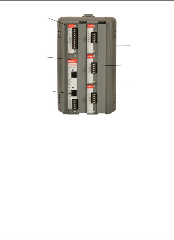
Figure 1-1 shows the housing, typical I/O modules, and communication modules installed in a ROC827. The patented ABS (Acrylonitrile Butadiene Styrene) plastic housing has wire covers to protect the wiring terminals. The housing includes DIN rail mounts for mounting the ROC827 on a panel or in a user-supplied enclosure.
Issued Mar-06 |
General Information |
1-2 |
ROC827 Instruction Manual
Power Supply Module
I/O Module (1 of 3)
CPU
Wire Channel Cover
LOI (Local Port)
EIA-232 (RS-232D) 
Right End Cap
Built-in Ethernet (Comm1)
Built-in EIA-232 (RS-232C)
(Comm2)
Figure 1-1. ROC827 Base Unit (without Expanded Backplane)
The ROC827’s CPU contains the microprocessor, the firmware, a connector to the backplane, three built-in communication ports, a LightEmitting Diode (LED) low power wakeup button, a RESET button, the application license key connectors, a STATUS LED indicating system integrity, diagnostic LEDs for two of the communications ports, and the main processor.
Issued Mar-06 |
General Information |
1-3 |

ROC827 Instruction Manual
Figure 1-2 shows a typical expanded backplane (EXP) populated with a full complement of six I/O modules. Each EXP is composed of the same plastic housing as the ROC827, contains six I/O slots, and has a powered backplane that easily attaches to the ROC827 and other EXPs.
Figure 1-2. ROC827 with One Expanded Backplane
The ROC827 and EXPs support nine types of Input/Output (I/O) modules, which can satisfy a wide variety of field I/O requirements (refer to Chapter 4, Input/Output Modules). I/O modules include:
Analog Inputs (AI).
Analog Outputs (AO).
Discrete Inputs (DI).
Discrete Outputs (DO).
Digital Relay Outputs (DOR).
HART Inputs/Outputs.
Pulse Inputs (PI) – High/Low Speed.
Resistance Temperature Detector Inputs (RTD).
J and K Type Thermocouple (T/C) Inputs.
Issued Mar-06 |
General Information |
1-4 |
ROC827 Instruction Manual
The ROC827 holds up to six communication ports (refer to Chapter 5,
Communications). Three communication ports are built-in:
Local Operator Interface (LOI) – Local Port EIA-232 (RS-232D).
Ethernet – Comm1 Port for use with the DS800 Development Suite Software.
EIA-232 (RS-232C) – Comm2 Port for point-to-point asynchronous serial communications.
Communication modules (which install in the ROC827’s Comm3, Comm4, and Comm5 slots) provide additional ports for communicating with a host computer or other devices. Modules include:
EIA-232 (RS-232C) – Point-to-point asynchronous serial communications include Data Terminal Ready (DTR) support, Ready To Send (RTS) support, and radio power control.
EIA-422/EIA-485 (RS-422/RS-485) – Point-to-point (EIA-422) or multiple-point (EIA-485) asynchronous serial communications.
Multi-Variable Sensor (MVS) – Interfaces with MVS Sensors (up to two modules per ROC827).
Dial-up modem – Communications over a telephone network (14.4K V.42 bis with throughput up to 57.6K bps).
Hot-Swappable & Modules—whether I/O or communication—easily install in the Hot-Pluggable module slots. Modules are both “hot-swappable” (they can be
removed and another module of the same kind installed while the ROC827 is powered) and “hot-pluggable” (they can be installed directly into unused module slots with the ROC827 is powered).
Modules are also self-identifying, which means that the ROCLINK 800 Configuration software recognizes the module (although you may need to configure the module using the software). The modules have extensive short circuit, overvoltage protection, and are self-resetting after a fault clears.
1.2.1 Central Processor Unit (CPU)
The CPU contains the microprocessor, the firmware, connectors to the backplane, the three built-in communication ports (two with LEDs), a LED low power wakeup button, a RESET button, the application license key connectors, a STATUS LED indicating system integrity, and the main processor.
CPU components include:
32-bit microprocessor based on Motorola® MPC862 Quad Integrated Communications Controller (PowerQUICC™) PowerPC® processor.
SRAM (Static Random Access Memory) with battery backup.
Flash ROM (Read-Only Memory).
SDRAM (Synchronous Dynamic Random Access Memory).
Issued Mar-06 |
General Information |
1-5 |

ROC827 Instruction Manual
Diagnostic monitoring.
Real-Time Clock.
Automatic self-tests.
Power saving modes.
Local Operator Interface (LOI) EIA-232 (RS-232D) Local Port.
EIA-232 (RS-232C) serial Comm2 port.
Ethernet Comm1 port.
1.2.2Processor and Memory
The ROC827 uses a 32-bit microprocessor with processor bus clock frequency at 50 MHz with a watchdog timer. The Motorola MPC862 Quad Integrated Communications Controller (PowerQUICC) PowerPC processor and the Real-Time Operating System (RTOS) provide both hardware and software memory protection.
1.2.3 Real-Time Clock (RTC)
You can set the ROC827’s Real-Time Clock (RTC) for year, month, day, hour, minute, and second. The clock provides time stamping of the database values. The battery-backed clock firmware tracks the day of the week, corrects for leap year, and adjusts for daylight savings time (userselectable). The time chip automatically switches to backup power when the ROC827 loses primary input power.
The internal Sanyo 3-volt CR2430 lithium battery provides backup for the data and the Real-Time Clock when the main power is not connected. The battery has a one-year minimum backup life with the battery is installed, the jumper disengaged, and no power applied to the ROC827. The battery has a ten-year backup life with the backup battery installed and power applied to the ROC827 or when the battery is removed from the ROC827.
Note: If the Real-Time Clock does not keep the current time when you remove power, replace the lithium battery.
Issued Mar-06 |
General Information |
1-6 |

ROC827 Instruction Manual
1.2.4 Diagnostic Monitoring
The ROC827 has diagnostic inputs incorporated into the circuitry for monitoring system integrity. Use ROCLINK 800 software to access the System Analog Inputs. Refer to Table 1-1.
Table 1-1. System Analog Inputs
System AI |
Function |
Normal Range |
|
Point Number |
|||
|
|
||
1 |
Battery Input Voltage |
11.25 to 16 Volts dc |
|
2 |
Charge in Voltage |
0 to 18 Volts dc |
|
3 |
Module Voltage |
11.00 to 14.50 Volts dc |
|
4 |
Not Used |
Not Used |
|
5 |
On Board Temperature |
–40 to 85°C (–40 to |
|
|
|
185°F) |
1.2.5 Options
The ROC827 allows you to choose from a wide variety of options to suit many applications.
Optional communication modules include EIA-232 (RS-232) serial communications, EIA-422/485 (RS-422/485) serial communications, Multi-Variable Sensor (MVS), and dial-up modem communications (refer to Chapter 5, Communications).
The ROC827 can handle up to two MVS interface modules. Each module can provide power and communications for up to six MVS sensors, for a total of up to 12 MVS sensors per ROC827 (refer to Chapter 5,
Communications).
Optional I/O modules include Analog Inputs (AI), Analog Outputs (AO), Discrete Inputs (DI), Discrete Outputs (DO), Discrete Output Relays (DOR), Pulse Inputs (PI), Resistance Temperature Detector (RTD) Inputs, Thermocouple (T/C) Inputs, and Highway Addressable Remote Transducers (HART) (refer to Chapter 4, Input/Output Modules).
The optional application license keys provide extended functionality, such as the use of the DS800 Development Suite Software (the IEC 61131-3 compliant programming environment) and various user programs, and enables embedded meter runs. For example, you need to install a license key with the proper license in the ROC827 to perform AGA calculations. Refer to Section 1.6, “DS800 Development Suite Software.”
The Local Operator Interface (LOI local port) communications terminal requires the installation of an LOI cable between the ROC827 and your PC. The LOI port uses an RJ-45 connector with a standard EIA-232 (RS-232D) pin out.
Issued Mar-06 |
General Information |
1-7 |

ROC827 Instruction Manual
1.3FCC Information
This equipment complies with Part 68 of the FCC rules. Etched on the modem assembly is, among other information, the FCC certification number and Ringer Equivalence Number (REN) for this equipment. If requested, this information must be provided to the telephone company.
This module has an FCC-compliant telephone modular plug. The module is designed to be connected to the telephone network or premises’ wiring using a compatible modular jack that is Part 68-compliant.
The REN is used to determine the quantity of devices that may be connected to the telephone line. Excessive RENs on the telephone line may result in the devices not ringing in response to an incoming call. Typically, the sum of the RENs should not exceed five (5.0). Contact the local telephone company to determine the total number of devices that may be connected to a line (as determined by the total RENs).
If this equipment and its dial-up modem causes harm to the telephone network, the telephone company will notify you in advance that temporary discontinuance of service may be required. However, if advance notice is not practical, the telephone company will notify the customer as soon as possible. In addition, you will be advised of your right to file a complaint with the FCC if you believe it necessary.
The telephone company may make changes to its facilities, equipment, operations, or procedures that could affect the operation of the equipment. If this happens, the telephone company will provide advance notice so you can make the necessary modifications to maintain uninterrupted service.
If you experience trouble with this equipment or the dial-up modem, contact Emerson Process Management’s Flow Computer Division (at 641- 754-3923) for repair or warranty information. If the equipment harms the telephone network, the telephone company may request that you disconnect the equipment until the problem is resolved.
1.4Firmware
The firmware that resides in Flash Read-Only Memory (ROM) contains the operating system, ROC Plus communications protocol, and application software. The CPU module provides battery-backed Static Random Access Memory (SRAM) for saving configurations, storing events, alarms, and the historical logs.
The ROC800-Series Operating System firmware provides a complete operating system for the ROC827. The firmware in the ROC827 is fieldupgradeable using a serial connection or the Local Operator Interface (LOI) local port. For more information, refer to the ROCLINK 800 Configuration Software User Manual (Form A6121).
The firmware supports:
Input/Output Database.
Issued Mar-06 |
General Information |
1-8 |

ROC827 Instruction Manual
Historical Database.
Event and Alarm Log Databases.
Applications (PID, AGA, FST, and such).
Measurement Station Support.
Determining Task Execution.
Real-Time Clock.
Establishing and Managing Communications.
Self-Test Capability.
The firmware makes extensive use of configuration parameters, which you configure using ROCLINK 800 software.
RTOS The ROC800-Series firmware uses a pre-emptive, multi-tasking, message-based Real-Time Operating System (RTOS) with hardwaresupported memory protection. Tasks are assigned priorities and, at any given time, the operating system determines which task will run. For instance, if a lower priority task is executing and a higher priority task needs to run, the operating system suspends the lower priority task, allows the higher priority task to run to completion, then resumes the lower priority task’s execution. This is more efficient than a “time sliced” architecture type.
TLP The ROC827 reads data from and writes data to data structures called “points.” A “point” is a ROC Plus Protocol term for a grouping of individual parameters (such as information about an I/O channel) or some other function (such as a flow calculation). Points are defined by a collection of parameters and have a numerical designation that defines the type of point (for example, point type 101 refers to a Discrete Input and point type 103 refers to an Analog Input).
The logical number indicates the physical location for the I/O or the logical instance for non-I/O points within the ROC827. Parameters are individual pieces of data that relate to the point type. For instance, the raw A/D value and the low scaling value are parameters associated with the Analog Input point type, 103. The point type attributes define the database point to be one of the possible types of points available to the system.
Together, these three components—the type (T), the logical (L), and the parameters (P)—can be used to identify specific pieces of data that reside in a ROC827’s data base. Collectively, this three-component address is often called a “TLP.”
I/O Database The Input/Output database contains the input and output points the operating system firmware supports, including the System Analog Inputs, Multi-Variable Sensor (MVS) inputs, and Input/Output (I/O) modules. The firmware automatically determines the point type and point number location of each installed I/O module. It then assigns each input and output to a point in the database and includes userdefined configuration parameters for assigning values, statuses, or identifiers. The firmware scans each input, placing the values into the
Issued Mar-06 |
General Information |
1-9 |

ROC827 Instruction Manual
respective database point. These values are available for display and historical archiving.
SRBX Spontaneous-Report-by-Exception (SRBX or RBX) communication allows the ROC827 to monitor for alarm conditions and, upon detecting an alarm, automatically reports the alarm to a host computer. Any kind of communications link—dial-up modem or serial line—can perform SRBX as long as the host is set up to receive field-initiated calls.
Protocols The firmware supports both the ROC Plus protocol and the Modbus master and slave protocol. ROC Plus protocol can support serial communications and radio or telephone modem communications to local or remote devices, such as a host computer. The firmware also supports the ROC Plus protocol over TCP/IP on the Ethernet port. The ROC Plus protocol is similar to the ROC 300/400/500 protocol, since it used many of the same opcodes. For more information, contact your local sales representative.
The ROC800-Series firmware also supports Modbus protocol as either master or slave device using Remote Terminal Unit (RTU) or American Standard Code for Information Interchange (ASCII) modes. This allows you to easily integrate the ROC827 into other systems. Extensions to the Modbus protocol allow the retrieval of history, event, and alarm data in Electronic Flow Metering (EFM) Measurement applications.
Note: In Ethernet mode, the firmware support Modbus only in slave mode.
Security The ROCLINK 800 software also secures access to the ROC827. You can define and store a maximum of 16 case-sensitive user identifiers (User IDs). In order for the ROC827 to communicate, a case sensitive log-on ID supplied to the ROCLINK 800 software must match one of the IDs stored in the ROC827.
The operating system firmware supports the application-specific firmware supplied in the Flash ROM. The application firmware includes Proportional, Integral, and Derivative (PID) Control; FSTs; Spontaneous- Report-By-Exception (SRBX) Communications Enhancement; optional American Gas Association (AGA) Flow calculations with station support; and optional IEC 61131-3 language programs (using DS800 Development Suite software). Applications reside, so you do not need to re-build and download the firmware for changes in calculation method.
Input Module The ROC800-Series firmware, by default, supports 16 addressable Addressing points per module slot. However, to accommodate all the ROC827’s
expanded input capabilities (up to 27 module slots), you must set the firmware to support eight (8) addressable points per module slot. (Accomplish this using ROCLINK 800 and selecting ROC > Information. On the Device Information screen’s General tab, click the 8-Points Per Module radio button in the Logical Compatibility Mode frame.)
Issued Mar-06 |
General Information |
1-10 |

ROC827 Instruction Manual
The difference between 16-point and 8-point addressing becomes critical when you have a host device reading data from specific TLPs. For example, under 16-point addressing, channel 2 for a DI module in slot 2 is referenced by TLP 101,33,3. Under 8-point addressing, channel 2 for a DI module in slot 2 is referenced by TLP 101,17,23. Table 1-2 illustrates the difference between 8-point and 16-point addressing.
Table 1-2. 16-Point vs. 8-Point Addressing
Slot Number |
Logicals (16 pt) |
Logicals (8 pt) |
0 |
0–15 |
0–7 |
1 |
16–31 |
8–15 |
2 |
32–47 |
16–23 |
3 |
48–63 |
24–31 |
4 |
64–79 |
32–39 |
5 |
80–95 |
40–47 |
6 |
96–111 |
48–55 |
7 |
112–127 |
56–63 |
8 |
128–143 |
64–71 |
9 |
144–159 |
72–79 |
10 |
N/A |
80–87 |
11 |
N/A |
88–95 |
12 |
N/A |
96–103 |
13 |
N/A |
104–111 |
14 |
N/A |
112–119 |
15 |
N/A |
120–127 |
16 |
N/A |
128–135 |
17 |
N/A |
136–143 |
18 |
N/A |
144–151 |
19 |
N/A |
152–159 |
20 |
N/A |
160–167 |
21 |
N/A |
168–175 |
22 |
N/A |
176–183 |
23 |
N/A |
184–191 |
24 |
N/A |
192–199 |
25 |
N/A |
200–207 |
26 |
N/A |
208–215 |
27 |
N/A |
216–223 |
Note: 16-point addressing is the default for the ROC800-Series firmware. To maximize the expanded input capabilities of the ROC827, you must use ROCKLINK 800 to modify the firmware addressing to use 8-points per module.
1.4.1 Historical Database and Event & Alarm Log
The historical database provides archiving of measured and calculated values for either on-demand viewing or saving to a file. It provides an historical record in accordance with API Chapter 21.1. You can configure each of up to 200 points in the historical database to archive values under various schemes, such as averaging or accumulating, as appropriate for the type of database point.
Issued Mar-06 |
General Information |
1-11 |

ROC827 Instruction Manual
The historical database is maintained in 11 segments. You can configure each segment in the database to archive selected points at specified time intervals. The segments can continuously archive or can be turned on and off.
You can distribute history points among history segments 1 through 10 and the general history segment. For each history segment, you can configure the number of periodic history values archived, the frequency of archiving periodic values, the number of daily values archived, and the contract hour. The number of minute values is fixed at 60. The 200 points provide a total of over 197,000 entries (equal to more than 35 days of 24hour data for 200 points).
The Event Log records the last 450 parameter changes, power on and off cycles, calibration information, and other system events. The event is recorded along with a date and time stamp. The Alarm Log records the last 450 configured occurrences of alarms (set and clear). You can view the logs, save them to a disk file, or print them using ROCLINK 800 software.
1.4.2 Meter Runs and Stations
You can group similarly configured meter runs into stations, which provide great benefits during configuration and reporting. You can also configure each meter run, which eliminates redundant meter run data within a station and enables faster data processing.
You can group meter runs among the maximum of twelve stations in any combination. Meter runs belong in the same station when they have the same gas composition data and calculation methods. Stations allow you to:
Set contract hours differently for each station.
Designate several individual meter runs as part of a station.
Configure one to twelve meter runs for each station.
1.4.3Flow Calculations
Gas and liquid calculation methods include:
AGA and API Chapter 21 compliant for AGA linear and differential meter types.
AGA 3 – Orifice Plates for gas.
AGA 7 – Turbine Meters (ISO 9951) for gas.
AGA 8 – Compressibility for Detailed (ISO 12213-2), Gross I (ISO 12213-3), and Gross II for gas.
ISO 5167 – Orifice Plates for liquid.
API 12 – Turbine Meters for liquid.
ROC827 firmware completes full calculations every second on all configured runs (up to 12) for AGA 3, AGA 7, AGA 8, ISO 5167, and ISO 9951.
Issued Mar-06 |
General Information |
1-12 |

ROC827 Instruction Manual
AGA 3 calculations conform to the methods described in American Gas Association Report No. 3, Orifice Metering of Natural Gas and Other Related Hydrocarbon Fluids. Based on the second and third editions, the calculation method is 1992 AGA 3.
The AGA 7 calculations conform to methods described in American Gas Association Report No. 7, Measurement of Gas by Turbine Meters, and use the AGA 8 method for determining the compressibility factor.
The AGA 8 method calculates the compressibility factor based on the physical chemistry of the component gasses at specified temperatures and pressures.
The firmware supports liquid calculation methods ISO 5167 and API 12. Factors for API 12 correction must be supplied through a Function Sequence Table (FST) or user program. For more information, refer either to the Function Sequence Table (FST) User Manual (Form A4625) or the ROCLINK 800 Configuration Software User Manual (Form A6121).
1.4.4 Automatic Self Tests
The operating system firmware supports diagnostic tests on the ROC827 hardware, such as RAM integrity, Real-Time Clock operation, input power voltage, board temperature, and watchdog timer.
The ROC827 periodically performs the following self-tests:
Voltage tests (battery low and battery high) ensure the ROC827 has enough power to run while not allowing the battery to be overcharged. The ROC827 operates with 12 Volts dc (nominal) power. The LEDs become active when input power with the proper polarity and startup voltage (9.00 to 11.25 Volts dc) is applied to the BAT+ / BAT– connectors. Refer to Table 1-1.
The CPU controls the software “watchdog.” This watchdog checks the software for validity every 2.7 seconds. If necessary, the processor automatically resets.
The ROC827 monitors Multi-Variable Sensor(s), if applicable, for accurate and continuous operation.
A memory validity self-test is performed to ensure the integrity of memory.
1.4.5Low Power Modes
The ROC827 uses low power operation under predetermined conditions and supports two low power modes, Standby and Sleep.
Standby
The ROC827 uses this mode during periods of inactivity. When the operating system cannot find a task to run, the ROC827 enters Standby mode. This mode keeps all peripherals running and is transparent to
Issued Mar-06 |
General Information |
1-13 |

ROC827 Instruction Manual
the user. The ROC827 wakes from Standby mode when it needs to perform a task.
Sleep
The ROC827 uses this mode if it detects a low battery voltage. The System AI Battery Point Number 1 measures the battery voltage and compares it to the LoLo Alarm limit associated with this point. (The default value for the LoLo Alarm limit is 10.6 Volts dc.) When in
Sleep mode, AUXsw is turned off. For information on configuring alarms and System AI points, refer to the ROCLINK 800 Configuration Software User Manual (Form A6121).
Note: Sleep mode applies only to ROC827s using the 12 V dc Power Input module (PM-12).
1.4.6Proportional, Integral, and Derivative (PID)
The PID Control applications firmware provides Proportional, Integral, and Derivative (PID) gain control for the ROC827 and enables the stable operation of 16 PID loops that employ a regulating device, such as a control valve.
The firmware sets up an independent PID algorithm (loop) in the ROC827. The PID loop has its own user-defined input, output, and override capability.
The typical use for PID control is to maintain a Process Variable at a setpoint. If you configure PID override control, the primary loop is normally in control of the regulating device. When the change in output for the primary loop becomes less or greater (user-definable) than the change in output calculated for the secondary (override) loop, the override loop takes control of the regulating device. When the switchover conditions are no longer met, the primary loop regains control of the device. Parameters are also available to force the PID into either loop or force it to stay in one loop.
1.4.7 Function Sequence Table (FST)
The Function Sequence Table (FST) applications firmware gives analog and discrete sequencing control capability to the ROC827. This programmable control is implemented in an FST, which defines the actions the ROC827 performs using a series of functions. To develop FSTs, you use the FST Editor in the ROCLINK 800 Configuration software.
The function is the basic building block of an FST. You organize functions in a sequence of steps to form a control algorithm. Each function step can consist of a label, a command, and associated arguments. Use labels to identify functions and allow branching to specific steps within an FST. You select commands from a library of mathematical, logical, and other command options. Command names consist of up to three characters
Issued Mar-06 |
General Information |
1-14 |
ROC827 Instruction Manual
or symbols. Finally, arguments provide access to process I/O points and retrieve real-time values. A function may have zero, one, or two arguments.
The FST Editor provides a workspace into which you can enter—for each FST—either a maximum of 500 lines or a maximum of 3000 bytes. Since the total amount of memory each FST uses is based on the number of steps and the commands used in each step and since different commands consume different amounts of memory, estimating the memory usage of an FST is difficult. Only after compiling an individual FST can you conclusively know its memory usage.
For further information on FSTs, refer to the ROCLINK 800 Configuration Software User Manual (Form A6121) or the Function Sequence Table (FST) User Manual (Form A4625).
1.5ROCLINK 800 Configuration Software
ROCLINK 800 Configuration software (“ROCLINK 800”) is a Microsoft® Windows®-based program that runs on a personal computer and enables you to monitor, configure, and calibrate the ROC827.
ROCLINK 800 has a standard, easy-to-use Windows interface. Tree-based navigation makes accessing features quick and easy.
Many of the configuration screens, such as stations, meters, I/O, and PIDs, are available while ROCLINK 800 is off-line. This enables you to configure the system while either on-line or off-line with the ROC827.
The Local Operator Interface (LOI local port) provides a direct link between the ROC827 unit and a personal computer (PC). The LOI port uses an RJ-45 connector with standard EIA-232 (RS-232D) pinout. With a personal computer running ROCLINK 800, you can locally configure the ROC827, extract data, and monitor its operation.
Remote configuration is possible from a host computer using a serial or dial-up modem communications line. Configurations can be duplicated and saved to a disk. In addition to creating a backup, this feature is useful when you are similarly configuring multiple ROC827s for the first time, or when you need to make configuration changes off-line. Once you create a backup configuration file, you can load it into a ROC827 by using the Download function.
Access to the ROC827 is restricted to authorized users with correct User ID and password.
You can build custom displays for the ROC827 that combine both graphic and dynamic data elements. The displays can monitor the operation of the ROC827 either locally or remotely.
You can archive historical values for any numeric parameter in the ROC827. For each parameter configured for historical archiving, the
Issued Mar-06 |
General Information |
1-15 |

ROC827 Instruction Manual
system keeps time-stamped minute, periodic, and daily data values as well as yesterday’s and today’s daily minimum and maximum values.
You can collect history values from the ROC827 using ROCLINK 800 or another third-party host system. You can view history directly from the ROC827 or from a previously saved disk file. For each history segment, you can configure the number of periodic history values archived, the frequency of archiving the periodic values, the number of daily values archived, and the contract hour.
ROCLINK 800 can create an EFM (Electronic Flow Measurement) report file that contains all the configuration, alarms, events, periodic and daily history logs, and other history logs associated with the stations and meter runs in the ROC827. This file then becomes the custody transfer audit trail.
The SRBX (Spontaneous-Report-By-Exception) alarming feature is available for the host communication ports (Local and dial-up modem ports). SRBX allows the ROC827 to contact the host to report an alarm condition.
Use ROCLINK 800 to:
Configure and view Input/Output (I/O) points, flow calculations, meter runs, PID control loops, system parameters, and power management features.
Retrieve, save, and report historical data.
Retrieve, save, and report events and alarms.
Perform five-point calibration on Analog Inputs and Multi-Variable Sensor Inputs.
Perform three-point calibration on RTD Inputs.
Implement user security.
Create, save, and edit graphical displays.
Create, save, edit, and debug Function Sequence Tables (FSTs) of up to 500 lines each.
Set up communication parameters for direct connection, telephone modems, and other communications methods.
Configure Modbus parameters.
Set up radio power control.
Update the firmware.
1.6DS800 Development Suite Software
DS800 Development Suite software allows you to program in any one of the five IEC 61131-3 languages. You can download DS800 applications to a ROC827 over the Ethernet port, independently of the ROCLINK 800 software.
Issued Mar-06 |
General Information |
1-16 |

ROC827 Instruction Manual
DS800 Development Suite software allows programming in all five of the
IEC 61131-3 languages:
Ladder Logic Diagrams (LD).
Sequential Function Chart (SFC).
Function Block Diagram (FBD).
Structured Text (ST).
Instruction List (IL).
A Flow Chart language provides a sixth programming language. With these six languages, FSTs, and built-in functionality, you can configure and program the ROC827 in an environment in which you are comfortable.
You can download and implement programs developed in the DS800 Development Suite software in the ROC827 in addition to—or as an alternative to—FST programs. DS800 software has definite benefits for programmers who prefer to use the IEC 61131-3 languages, who desire to multi-drop units in a distributed architecture, or who desire enhanced program diagnostics capabilities.
Additional DS800 Development Suite software features include:
Cross-reference (bindings) between variables in separate ROC827 units.
Variable Dictionary.
Off-line simulation for diagnostics and testing.
On-line modification of programs.
On-line debugging of programs.
Locking and forcing of variables.
User developed functions and function blocks.
User defined templates.
Creation and support of user defined libraries.
1.7Expanded Backplane
The expanded backplane is a key component to the ability of the ROC827 to expand its I/O capabilities to meet your needs. The ROC827 base unit can accommodate up to four additional expanded backplanes, which easily snap together. This increases the total number of available I/O slots to 27. Refer to Chapter 2, Installation and Use, for instructions on adding backplanes to the ROC827 base unit. Refer to Chapter 3, Power Connections, to assess the power requirements for any particular I/O configuration.
Issued Mar-06 |
General Information |
1-17 |

ROC827 Instruction Manual
1.8Related Specification Sheets
For technical details on the ROC827 and the ROC800-Series expanded backplane, refer to the specification sheet 6:ROC827. The most current version of this specification sheet is available at www.EmersonProcess.com/flow.
Note: Since the expanded backplanes accommodate the same I/O modules as the ROC827 base unit, the firmware specifications for the expanded backplane are identical to those for the ROC827. However, because of the opportunity for different configurations, power requirements differ. Refer to Chapter 3, Power Connections, for specific information.
Issued Mar-06 |
General Information |
1-18 |

ROC827 Instruction Manual
Chapter 2 – Installation and Use
This chapter describes the ROC827 housing (case), its backplane (electronic connection board at the back of the housing), the ROC800Series CPU (central processing unit), and the ROC800-Series Expanded Backplane (EXP). This chapter provides a description and specifications of these hardware items and explains installation and startup of the ROC827.
In This Chapter
2.1 |
Installation Requirements ........................................................................ |
2-1 |
|
2.1.1 Environmental Requirements ........................................................ |
2-2 |
|
2.1.2 Site Requirements ......................................................................... |
2-2 |
|
2.1.3 Compliance with Hazardous Area Standards................................ |
2-3 |
|
2.1.4 Power Installation Requirements ................................................... |
2-4 |
|
2.1.5 Grounding Installation Requirements ............................................ |
2-4 |
|
2.1.6 I/O Wiring Requirements................................................................ |
2-5 |
2.2 |
Required Tools ........................................................................................ |
2-5 |
2.3 |
Housing.................................................................................................... |
2-5 |
|
2.3.1 Removing and Replacing End Caps.............................................. |
2-6 |
|
2.3.2 Removing and Installing Wire Channel Covers ............................. |
2-6 |
|
2.3.3 Removing and Installing Module Covers ....................................... |
2-7 |
2.4 |
Mounting the ROC827 on a DIN Rail ...................................................... |
2-7 |
|
2.4.1 Installing the DIN Rail .................................................................... |
2-9 |
|
2.4.2 Securing the ROC827 on the DIN Rail .......................................... |
2-9 |
|
2.4.3 Removing the ROC827 from the DIN Rail................................... |
2-10 |
2.5 |
ROC800-Series Expanded Backplane (EXP)........................................ |
2-10 |
|
2.5.1 Attaching an Expandable Backplane ........................................... |
2-11 |
|
2.5.2 Removing an Expandable Backplane.......................................... |
2-12 |
2.6 |
Central Processor Unit (CPU) ............................................................... |
2-13 |
|
2.6.1 Removing the CPU Module ......................................................... |
2-16 |
|
2.6.2 Installing the CPU Module ........................................................... |
2-16 |
2.7 |
License Keys ......................................................................................... |
2-17 |
|
2.7.1 Installing a License Key ............................................................... |
2-18 |
|
2.7.2 Removing a License Key ............................................................. |
2-19 |
2.8 |
Startup and Operation ........................................................................... |
2-19 |
|
2.8.1 Startup.......................................................................................... |
2-20 |
|
2.8.2 Operation ..................................................................................... |
2-20 |
2.1Installation Requirements
The ROC827’s design makes it highly adaptable to a wide variety of installations. Consequently, this manual cannot cover all possible installation scenarios. Contact your local sales representative if you require information concerning a specific installation not described in this manual.
Planning is essential to a good installation. Because installation requirements depend on many factors (such as the application, location,
Issued Mar-06 |
Installation and Use |
2-1 |

ROC827 Instruction Manual
ground conditions, climate, and accessibility), this document only provides generalized guidelines.
2.1.1 Environmental Requirements
Always install the ROC827 in a user-supplied enclosure, as the ROC827 requires protection from direct exposure to rain, snow, ice, blowing dust or debris, and corrosive atmospheres. If you install the ROC827 outside a building, it must be placed in a National Electrical Manufacturer’s Association (NEMA) 3 or higher rated enclosure to ensure the necessary level of protection.
Note: In salt spray environments, it is especially important to ensure that the enclosure—including all entry and exit points—is sealed properly.
The ROC827 operates over a wide range of temperatures. However, in extreme climates it may be necessary to provide temperature-controlling devices to maintain stable operating conditions. In extremely hot climates, a filtered ventilation system or air conditioning may be required. In extremely cold climates, it may be necessary to provide a thermostatically controlled heater in the same enclosure as the ROC827. To maintain a non-condensing atmosphere inside the ROC827 enclosure in areas of high humidity, it may be necessary to add heat or dehumidification.
2.1.2 Site Requirements
When locating the ROC827 on the site, careful consideration can help reduce future operational problems. Consider the following items when choosing a location:
Local, state, and federal codes often place restrictions on locations and dictate site requirements. Examples of these restrictions are fall distance from a meter run, distance from pipe flanges, and hazardous area classifications. Ensure that all code requirements are met.
Choose a location for the ROC827 to minimize the length of signal and power wiring.
Locate ROC827s equipped for radio communications so the antenna has an unobstructed signal path. Antennas should not be aimed into storage tanks, buildings, or other tall structures. If possible, antennas should be located at the highest point on the site. Overhead clearance should be sufficient to allow the antenna to be raised to a height of at least twenty feet.
To minimize interference with radio communications, choose a location for the ROC827 away from electrical noise sources, such as engines, large electric motors, and utility line transformers.
Issued Mar-06 |
Installation and Use |
2-2 |

ROC827 Instruction Manual
Choose a location for the ROC827 away from heavy traffic areas to reduce the risk of being damaged by vehicles. However, provide adequate vehicle access to aid monitoring and maintenance.
The site must comply with class limits of Part 15 of the FCC rules. Operation is subject to the following two conditions: (1) The device may not cause harmful interference, and (2) the device must accept any interference received, including interference that may cause undesired operation.
2.1.3Compliance with Hazardous Area Standards
The ROC hazardous location approval is for Class I, Division 2, Groups
A, B, C, and D. The Class, Division, and Group terms include:
Class defines the general nature of the hazardous material in the surrounding atmosphere. Class I is for locations where flammable gases or vapors may be present in the air in quantities sufficient to produce explosive or ignitable mixtures.
Division defines the probability of hazardous material being present in an ignitable concentration in the surrounding atmosphere. Division 2 locations are locations that are presumed to be hazardous only in an abnormal situation.
Group defines the hazardous material in the surrounding atmosphere. Groups A to D are:
o Group A: Atmosphere containing acetylene.
o Group B: Atmosphere containing hydrogen, gases, or vapors of equivalent nature.
o Group C: Atmosphere containing ethylene, gases, or vapors of equivalent nature.
oGroup D: Atmosphere containing propane, gases, or vapors of equivalent nature.
For the ROC827 to be approved for hazardous locations, it must be installed in accordance with the National Electrical Code (NEC) guidelines or other applicable codes.
Caution |
When working on units located in a hazardous area (where explosive |
gases may be present), make sure the area is in a non-hazardous state |
|
|
before performing procedures. Performing these procedures in a |
|
hazardous area could result in personal injury or property damage. |
Issued Mar-06 |
Installation and Use |
2-3 |

ROC827 Instruction Manual
2.1.4 Power Installation Requirements
Be sure to route power away from hazardous areas, as well as sensitive monitoring and radio equipment. Local and company codes generally provide guidelines for installations. Adhere rigorously to all local and National Electrical Code (NEC) requirements.
The removable terminal blocks accept 12 American Wire Gauge (AWG) or smaller wiring.
Although the ROC827 can operate on different DC voltages based on the installed Power Input module, it is good practice when using a batterybacked system to install a low-voltage cutoff device to help protect batteries and other devices the ROC827 does not power. Similarly, when the ROC827 uses a PM-24 Power Input module with a 24 V dc batterybacked system, it is a good practice to install an appropriate low voltage cutoff device to protect the battery back-up.
2.1.5 Grounding Installation Requirements
If your company has no specific grounding requirements, install the ROC827 as a floating system (unconnected to ground). Otherwise, follow your company’s specific grounding practices. However, if you are making a connection between a grounded device and the ROC827 EIA-232 (RS232) port, ground the ROC827 Power Input module either by connecting the PM-12’s BAT– to ground or by connecting either of the PM-24’s negative Power Inputs to ground.
The National Electrical Code (NEC) governs the ground wiring requirements. When the equipment uses a DC voltage source, the grounding system must terminate at the service disconnect. All equipment grounding conductors must provide an uninterrupted electrical path to the service disconnect. This includes wire or conduit carrying the power supply conductors.
The National Electrical Code Article 250-83 (1993), paragraph c, defines the material and installation requirements for grounding electrodes.
The National Electrical Code Article 250-91 (1993), paragraph a, defines the material requirements for grounding electrode conductors.
The National Electrical Code Article 250-92 (1993), paragraph a, provides installation requirements for grounding electrode conductors.
The National Electrical Code Article 250-95 (1993) defines the size requirements for equipment grounding conductors.
Improper grounding or poor grounding practice can often cause problems, such as the introduction of ground loops into your system. Proper grounding of the ROC827 helps to reduce the effects of electrical noise on the ROC827’s operation and protects against lightning.
Issued Mar-06 |
Installation and Use |
2-4 |

ROC827 Instruction Manual
Install a surge protection device at the service disconnect on DC voltage source systems to protect against lightning and power surges for the installed equipment. All earth grounds must have an earth to ground rod or grid impedance of 25 ohms or less as measured with a ground system tester. You may also consider a telephone surge protector for the dial-up modem communications module.
A pipeline with cathodic protection is not a good ground. Do not tie common to the cathodic part of the pipeline.
When connecting shielded cable, be sure to tie the shielded cable to earth ground at the end of the cable attached to the ROC827 only. Leave the other end of the shielded cable open to avoid ground loops.
2.1.6 I/O Wiring Requirements
I/O wiring requirements are siteand application-dependent. Local, state, and NEC requirements determine the I/O wiring installation methods. Direct buried cable, conduit and cable, or overhead cable are all options for I/O wiring installations.
Shielded, twisted-pair cable is recommended for I/O signal wiring. The twisted-pair minimizes signal errors caused by Electro-Magnetic Interference (EMI), Radio Frequency Interference (RFI), and transients. Use insulated, shielded, twisted-pair wiring when using MVS signal lines. The removable terminal blocks accept 12 AWG or smaller wire.
2.2Required Tools
Use the following tools to perform installation and maintenance procedures on the ROC827. For tools required for installation or maintenance of accessories, refer to the ROC/FloBoss Accessories Instruction Manual (Form A4637).
Philips screwdriver, size 0.
Flat blade screwdriver, size 2.5 mm (0.1 inch).
Flat blade screwdriver, large, or other prying instrument.
2.3Housing
The housing case is made of a patented Acrylonitrile Butadiene Styrene (ABS) plastic (U.S. Patent 6,771,513) and the wire channel covers are made of polypropylene plastic.
Issued Mar-06 |
Installation and Use |
2-5 |

ROC827 Instruction Manual
2.3.1 Removing and Replacing End Caps
Normal use and maintenance of the ROC827 does not typically require you to remove the end caps on the housing. Follow these procedures in case removal is necessary.
To remove the end caps:
1.Place the tip of a flat-blade screwdriver into the top pry hole of the end cap and loosen the end cap by pulling the handle of the screwdriver away from the backplane.
Note: The pry holes are located on the sides of the end caps.
2.Place the tip of a flat-blade screwdriver into the bottom pry hole of the end cap and loosen the end cap by pulling the handle of the screwdriver away from the backplane.
3.Pivot the front end cap away from the back edge of the housing.
To replace the end caps:
1.Align the back edge of the end cap on the housing.
2.Rotate the end cap towards the housing and snap the end cap into place.
2.3.2Removing and Installing Wire Channel Covers
Install the wire channel covers over the wiring channels once the wiring of the terminal blocks is complete. Wire channel covers are located on the front of the ROC827 housing.
To remove a wire channel cover:
1.Grasp the wire channel cover at both the top and bottom.
2.Start at the top or bottom and pull the wire channel cover out of the wire channel.
To replace a wire channel cover:
1.Align the wire channel cover over the wire channel, allowing unobstructed wire access.
2.Press the wire channel cover into place until it snaps.
Note: The tabs on the left side of the wire channel cover should rest in the slots on the left edge of the channel.
Issued Mar-06 |
Installation and Use |
2-6 |
 Loading...