


Astec Advanced Power Systems
UM5C06B / C ( 169-2071-500 )
MPR25 / MPR15 Series, Single Phase − 48V,
25A Switch Mode Rectifier
NT5C06B/C
Installation and User Manual
P0711722 Standard 10.00 May 2001
Astec Advanced Power Systems
A part of Emerson Network Power

Astec Advanced Power Systems
MPR25 / MPR15 Series, Single Phase − 48V,
25A Switch Mode Rectifier
NT5C06B/C
Installation and User Manual
Manual Number : UM5C06B / C ( 169-2071-500 )
Manual Status : Standard
Manual Release : 10.0
Release Dateb : May 2001
P0711722
Copyright 2001 Astec Advanced Power Systems Ltd
All Rights Reserved
Published in Canada
The information contained in this manual is the property of Astec Advanced Power Systems and is subject to change without notice. Astec Advanced Power Systems Ltd reserves the right to make changes in design or components as progress in engineering and manufacturing may warrant. Except as specifically authorized in writing by the V.P. of Engineering and Product Manufacturing of Astec Advanced Power Systems Ltd, the holder of this manual shall keep all information contained herein confidential and shall protect same, in whole or in part, from disclosure and dissemination to all third parties, and use the same for start-up, operation, troubleshooting, and maintenance purposes only. Any modification to the equipment must be approved by the person responsible for product safety, and design quality at Astec Advanced Power Systems Ltd to ensure that the equipment complies with the operation standards.
This equipment generates, uses, and can radiate radio frequency energy, and if not installed and used in accordance with the instructions contained in the Installation and User Manuals, can cause harmful interference to radio communications. Operation of this equipment in a residential area is likely to cause harmful interference, in which case the user will be required to correct the interference at his own expense.
Astec Advanced Power Systems
A part of Emerson Network Power
Helios Candeo is a trademark of Astec International Ltd. The Emerson logo is a trademark and service mark of Emerson Electric Co.
25A Switch Mode Rectifier NT5C06B / C Installation and User Manual

5
Publication history
May 2001
Standard Issue 10.00. Manual modified to reflect the Emerson identity. ( EC 102-26701 )
September 1999
Standard release 9.0. Document modified to reflect new Astec address and minor corrections throughout. (ECN 102-17331)
May 1999
Standard release 8.0. Document modified to reflect Astec identity. (ECN 102-14607)
January 1998
Standard release 7.0. This issue includes clarification for Rectifier Replacement/Add-On Procedure, supplement P0850648 (New factory setting) and information on RFA alarm at no load condition.
November 1994
Standard release 6.0. This issue is to add enhanced extended temperature feature to MPR15 rectifier, and to revise the signal availability on the power shelves.
May 13th, 1994
Standard release 5.0
March 30, 1994
Standard release 4.1
June 4, 1993
Standard release 4.0
November 22, 1991
Standard release 3.0
25A Switch Mode Rectifier NT5C06B / C Installation and User Manual

6 Publicaton history
February 15, 1991
Standard release 2.0
October 1, 1990
Standard release 1.0
UM5C06B / C ( 169-2071-500 ) P0711722 Standard 10.00 May 2001

|
7 |
Contents |
|
About this manual..................................................................................................... |
13 |
Purpose of this manual ................................................................................................ |
13 |
Safety precautions ...................................................................................................... |
13 |
How this manual is organized ...................................................................................... |
13 |
Introduction............................................................................................................... |
15 |
Applications................................................................................................................. |
15 |
Rectifier models........................................................................................................... |
16 |
Specifications ........................................................................................................... |
17 |
Mechanical .................................................................................................................. |
17 |
Electrical ..................................................................................................................... |
17 |
Rectifier voltage and current.......................................................................... |
17 |
Output voltage............................................................................................... |
18 |
Output regulation........................................................................................... |
18 |
Output noise and ripple .................................................................................. |
18 |
Acoustical noise............................................................................................. |
19 |
Efficiency and power factor........................................................................... |
19 |
Reliability....................................................................................................... |
19 |
Heat dissipation ............................................................................................. |
19 |
Electromagnetic Interference (EMI) ................................................................ |
19 |
Environmental.............................................................................................................. |
19 |
Operating....................................................................................................... |
19 |
Transportation............................................................................................................. |
20 |
Storage.......................................................................................................... |
20 |
Operation ................................................................................................................... |
21 |
Rectifier operation....................................................................................................... |
21 |
Display and rear interface............................................................................................ |
22 |
Display .......................................................................................................... |
22 |
Local float / equalize control .......................................................................... |
22 |
Indicator lamps .............................................................................................. |
22 |
Rectifier failure alarm (RFA)........................................................................... |
23 |
Fan failure alarm............................................................................................ |
23 |
Internal high voltage shut down (HVSD) ......................................................... |
23 |
Local ON/OFF control (DC and optional AC breakers) ..................................... |
23 |
25A Switch Mode Rectifier NT5C06B / C Installation and User Manual

8 Contents
Inrush current limiting fuse (F1) ..................................................................... |
23 |
Test points (V+, V-) ....................................................................................... |
24 |
Current meter ................................................................................................ |
24 |
Fan filter option ............................................................................................. |
24 |
Rear interface................................................................................................ |
24 |
Fan cooling assembly ..................................................................................... |
24 |
Signal connector ............................................................................................ |
25 |
Power interface edge connector .................................................................... |
25 |
Features ...................................................................................................................... |
25 |
Operating features......................................................................................... |
25 |
Monitoring features ....................................................................................... |
26 |
Measurement features................................................................................... |
27 |
Control features............................................................................................. |
27 |
Signal connections....................................................................................................... |
28 |
Rectifier and controller interface connections ................................................ |
30 |
Power shelf ............................................................................................................... |
31 |
Mechanical .................................................................................................................. |
31 |
Electrical ..................................................................................................................... |
38 |
Environmental.............................................................................................................. |
40 |
Storage.......................................................................................................... |
40 |
Installation and start-up procedures ....................................................................... |
41 |
Tools and test equipment............................................................................................. |
41 |
Installation procedure .................................................................................................. |
41 |
Cabling the power shelf ................................................................................. |
43 |
Shelf configuration ...................................................................................................... |
44 |
19-inch system shelf (NT5C10CA-1/2)........................................................... |
44 |
19-inch embedded shelf (NT5C10BF-1 and NT5C10BP)................................. |
44 |
19-inch embedded shelf (NT5C10BA-1/2) ...................................................... |
44 |
19-inch embedded shelf (NT5C10BA-3/4) ...................................................... |
44 |
19-inch embedded shelf (NT5C10BA-5/6,NT5C10BB-3/4) ............................. |
45 |
19-inch embedded shelf (NT5C10BB-1/2) ...................................................... |
45 |
23-inch system shelf (NT5C10CB-1/2, NT5C10CB-5/6, NT5C10CC-1/2, |
|
NT5C10CD-1/2) NT5C10CG .......................................................................... |
45 |
23-inch system shelf (NT5C10CB-3/4, NT5C10CE, NT5C10CF, NT5C10CH) 45 |
|
23-inch embedded shelf (NT5C10BC-1/2) ...................................................... |
45 |
23-inch embedded shelf (NT5C10BC-3, NT5C10BD-3)................................... |
46 |
23-inch embedded shelf (NT5C10BM)............................................................ |
46 |
23-inch embedded shelf (NT5C10BL) ............................................................. |
46 |
23-inch embedded shelf (NT5C10BJ, NT5C10BK) ......................................... |
46 |
23-inch system shelf (NT5C10CO)................................................................. |
47 |
Power plant interface - signal cabling ............................................................ |
53 |
Installing the rectifier..................................................................................... |
57 |
Cabling the rectifier ....................................................................................... |
58 |
UM5C06B / C ( 169-2071-500 ) P0711722 Standard 10.00 May 2001

|
Contents 9 |
LVD installation in the shelf ........................................................................... |
59 |
Start-up procedure....................................................................................................... |
60 |
Factory set voltage limits............................................................................... |
60 |
Rectifier power-up ......................................................................................... |
61 |
HVSD adjustment........................................................................................... |
62 |
Float voltage adjustment................................................................................ |
63 |
Equalize voltage adjustment........................................................................... |
63 |
Parallel verification ........................................................................................ |
64 |
Low voltage disconnect (LVD) ........................................................................ |
65 |
Adjustment for the 50 A LVD unit Rel. 02, 02A, 3 & 3A ................................ |
66 |
Low voltage alarm (LVA) adjustment.............................................................. |
67 |
LVD/low voltage disconnect / reconnect (LVDR) adjustment ........................... |
67 |
Rectifier replacement/add-on procedure ......................................................... |
68 |
Low voltage disconnect............................................................................................ |
69 |
Electrical ..................................................................................................................... |
69 |
Environmental.............................................................................................................. |
69 |
Storage.......................................................................................................... |
69 |
DC cabling ..................................................................................................... |
70 |
Control and monitoring signals ....................................................................... |
70 |
Operation....................................................................................................... |
71 |
Test feature................................................................................................... |
71 |
Signal connections......................................................................................... |
71 |
Maintenance.............................................................................................................. |
73 |
Maintenance................................................................................................................ |
73 |
Rectifier......................................................................................................... |
73 |
Filter.............................................................................................................. |
74 |
Fan cooling .................................................................................................... |
74 |
Storage.......................................................................................................... |
74 |
Power shelf ................................................................................................... |
74 |
Low voltage disconnect ................................................................................. |
75 |
Troubleshooting........................................................................................................... |
75 |
Rectifier fail alarm ......................................................................................... |
75 |
Load sharing .................................................................................................. |
76 |
Fan failure ..................................................................................................... |
76 |
Fan replacement procedure ............................................................................ |
76 |
Low voltage disconnect ................................................................................. |
78 |
Fault diagnosis............................................................................................... |
79 |
Appendix A: NT5C10BF-1 and NT5C10BP ........................................................... |
101 |
Purpose ..................................................................................................................... |
101 |
Application ................................................................................................................ |
101 |
FTIP application......................................................................................................... |
101 |
Alarms ......................................................................................................... |
102 |
25A Switch Mode Rectifier NT5C06B / C Installation and User Manual

10 Contents
Power and signal lead termination ............................................................... |
102 |
Factory set voltage limits............................................................................. |
102 |
FTOP application ....................................................................................................... |
102 |
Alarms ......................................................................................................... |
103 |
Power and signal lead termination ............................................................... |
103 |
Factory set voltage limits............................................................................. |
103 |
General requirements................................................................................................. |
104 |
Power shelf size........................................................................................... |
104 |
Shelf labeling ............................................................................................... |
104 |
Appendix B: NT5C10CO shelf................................................................................ |
105 |
General...................................................................................................................... |
105 |
NT5C10CO power shelf............................................................................................. |
105 |
Description .................................................................................................. |
105 |
Technical specifications............................................................................... |
106 |
Power-up and verification .......................................................................................... |
107 |
Verification .................................................................................................. |
107 |
Adjustment and verification ....................................................................................... |
108 |
Troubleshooting......................................................................................................... |
111 |
Appendix C: Recommended replacement parts .................................................... |
113 |
Appendix D: Technical service assistance ........................................................... |
115 |
Abbreviations and acronyms................................................................................. |
117 |
List of Figures |
|
Figure 1 - NT5C06B/C Rectifier (front view) ................................................................ |
22 |
Figure 2 - Rear interface .............................................................................................. |
24 |
Figure 3 - Signal Connector.......................................................................................... |
29 |
Figure 4 - 19-inch power shelf (front view) .................................................................. |
36 |
Figure 5 - 23-inch power shelf (front view) .................................................................. |
37 |
Figure 6 - Power shelf NT5C10BJ or NT5C10BK (exterior view) ................................. |
37 |
Figure 7 - Power shelf NT5C10BJ or NT5C10BK (interior view) .................................. |
37 |
Figure 8 - Power shelf NT5C10BM e/w EQL switch assembly...................................... |
38 |
Figure 9 - Power shelf NT5C10CO equipped with start delay LED ............................... |
38 |
Figure 10 - 19-inch power shelf ................................................................................... |
42 |
Figure 11 - 23-inch power shelf ................................................................................... |
42 |
Figure 12 - 19-inch power shelf (NT5C10BF and NT5C10BP only) .............................. |
43 |
Figure 13 - System shelf or embedded (left view) common bussed AC - side access..... |
47 |
Figure 14 - Extra ground connection mounting location (optional) (Typical |
|
installation view for all shelf models) ........................................................ |
48 |
Figure 15 - Embedded shelf (left view) - individual ac - side access old vintage............. |
48 |
Figure 16 - Embedded shelf (left view) - Individual AC - side access ............................. |
49 |
Figure 17 - System or embedded shelf (left view) - individual AC - side access ............. |
50 |
Figure 18 - System shelf (left view) - common bussed AC - rear access ....................... |
51 |
Figure 19 - System or embedded shelf (right view) - DC connecting - side access......... |
52 |
Figure 20 - System or embedded shelf (right view) - DC cabling - rear access .............. |
53 |
UM5C06B / C ( 169-2071-500 ) P0711722 Standard 10.00 May 2001
Contents 11 |
|
Figure 21 - Rectifier AC and DC power (internal) cabling harness................................. |
58 |
Figure 22 - Embedded shelf - LVD connections - rear access ........................................ |
59 |
Figure 23 - Embedded shelf - LVD connections - side access ........................................ |
60 |
Figure 24 - Embedded shelf quick disconnect for sense (sectional view)....................... |
62 |
Figure 25 - Low voltage disconnect connections .......................................................... |
70 |
Figure 26 - Low voltage control and monitoring signals................................................ |
70 |
Figure 27 - Fan assembly ............................................................................................. |
78 |
Figure 28 - System application power shelf MPS50S and MPS75S ............................. |
81 |
Figure 29 - Embedded application power shelf MPS50E and MPS75E.......................... |
82 |
Figure 30 - Low voltage disconnect ............................................................................. |
83 |
Figure 31 - Power shelf wiring figure index.................................................................. |
84 |
Figure 32 – NT5C10BA-5/6 and NT5C10BB-1/2, 3/4 embedded application ................ |
85 |
Figure 33 – NT5C10BA-1/2 embedded application....................................................... |
86 |
Figure 34 - NT5C10BA-3/4 embedded application........................................................ |
87 |
Figure 35 - NT5C10BD embedded application.............................................................. |
88 |
Figure 36 - NT5C10BD and NT5C10BP embedded application..................................... |
89 |
Figure 37 - System application - NT5C10CA-1/2, NT5C10CB-1/2, 3/4, 5/6, |
|
NT5C10CC-1/2, NT5C10CD-1/2, NT5C10CE-1/2, NT5C10CF-1/2, |
|
NT5C10CG, NT5C10CH ........................................................................... |
90 |
Figure 38 - Embedded application - NT5C10BC-1, NT5C10BC-2, NT5C10BC-3, |
|
NT5C10BM .............................................................................................. |
91 |
Figure 39 - Embedded application NT5C10BJ, NT5C10BK e/w RPM1000C and LVD |
|
Kit ............................................................................................................ |
92 |
Figure 40 - Embedded application NT5C10BJ, NT5C10BK e/w RPM1000C and LVD |
|
Kit ............................................................................................................ |
93 |
Figure 41 - Embedded application NT5C10BJ, NT5C10BK e/w LVD and I/F Circuit |
|
Pack Kit.................................................................................................... |
94 |
Figure 42 - Embedded application NT5C10BJ, NT5C10BK e/w LVD and I/F Circuit |
|
Pack Kit.................................................................................................... |
95 |
Figure 43 - Embedded application NT5C10BL .............................................................. |
96 |
Figure 44 - Embedded application NT5C10BM e/w NT5C10KB.................................... |
97 |
Figure 45 - System application NT5C10CO.................................................................. |
98 |
Figure 46 - Application NT5C06B/C ............................................................................. |
99 |
List of Tables |
|
Table 1 - NT5C06B/C models ...................................................................................... |
16 |
Table 2 - Rectifier feature summary............................................................................. |
16 |
Table 3 - MPR15/MPR25 input current requirements................................................... |
17 |
Table 4 - Power Shelf Feature Summary...................................................................... |
32 |
Table 5 - Modular power shelf embedded application signal availability ....................... |
33 |
Table 6 - Modular power shelf embedded application signal availability ....................... |
34 |
Table 7 - Modular power shelf system application signal availability............................ |
35 |
Table 8 - List of abbreviations used in Tables 6 and 7.................................................. |
36 |
Table 9 - Standard system application signal cable connections:.................................. |
54 |
Table 10 - J1, J2 and J3 connector pin assignment..................................................... |
56 |
Table 11 - Application configuration table.................................................................. |
101 |
Table 12 - Application configuration table.................................................................. |
103 |
Table 13 - Systems equipped with NT5C10CO power shelf fault diagnosis ............... |
111 |
25A Switch Mode Rectifier NT5C06B / C Installation and User Manual

12 Contents
List of Procedures |
|
Procedure 1 - Power shelf installation.......................................................................... |
41 |
Procedure 2 - Common bussed AC connection - side access......................................... |
47 |
Procedure 3 - Individual AC connection - side access old vintage ................................. |
49 |
Procedure 4 - Individual AC connection-side access ..................................................... |
49 |
Procedure 5 - Individual AC connection - side access ................................................... |
50 |
Procedure 6 - Common bussed AC connection - rear access......................................... |
51 |
Procedure 7 - DC connection - side access................................................................... |
52 |
Procedure 8 - DC connection - rear access................................................................... |
53 |
Procedure 9 - Rectifier installation............................................................................... |
57 |
Procedure 10 - LVD installation in the shelf.................................................................. |
59 |
Procedure 11 - Rectifier power-up ............................................................................... |
61 |
Procedure 12 - HVSD adjustment................................................................................. |
62 |
Procedure 13 - Float voltage adjustment...................................................................... |
63 |
Procedure 14 - Equalize voltage adjustment ................................................................. |
63 |
Procedure 15 - Parallel verification .............................................................................. |
65 |
Procedure 16 - Low voltage disconnect adjustment ..................................................... |
66 |
Procedure 17 - LVD 50 A adjustment for unit release 02, 02A, 3 and 3A..................... |
66 |
Procedure 18 - Low voltage alarm adjustment ............................................................. |
67 |
Procedure 19 - Low voltage disconnect/reconnect adjustment..................................... |
67 |
Procedure 20 - Float/equalize and remote equalize ....................................................... |
73 |
Procedure 21 - Fan replacement .................................................................................. |
76 |
Procedure 22 - Power-up and verification .................................................................. |
107 |
Procedure 23 - Adjustment and verification ............................................................... |
108 |
UM5C06B / C ( 169-2071-500 ) P0711722 Standard 10.00 May 2001

13
About this manual
Purpose of this manual
This manual provides all the necessary information for installing, operating and maintaining an MPR15 (-48 V/15 A) and MPR25 (-48 V, 25 A) series (NT5C06B/C) Switch Mode Rectifier, 19-inch and 23-inch Power Shelf NT5C10 for embedded and system applications, as well as the NT5C13F( ) Low Voltage Disconnect series.
Safety precautions
This equipment meets CSA 22.0 - 0M1982, CSA C22.2 - 107-1957 and UL1950. High voltages are present inside the unit. Consequently, insulated tools, eye protection and adequate lighting are required when working on the unit. The latest drawings must be used.
This equipment contains a number of discrete and micro-electronic solid state devices subject to permanent damage, caused by electrostatic potentials, when handling and installing unless appropriate precautions are observed.
How this manual is organized
This manual is divided into nine parts:
•Introduction
•Specifications
•Operation
•Power shelf
•Installation and start-up procedure
•Low voltage disconnect
•Maintenance
•References
•Appendices
25A Switch Mode Rectifier NT5C06B / C Installation and User Manual

14 About this manual
This page is left blank intentionally.
UM5C06B / C ( 169-2071-500 ) P0711722 Standard 10.00 May 2001

15
Introduction
Applications
The MPR15 / MPR25 rectifiers are designed to operate continuously in a battery-equipped or batteryless –48 V power system, either embedded as part of a small system, or as part of a power plant in a system application.
Several models are available for operation in a controlled environment. An extended temperature version is capable of withstanding temperatures ranging from -40°C to +65°C while standard models operate from 0° to +65°C ambient. The MPR15EX model operates in
an ambient temperature range of − 40°C to +50° C, and the standard MPR15E operates in a range of 0°C to +50°C.
The MPR25E and MPR25EX are suitable for various embedded and system applications. These models offer features that facilitate installation, operation and maintenance.
The MPR15EX is intended for low power applications, when only 110 / 120 V AC power is available.
The rectifier will operate with existing Astec rectifiers and other compatible manufacturers' products. It is compatible with Astec conventional and microprocessor-based controllers designed to interface with the basic standard signals.
25A Switch Mode Rectifier NT5C06B / C Installation and User Manual

16 Specifications
Rectifier models
Four models are listed in Table 1.
Table 1 - NT5C06B/C models |
|
|
|||||
|
|
|
|
|
|
|
|
MODEL |
|
|
|
TYPE |
|
NT(CODE) |
|
MPR25E |
|
|
25 AMP - Enhanced Basic |
|
NT5C06CA (Brown) |
||
|
|
|
|
|
|
|
NT5C06CC (Grey) |
MPR15E |
|
15 AMP - Enhanced Basic 110 V AC |
NT5C06CB (Brown) |
||||
|
|
|
|
|
|
|
NT5C06CD (Grey) |
MPR25EX |
|
Enhanced Extended Temperature |
|
NT5C06BB (Brown) |
|||
|
|
|
|
|
|
|
NT5C06BC (Grey) |
MPR15EX |
|
15 AMP - Enhanced Extended |
|
NT5C06CE |
|||
|
|
|
Temperature, 110 V AC |
|
|
||
Table 2 - Rectifier feature summary |
|
|
|||||
|
|
|
|
|
|||
UNIT FEATURE |
|
MPR15E & MPR25E |
|
MPR15EX & MPR25EX ENH. |
|||
|
|
|
|
ENHANCED |
|
EXTENDED TEMPERATURE |
|
DC Breakers |
|
|
X |
|
|
X |
|
|
|
|
|
|
|
||
Remote ON/OFF |
|
X |
|
|
X |
||
|
|
|
|
|
|
||
Remote HVSD Reset |
|
X |
|
|
X |
||
|
|
|
|
|
|
||
Float/EQL Control |
|
X |
|
|
X |
||
|
|
|
|
|
|
||
Remote Equalize |
|
X |
|
|
X |
||
|
|
|
|
|
|
||
Fan Alarm Indicator |
|
X |
|
|
X |
||
|
|
|
|
|
|
||
RFA Indicator |
|
X |
|
|
X |
||
|
|
|
|
|
|
||
Local/Remote Sensing |
|
X |
|
|
X |
||
|
|
|
|
|
|
|
|
Current limit |
|
|
X |
|
|
X |
|
|
|
|
|
|
|
||
Current walk-in |
|
X |
|
|
X |
||
|
|
|
|
|
|
||
Thermal Shutdown |
|
X |
|
|
X |
||
|
|
|
|
|
|
||
Ext. temp. range |
|
|
|
|
X |
||
|
|
|
|
|
|
||
Current Meter |
|
X |
|
|
X |
||
|
|
|
|
|
|
|
|
AC breaker |
|
|
X |
|
|
X |
|
|
|
|
|
|
|
||
Brown/grey option |
|
X |
|
|
X |
||
|
|
|
|
|
|
||
Filter (A0370200) |
|
Opt |
|
|
Opt |
||
|
|
|
|
|
|
|
|
Note 1 : |
For ordering details, consult the Ordering Guide. |
Note 2 : |
All units may be ordered in either brown or grey. |
Note 3 : |
The air filter option is restricted to applications under |
|
50°C (122°F) and is recommended for Central Office |
|
(CO) applications. |
UM5C06B / C ( 169-2071-500 ) P0711722 Standard 10.00 May 2001

17
Specifications
Mechanical
The MPR25 or MPR15 rectifiers have the following dimensions:
• |
Height: |
168 mm (6.60 inches) |
• |
Depth: |
260 mm (10.25 inches) |
• |
Width: |
149 mm (5.85 inches) |
Electrical
Rectifier voltage and current
The input current requirements of the MPR15 / MPR25 rectifier and the NT5C10 power shelves are listed in Table 3:
Table 3 - MPR15/MPR25 input current requirements
|
Input voltage: |
120 V AC |
208 V AC |
240 V AC |
|
frequency |
47-63 Hz |
47-63 Hz |
47-63 Hz |
|
range |
96-132 V AC |
176-264 V AC |
176-264 V AC |
|
|
|
|
|
1. |
MPR15 |
10.5 A (16.5 A) |
n/a |
n/a |
|
|
|
|
|
2. |
MPR25 |
n/a |
11.7 A (15.5 A) |
10.2 A (15.5 A) |
|
|
|
|
|
3. |
NT5C10 Shelf: |
|
|
|
|
(a) 2 rectifiers |
21.0 A (33.0 A) |
23.4 A (31.1 A) |
20.4 A (31.1 A) |
|
|
|
|
|
|
(b) 3 rectifiers |
31.5 A (49.5 A) |
35.1 A (46.6 A) |
30.6 A (46.6 A) |
|
|
|
|
|
Condition: |
Typical input current value for 54 V dc, full load output = |
|
|
maximum input current at Output 54V DC, current limit |
|
|
minimum line. |
|
Input protection: |
20 A AC breaker |
|
25A Switch Mode Rectifier NT5C06B / C Installation and User Manual

18 Specifications
Output voltage
Floating: |
-46 V DC to -57 V DC |
Equalizing: |
0 to -2.5 V DC above float |
Output regulation: |
At the point of regulation: within +0.5% of the |
|
selected value for all specified input and output |
|
variations and within +1% for any combination of |
|
specified input, output and environmental conditions. |
Output protection: |
30 A DC breaker |
Output current: |
at 96-132 V input * - 15 A for MPR15E/EX at 176- |
|
264 V input – 25 A for MPR25E/EX |
Current limit: |
17.5 to 20 A minimum for 96-132 V input and 25.5 to |
|
30 A for 176-264 V input. From -46 V DC to -57 V |
|
DC. Constant power for output from -57 V DC to - |
|
59.5 V DC |
Note: The AC inrush current during the turn-on sequence of the rectifier, under all input and output conditions specified in this document, will not exceed its full load steady-state value.
Output noise and ripple
•less than 22 dBrnC at voice frequency, with batteries measured at the point of regulation and over the entire range of the rectifier, inducing operation in the current limit mode, and low nominal and high input conditions.
•less than 10 mVrms in any 3 kHz band between 10 kHz and 20 MHz. Measurements made with or without batteries at the output terminal of the rectifier and with the rectifier in the local sensing mode.
•peak-to-peak switching voltage spikes less than 250 mV (600 mV from -40°C to 0° C), measured differentially with an oscilloscope at a 2 MHz bandwidth.
UM5C06B / C ( 169-2071-500 ) P0711722 Standard 10.00 May 2001

Specifications 19
Acoustical noise
The rectifier does not produce sound levels above 60 dB with "A" weighting measured 1.5 m (5 ft.) above the floor and 0.5 m (2 ft.) from the rectifier, while operating at no load, partial load, or full load.
Efficiency and power factor
Efficiency is 88% at nominal input voltage of 208 V and maximum output load of 25 A at 54 V DC.
Power factor is 0.60 at a nominal voltage of 208 V AC and a maximum load of 25 A with 0.5 ohm line impedance.
Reliability
The rectifier has a mean time between failures (MTBF) greater than 120,000 hours (Bellcore spec. TR-NWT-000057) under normal operating conditions, at 30°C.
Heat dissipation
The maximum heat dissipation is 150 W at -56 V and 25 A load (1 x MPR25).
Electromagnetic Interference (EMI)
The rectifier meets FCC part 15, sub-part B for Class A digital devices.
Environmental
Operating
A twoinch airflow clearance is required at the front and rear of the rectifier. Consult Astec for applications requiring less than a two-inch clearance.
The rectifier will operate satisfactorily under the following environmental conditions:
Temperature: |
MPR15E: |
0 to 50˚ C |
(32 to 122 F) |
|
MPR15EX:- |
40 to 50 C |
(-40 to 122 F) |
|
MPR25E: |
0 to 65 C |
(32 to 149 F) |
|
MPR25EX: |
-40 to 65 C |
(-40 to 149 F) |
25A Switch Mode Rectifier NT5C06B / C Installation and User Manual

20 Specifications
Humidity: 0 to 95% (non-condensing)
Altitude: Sea level to 2100 m (7000 ft.)
Transportation
The following environmental limits must be observed during transportation:
Temperature: -50° C to 75° C (-58°F to 167°F)
Humidity: Up to 95% Relative Humidity at 25 mm (1 in.) of water vapor pressure.
Vibration: 5.5 to 500 Hz. 3.5 g maximum (sinusoidal) 762 mm (30 in.) maximum drop (packaged)
Pressure: 87.5 mm Hg at 15,200 m (50,000 ft.)
Temperature shock: -50°C to 27°C (-58°F to 80°F) in 5 min.
Storage
The following environmental limits must be observed during storage:
Temperature: -50°C to 75°C (-58°F to 167°F)
Humidity: Up to 95% Relative Humidity at 25 mm (1 in.) of water vapor pressure.
The rectifier contains aluminum electrolytic capacitors. For this reason the rectifier must remain in operation, or once a year the equipment must be energized for at least two hours to maintain the electrolytic capacitors in working condition.
UM5C06B / C ( 169-2071-500 ) P0711722 Standard 10.00 May 2001
21
Operation
Rectifier operation
The main AC line voltage is rectified and filtered to an unregulated high DC voltage. The input circuit provides EMI filtering, inrush current limiting, low and high AC inhibition, lightning and surge voltage protection, and input fault protection through an AC breaker.
The high frequency isolating power section consists of a full bridge converter using power MOSFETs and a high frequency power transformer.
The high frequency AC voltage generated at the secondary of the power transformer is rectified and filtered. The output section provides EMI filtering, a shunt for output DC current sense, and output protection in the form of a DC breaker. A current mode pulse width regulator varies the pulse width of the signal driving the power MOSFETs. This allows regulation to the output DC voltage.
The monitoring circuitry includes soft start, rectifier fail alarm (RFA), rectifier RFA/ON LED, local and remote equalize, temporary release, thermal shutdown, AC valid, local and remote high voltage shut down (HVSD), local and remote HVSD reset, logic valid, fan failure detection, and a fan failure LED.
A three-digit output current meter reads the output shunt and displays the value using an integrated logic circuit.
An auxiliary power supply provides the various voltages required by the internal circuitry and cooling fan.
25A Switch Mode Rectifier NT5C06B / C Installation and User Manual
22 Operation
Display and rear interface
Display
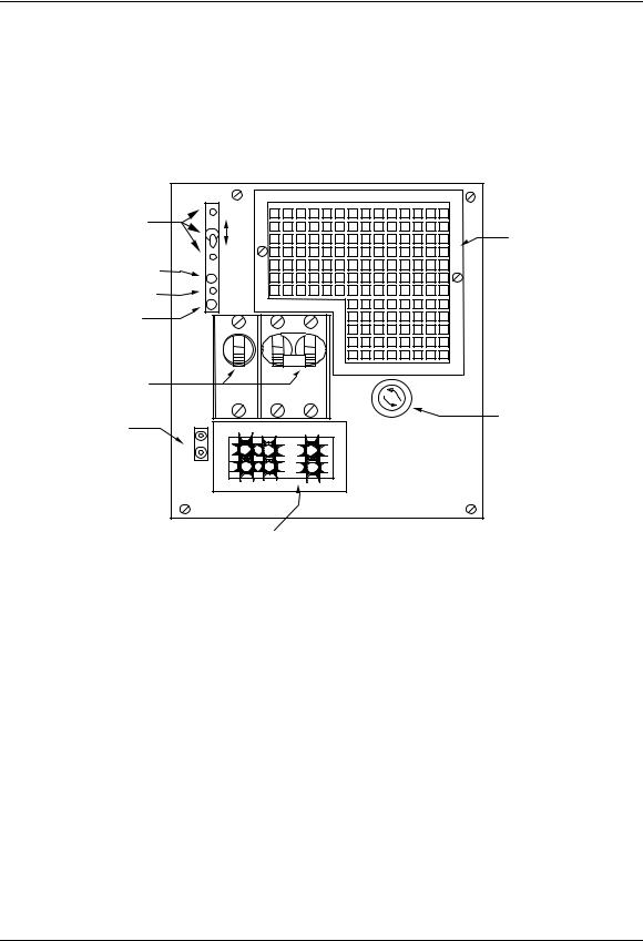
Figures 1 and 2 show the front and rear views of the fully equipped rectifier.
Figure 1 - NT5C06B/C Rectifier (front view)
EQUALIZE |
|
|
|
|
|
/FLOAT |
|
EQL |
|
|
|
SWITCH AND |
|
|
|
|
FILTER |
ADJUST |
|
FLT |
|
|
OPTION |
|
|
|
|
||
FAN ALARM |
|
FAN |
|
|
|
|
|
|
|
|
|
HVSD ADJUST |
|
HVSD |
|
|
|
|
ON/RFA |
|
|
|
|
RECTIFIER |
|
|
|
|
|
OK/FAIL |
DC |
|
|
|
|
CIRCUIT |
|
|
|
|
|
|
|
|
|
|
|
BREAKERS |
|
|
AC |
|
INRUSH |
|
|
|
F1 |
||
|
|
|
|
CURRENT |
|
|
|
|
|
|
|
TEST |
OUTPUT |
. |
3/4A 250V |
|
LIMIT |
|
|
||||
V+ |
|
|
FUSE |
||
POINTS |
|
|
|
||
V- |
LOAD |
|
|
||
|
|
|
|
CURRENT METER
Local float / equalize control
The rectifier is equipped with a momentary Float/Equalize switch. When the switch is held in the EQL position, the rectifier changes to equalize mode and boosts the output voltage to the value set by the EQL potentiometer. Otherwise, the rectifier delivers a float voltage set by the FLT potentiometer.
Indicator lamps
Designation |
Color |
Description |
RFA/ON |
Red |
Rect. Failed or no load current * |
|
Green |
Rectifier operational |
Fan |
Red |
Fan Failed |
UM5C06B / C ( 169-2071-500 ) P0711722 Standard 10.00 May 2001

Operation 23
Rectifier failure alarm (RFA)
The rectifier incorporates facilities for monitoring its operational state and extends a global alarm upon detection of an internal failure or a no load condition (see Note below). When the rectifier operates in parallel with other rectifiers and its output voltage is adjusted lower, the RFA LED will change to RED and an RFA alarm will be sent.
Note: Give an alarm at no load condition only for the following releases or under.
NT5C06BB, BB-1, BB-3, BC |
Rel. 10 |
NT5C06CA, CA-1, CA-3, CA-5 ,CC |
Rel. 10 |
NT5C06CB, CB-1, CB-3, CD |
Rel. 12 |
NT5CO6CE-61(-46) |
Rel. 12 |
Fan failure alarm
A fan failure will activate the fan alarm and inhibit the operation of the rectifier. An RFA will also be issued upon inhibition of the rectifier.
Internal high voltage shut down (HVSD)
The rectifier includes a high voltage monitor. Whenever the rectifier output voltage exceeds a value adjustable from -52 to -59.5 V it shuts down immediately, locks out, and transmits an RFA. This function is not dependent on the output load condition.
Local ON/OFF control (DC and optional AC breakers)
Circuit breakers are used to turn the rectifier ON/OFF locally and disengage it from the DC circuit. The local OFF control overrides the remote control signals.
Inrush current limiting fuse (F1)
A 3/4 A, 250 V fuse is connected in line with the soft start circuitry to protect the input circuitry against high inrush currents in case of an internal failure. On the MPR15E modes NT5C06CB/CD/CE, failure of this fuse during operation will disable the unit. See the “Recommended Replacement Parts” section to order a replacement fuse.
25A Switch Mode Rectifier NT5C06B / C Installation and User Manual
24 Operation
Test points (V+, V-)
Test points allow the user to measure the voltage at the point of regulation, whether the DC breaker is ON or OFF. A 10 K resistor is placed in series with the –48 V lead to prevent short circuits at the jack terminals.
Current meter
A three-digit output current meter, available on the enhanced model, reads the output shunt and displays the value using an integrated logic circuit.
Fan filter option
A fan filter option is available for dusty environments to prevent the dust particles from entering and deteriorating the cooling efficiency of the rectifier. (See the “Recommended Replacement Parts” section to order an air filter kit.)
The maximum operating ambient temperature should be limited to 50°C (122°F) for environments requiring the rectifier air filter.
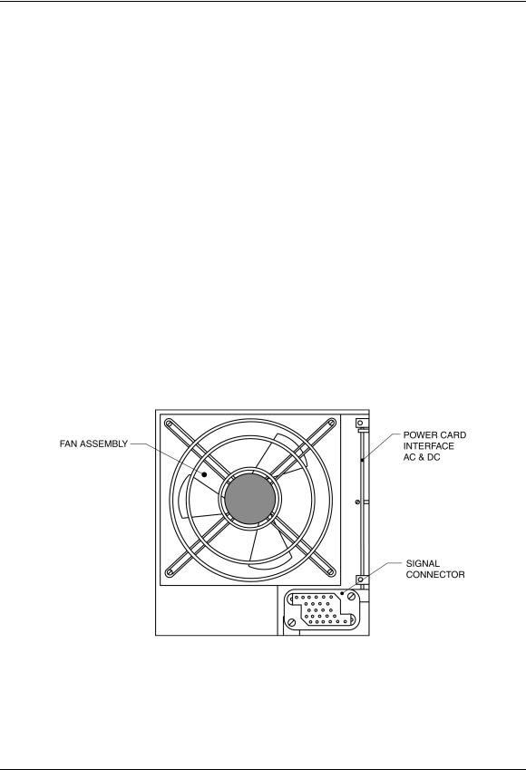
Rear interface
Figure 2 - Rear interface
Fan cooling assembly
The fan cooling assembly ensures adequate cooling of the internal components. This assembly can be replaced in the field. Consult the “Fan Replacement Procedure” section for details.
UM5C06B / C ( 169-2071-500 ) P0711722 Standard 10.00 May 2001

Operation 25
Signal connector
This connector provides control and monitoring signal access to the rectifier. Refer to the “Signal Connections” section for connection details.
Power interface edge connector
The rectifier AC, DC and chassis ground interface is made through the rear edge connector. Refer to the “Rectifier and Controller Interface Connections” section for connection and installation details.
Features
The rectifier provides the following operating, monitoring, measurement and control features:
Operating features
Remote voltage sensing
Provision is made to extend the sensing leads to the battery or to the charge/discharge bus (operation without batteries) of the plant. The opening of either sensing leads will not result in a voltage increase at the rectifier output terminals.
Current limiting
The rectifier will automatically limit the output current to 17.5 to 20 A (MPR15) and 25.5 to 30 A (MPR25). Extended periods of operation in the current limiting mode, and repeated transitions between constant-voltage operation and constant-current operation have no detrimental effect on the performance or service life of the rectifier.
The rectifier is capable of starting when connected across a completely discharged battery without requiring human intervention or operating protection devices.
Transitions from constant-voltage operation to constant-current operation and from constant-current to constant-voltage operation will occur automatically, as determined by the output current. The current limit circuit will continue working in both the float and equalize modes.
Soft start and walk-in
The output current rises from 10% to 90% in 2 seconds (typically).
25A Switch Mode Rectifier NT5C06B / C Installation and User Manual

26 Operation
AC inrush current
The AC current during the turn on sequence of the rectifier, under all input and output conditions specified in this document, will not exceed its full load steady-state value.
Sequential start
The rectifier Temporary Release (TR) leads are available for use with an external sequential start circuit.
Parallel operation
The rectifier is capable of operating in parallel with other rectifiers having similar output slope characteristics.
Discharge of output capacitors
The output capacitors will automatically discharge when the rectifier is disconnected and the AC power has been removed.
Load sharing
Rectifiers connected in parallel and sensing at the same point will share the load with other rectifiers having similar negative output slope characteristics (300 mV drop from zero to full load).
The rectifier will share the load proportionally to its output rating to a precision within +10%.
Monitoring features
Input AC voltage monitor
The rectifier monitors the input voltage and inhibits its operation when the voltage exceeds the specified limits. Refer to the “Summary of Specifications” section, sub section Electric. An RFA is initiated.
The rectifier recovers its normal operation automatically when the specified input voltage is re-established.
Thermal shutdown
The rectifier protects itself against thermal overstress by inhibiting its operation for the duration of the high temperature condition. The RFA alarm is triggered. The rectifier will restart after the temperature has returned to a safe level.
UM5C06B / C ( 169-2071-500 ) P0711722 Standard 10.00 May 2001

Operation 27
Output current monitor
The rectifier monitors the output current. The unit will initiate an RFA alarm when no output current (see Note below) is detected during parallel operation.
Note: Give an alarm at no load condition, only for the following releases or under.
NT5C06BB, BB-1, BB-3, BC |
Rel.10 |
NT5C06CA, CA-1, CA-3, CA-5, CC |
Rel.10 |
NT5C06CB, CB-1, CB-3, CD |
Rel.12 |
NT5CO6CE-61(-46) |
Rel.12 |
Measurement features
Remote rectifier current measurement
The rectifier is equipped with a 50 mV / 25 A shunt connected on the positive lead, near the output terminals. The shunt signal is available on the signal connector (see Figure 3).
Test points (V+, V-)
Voltage jacks are provided for measuring the voltage at the point of regulation.
Control features
Remote ON/OFF control
When a ground signal is applied to the 'Temporary Release' (TR) input, the rectifier inhibits its operation and activates the rectifier's RFA. Upon removal of the remote ground signal the rectifier returns to normal operation.
Remote high voltage shutdown
In addition to the local high voltage shutdown feature, the power plant controller can shut down any rectifier by sending a high voltage shutdown signal, ground (BAT RTN) pulse. The rectifier will shut down if it is supplying more than 10% of its full load rating.
25A Switch Mode Rectifier NT5C06B / C Installation and User Manual

28 Operation
Local/remote high voltage shutdown reset
The rectifier may be reset from an HVSD condition locally, by resetting the AC circuit breaker (if so equipped), the associated AC breaker on the distribution panel, or remotely by applying a ground signal at the HVSDR input of the rectifier provided:
•the 'TR' lead is not activated
•the 'AC' (optional) and 'DC' breakers are closed
Remote equalize control
The rectifier is equipped with remote equalize control. This function is operated by applying a remote ground signal (BAT POS) and returns to normal (Float) operation upon removal of the signal.
Signal connections
The interface connector located at the rear of the rectifier provides control, alarm and monitoring signals. The control inputs are activated by a ground (BAT RTN) signal. The alarm contacts are extended by relays and are isolated from each other, and from the rectifier chassis. All contacts are rated 60 V DC and 0.5 A.
UM5C06B / C ( 169-2071-500 ) P0711722 Standard 10.00 May 2001
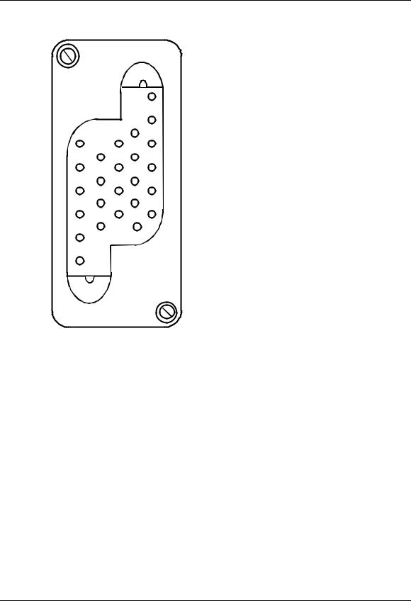
Operation 29
Figure 3 - Signal Connector
|
1 |
- REMOTE EQL |
|
2 |
- SENSING RG + |
|
3 |
- SENSING RC - |
|
4 |
- TEMPORARY RELEASE |
1 |
5 |
- REMOTE HVSD RESET |
6 |
- REMOTE HVSD |
|
|
7 |
- RFA NC |
|
8 |
- Not Connected |
|
9 |
- FAN ALARM NC |
|
10 |
- RFA COMMON |
|
11 |
- FAN ALARM COMMON |
|
12 |
- SHUNT + |
|
13 |
- SHUNT - |
|
14 |
- FAN ALARM NO |
|
15 |
- RFA NO |
|
16 |
- GROUND |
|
17 |
- SENSE COMMON |
|
18 |
- SENSE NC |
|
19 |
- SENSE NO |
|
20 |
- Not Connected |
25 |
21 |
- Not Connected |
|
22 |
- Not Connected |
|
23 |
- Not Connected |
|
24 |
- Not Connected |
|
25 |
- Not Connected |
Connector housing: |
|
AMP 211149-1 |
Crimp type pins (24-20 AWG): |
|
AMP 66103-1 |
PCB solder/wire wrap pins: |
|
AMP 66460-7 |
The 'SENSE' alarm contact closes to indicate that the remote sense leads are open.
The signals normally connected to Astec controllers are indicated below.
25A Switch Mode Rectifier NT5C06B / C Installation and User Manual

30 Operation
Rectifier and controller interface connections
Designation |
Description |
Signal |
RG+/RC- |
Sensing Leads |
battery or |
|
|
charge/discharge bus |
HVSD |
Remote High Voltage |
Bat RTN |
|
Shutdown |
|
HVSDR |
Remote High Voltage |
Bat RTN |
|
Shutdown Reset |
|
TR |
Remote Inhibit |
Bat RTN |
EQ |
Remote Equalize |
Bat RTN |
RFA |
Rectifier Failure Alarm |
Form C contacts |
F.ALM |
Fan Failure Alarm |
Form C contacts |
Shunt (+) and Shunt (-) |
Rectifier Current |
50 mV at 25 A |
UM5C06B / C ( 169-2071-500 ) P0711722 Standard 10.00 May 2001
 Loading...