


 Loading...
Rosemount Analytical
NGA 2000
Software Manual
MLT Analyzer
MLT Analyzer Module
(combined with NGA 2000 platform /
MLT analyzer / TFID analyzer
or customer-developed control unit)
Software Version 3.2.X
2nd Edition 07/98
Catalog No.: 90 003 482


 Managing The Process Better
90003482(2) [NGA-e (MLT-Software 3.2.X)] 07/98

Rosemount Analytical
This Operation Manual includes information about the operation of the instrument.
Information about the additional indications and notes regarding maintenance, troubleshooting and repair are found in the accompanying Maintenance & Operation Manual.
Troubleshooting, component replacement and internal adjustments must be made by qualified service personnel only.
Fisher-Rosemount GmbH & Co does not take responsibility for any omissions or errors in this manual. Any liability for direct or indirect damages, which might occur in connection with the delivery or the use of this manual, is expressly excluded to the extend permitted by applicable law.
This instrument has left the works in good order according to safety regulations.
To maintain this operating condition, the user must strictly follow the instructions and consider the warnings in this manual or provided on the instrument.
Misprints and alterations reserved
©1998 by FISHER-ROSEMOUNT GmbH & Co. (ETC/PAD)
1st Edition: 04/98
2nd Edition: 07/98
Read this operation manual carefully before attempting to operate the analyzer !
For expedient handling of reports of defects, please include the model and serial number which can be read on the instrument identity plate.
Fisher - Rosemount GmbH & Co.
European Technology Center
Industriestrasse 1
D - 63594 Hasselroth • Germany
Phone + 49 (6055) 884-0
Telefax + 49 (6055) 884-209
Internet: http://www.processanalytic.com
90003482(2) [NGA-e (MLT-Software 3.2.X)] 07/98
Contents
1 |
Introduction |
|
1 - |
1 |
|
2 |
Structure of Menus |
2 - |
1 |
||
3 |
Startup and Operation, General Notes and Main Menu |
3 - 1 |
|||
3.1 |
Starting and Initializing ................................................................................... |
3 |
- |
1 |
|
3.2 |
Display and Function...................................................................................... |
3 |
- |
2 |
|
3.3 |
"TAG" and Operating Keys ............................................................................ |
3 |
- |
2 |
|
3.4 |
Lines and Softkey Functionality ..................................................................... |
3 |
- |
3 |
|
3.5 |
Important Functions of the Softkeys............................................................... |
3 |
- |
4 |
|
3.6 |
Entering/Changing of Variables...................................................................... |
3 |
- |
5 |
|
3.7 |
Starting a Function ......................................................................................... |
3 |
- |
6 |
|
3.8 |
Main Menu ..................................................................................................... |
|
3 |
- |
7 |
4 |
Basic Controls and Analyzer Module Calibration |
4 - |
1 |
||
4.1 |
Analyzer Channel Status................................................................................ |
4 |
- |
3 |
|
4.1.1 |
Status Details – |
Failures ............................................................................... |
4 |
- |
5 |
|
– |
Maintenance requests ........................................................ |
4 |
- |
7 |
|
– |
Function controls ................................................................ |
4 |
-11 |
|
|
– |
Measurements/Alarms........................................................ |
4 |
-13 |
|
|
– |
Events................................................................................. |
4 |
-15 |
|
|
– |
Acknowledge and clear failures .......................................... |
4 |
-19 |
|
|
– |
Acknowledge and clear maintenance requests .................. |
4 |
-23 |
|
|
– |
Acknowledge and clear function controls............................ |
4 |
-27 |
|
4.1.2 |
Operational Settings....................................................................................... |
4 |
-31 |
||
4.2 |
Single Component Display - Change of Channel........................................... |
4 |
-33 |
||
4.3 |
Multi Component Display - Change of Channel ............................................. |
4 |
-35 |
||
4.4 |
Calibration Procedure Status ......................................................................... |
4 |
-37 |
||
4.5 |
Zero Calibration.............................................................................................. |
|
4 |
-39 |
|
4.6 |
Span Calibration............................................................................................. |
|
4 |
-43 |
|
4.7 |
Flow Zero Gas................................................................................................ |
|
4 |
-47 |
|
4.8 |
Flow Span Gas............................................................................................... |
|
4 |
-51 |
|
4.9 |
Flow Sample Gas........................................................................................... |
4 |
-55 |
||
4.10 |
Flow Test Gas ................................................................................................ |
|
4 |
-59 |
|
4.11 |
Close all Valves.............................................................................................. |
|
4 |
-63 |
|
90003482(2) [NGA-e (MLT-Software 3.2.X)] 07/98
NGA 2000 |
I |
5 |
Analyzer and I/O-Module Expert Configuration |
5 - |
1 |
|
5.1 |
Analyzer Module Setup |
5 |
- |
3 |
5.1.1 |
Calibration Parameters................................................................................... |
5 |
- |
5 |
|
– Span gases ......................................................................................... |
5 |
- |
6 |
|
– Tolerances .......................................................................................... |
5 |
- |
7 |
|
– Calibration procedure setup ................................................................ |
5 |
- |
9 |
|
– Time controlled calibration .................................................................. |
5 |
-12 |
|
|
– Calibration........................................................................................... |
5 |
-15 |
|
|
– Advanced calibration methods ............................................................ |
5 |
-18 |
|
|
– Zero gases .......................................................................................... |
5 |
-20 |
|
5.1.2 |
Alarm Parameters........................................................................................... |
5 |
-21 |
|
5.1.3 |
Range Parameters ......................................................................................... |
5 |
-25 |
|
|
– Begin and end of ranges..................................................................... |
5 |
-27 |
|
|
– Response times (t90) ........................................................................... |
5 |
-28 |
|
|
– Autoranging control ............................................................................. |
5 |
-29 |
|
5.1.4 |
Cross Interference Compensation.................................................................. |
5 |
-31 |
|
5.1.5 |
Linearization ................................................................................................... |
5 |
-33 |
|
5.1.6 |
Programmable Logic Control (PLC)................................................................ |
5 |
-37 |
|
5.1.7 |
Programmable Calculator ............................................................................... |
5 |
-45 |
|
5.1.8 |
Measurement Display Configuration............................................................... |
5 |
-49 |
|
5.1.9 |
Acknowledgement of Status Reports.............................................................. |
5 |
-52 |
|
5.1.10 |
Concentration Measurement Parameters....................................................... |
5 |
-54 |
|
5.1.11 |
Peak Measurement ........................................................................................ |
5 |
-55 |
|
5.1.12 |
Differential Measurement ............................................................................... |
5 |
-57 |
|
5.1.13 |
Gasflow Setup ................................................................................................ |
5 |
-59 |
|
5.1.14 |
Pressure Compensation ................................................................................. |
5 |
-60 |
|
5.1.15 |
Flow Measurement ......................................................................................... |
5 |
-62 |
|
5.1.16 |
Temperature Measurement ............................................................................ |
5 |
-63 |
|
5.1.17 |
Loading/Saving Configuration Parameters ..................................................... |
5 |
-64 |
|
5.1.18 |
Inputs and Outputs ......................................................................................... |
5 |
-67 |
|
|
– Local SIO ............................................................................................ |
5 |
-68 |
|
|
– Local DIO ............................................................................................ |
5 |
-74 |
|
|
– Signal codes........................................................................................ |
5 |
-75 |
|
5.1.19 |
Delay and Average ......................................................................................... |
5 |
-79 |
|
5.1.20 |
Special Functions ........................................................................................... |
5 |
-81 |
|
5.1.21 |
AK-Protocol Communication .......................................................................... |
5 |
-82 |
|
II |
NGA 2000 |
90003482(2) [NGA-e (MLT-Software 3.2.X)] 07/98
5.2 |
I/O Module Controls |
5 -83 |
|||
5.2.1 |
SIO Module |
5 -84 |
|||
5.2.2 |
DIO Module(s) |
5 -93 |
|||
5.3 |
I/O Module Setup |
5 -99 |
|||
6 |
System Configuration |
6 - |
1 |
||
6.1 |
Diagnostic Menus........................................................................................... |
6 |
- |
3 |
|
|
6.1.1 |
Control Module Diagnostics................................................................. |
6 |
- |
4 |
|
6.1.2 |
Analyzer Module Diagnostics .............................................................. |
6 |
- |
5 |
6.2 |
Date and Time................................................................................................ |
6 |
- |
6 |
|
6.3 |
Security Codes............................................................................................... |
6 |
- |
7 |
|
6.4 |
Network Module Binding ................................................................................ |
6 |
- |
9 |
|
6.5 |
System Reset................................................................................................. |
6 |
-11 |
||
6.6 |
System Modules............................................................................................. |
6 |
-12 |
||
7 |
Display Controls |
7 - |
1 |
||
Index
Supplement: System Calibration
90003482(2) [NGA-e (MLT-Software 3.2.X)] 07/98
NGA 2000 |
III |
IV |
NGA 2000 |
90003482(2) [NGA-e (MLT-Software 3.2.X)] 07/98

1 Introduction
This software manual describes step by step how to operate successfully with the ½ 19" and 19" MLT analyzer module and analyzer of the 


 NGA 2000 Series. Chapter two shows the structure of the MLT software menus. Chapter three describes the display and the keyboard of the analyzer. Chapter four describes the basic controls with detailed illustrations. So you can easily compare the actual display of the analyzer module with the illustrations of the manual.
Chapter five describes the expert configurations of the analyzer module and of the Input/ Output Modules (I/O modules). Chapter six describes the system configuration. The layout of both chapters is not as detailed as in chapter four. Normally, the way to a certain menu of the MLT software is described with the software catchwords you have to press to reach this menu. You will find the illustration of the corresponding LCD screen at the end of the catchword listing. After that you can read the meaning of the functions and variables of each expert or system configuration menu.
Some contents of the expert configurations are not important for each customer. It depends on the configuration of your NGA 2000 system, relative to the following components:
♦ Control Module |
CM |
||||||
♦ Analyzer Module |
AM |
||||||
♦ Input/Output Modules |
I/O's (SIO =Standard I/O, DIO = Digital I/O, |
||||||
|
|
|
|
|
|
|
|
|
|
|
System Auto Calibration I/O, Analog Output with 3 Alarms I/O, |
||||
|
|
|
Auto Calibration I/O) |
||||
You can distinguish the following system units and SIO/DIO configurations:
System Unit |
SIO/DIO-Configuration |
Section |
|
Page |
|||
|
|
||
MLT analyzer module (AM): |
Þ 1 local SIO and 1 local DIO can be |
|
|
· without front panel, |
installed in the MLT analyzer |
|
|
module |
|
||
i.e. without control unit |
5.1.18 |
||
Þ SIO and DIO can be configured |
|||
· can be combined with a platform, |
|||
p. 5-67 |
|||
for the channels of the analyzer |
|||
an MLT analyzer, a TFID analyzer |
|||
|
|||
module only |
|
||
or a customer developed control |
|
||
|
|
||
unit |
|
|
|
Platform (CM Software): |
Þ 1 SIO and up to 4 DIO's can be |
|
|
· Control unit with front panel |
installed in the platform (CM I/O) |
5.2 |
|
Þ SIO and DIO can be configured |
|||
· Without measurement channels |
p. 5-83 |
||
for all channels combined with the |
|||
|
|
||
|
platform |
|
|
MLT analyzer (CM and MLT AM |
Þ 1 SIO and 1 DIO can be installed |
|
|
software): |
in the MLT analyzer (CM I/O) |
|
|
· Analyzer with front panel |
Þ SIO and DIO can be configured |
5.2 |
|
|
· CM and AM software in the same |
for all channels combined with the |
p. 5-83 |
|
MLT analyzer |
|||
analyzer, |
|||
|
|||
|
|
||
i.e. all functions of the control unit |
|
|
|
and of the AM are combined in one |
|
|
|
controller board |
|
|
90003482(2) [NGA-e (MLT-Software 3.2.X)] 07/98
NGA 2000 |
1 - 1 |
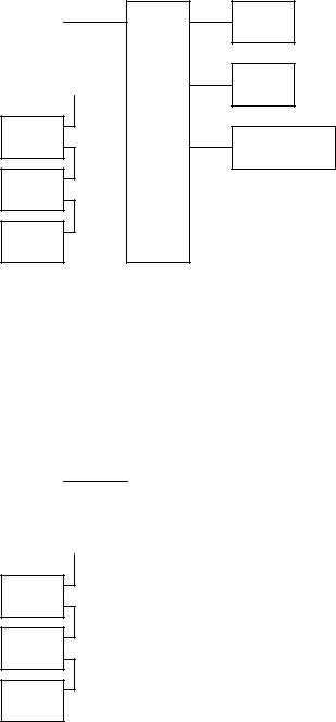
The following illustrations shall make plain the connection between the hardware configuration and the software setup of the modules:
NGA 2000 System via Platform
|
Local |
|
Analyzer |
||
|
I/O's |
Modules (AM's) |
|||
|
|
|
|
|
|
(see 5.1.18) |
SIO |
|
TFID |
|
|
|
|
|
|||
|
|
|
|
||
|
DIO |
|
|
|
|
|
|
|
|
|
|
(see 5.1.18) |
SIO |
|
MLT |
|
|
|
|
|
|||
|
|
|
|
||
|
DIO |
|
|
|
|
(additional
CLD
manuals)
(additional
PMD
manuals)
(additional
FID
manuals)
Control
Module (CM)
Platform
I/O
Modules
1 SIO (see 5.2.1)
4 DIO's (see 5.2.2)
max.
Other I/O's
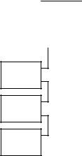
NGA 2000 System via MLT Analyzer
|
Local |
|
Analyzer |
||
|
I/O's |
Modules (AM's) |
|||
|
|
|
|
|
|
(see 5.1.18) |
SIO |
|
MLT |
|
|
|
|
|
|||
|
|
|
|
||
DIO |
|
|
|
||
|
|
|
|
|
|
|
|
|
|
||
|
|
|
|
|
|
(see 5.1.18) |
SIO |
|
TFID |
|
|
|
|
|
|||
|
|
|
|
||
DIO |
|
|
|
||
|
|
|
|
|
|
|
|
|
|
|
|
(additional
CLD
manuals)
(additional
PMD
manuals)
(additional
FID
manuals)
|
Control |
System I/O |
|
|||
Module (CM) |
|
Modules |
|
|||
|
|
|
|
|
|
(see 5.2.1) |
|
AnalyzerMLT |
|
|
1 SIO |
|
|
|
|
|
|
|||
|
|
|
|
|
|
|
|
|
|
|
|
|
|
|
|
|
1 DIO |
|
(see 5.2.2) |
|
|
|
|
|
|
||
|
|
|
|
|
|
|
|
|
|
|
|
|
|
1 - 2 |
NGA 2000 |
90003482(2) [NGA-e (MLT-Software 3.2.X)] 07/98
1 Introduction
NGA 2000 System via TFID Analyzer
|
Local |
|
Analyzer |
||
|
I/O's |
Modules (AM's) |
|||
|
|
|
|
|
|
(see 5.1.18) |
SIO |
|
TFID |
|
|
|
|
|
|||
|
|
|
|
||
|
DIO |
|
|
|
|
|
|
|
|
|
|
(see 5.1.18) |
SIO |
|
MLT |
|
|
|
|
|
|||
|
|
|
|
||
DIO |
|
|
|
||
|
|
|
|
|
|
|
|
|
|
|
|
(additional
CLD
manuals)
(additional
PMD
manuals)
(additional
FID
manuals)
|
Control |
System I/O |
|
|||
Module (CM) |
|
Modules |
|
|||
|
|
|
|
|
|
(see 5.2.1) |
|
AnalyzerTFID |
|
|
1 SIO |
|
|
|
|
|
|
|||
|
|
|
|
|
|
|
|
|
|
|
|
|
|
|
|
|
1 DIO |
|
(see 5.2.2) |
|
|
|
|
|
|
||
|
|
|
|
|
|
|
|
|
|
|
|
|
|
90003482(2) [NGA-e (MLT-Software 3.2.X)] 07/98
NGA 2000 |
1 - 3 |
1 - 4 |
NGA 2000 |
90003482(2) [NGA-e (MLT-Software 3.2.X)] 07/98
07/98 X)].2.3 Software-(MLT e-[NGA 90003482(2)
2000 NGA
1 - 2
|
|
|
|
|
Main Menu |
|
Section 3.8 |
|
|||||
|
|
|
|
|
|
|
|
|
|
|
|
|
|
|
|
|
|
|
|
|
|
|
|
|
|
|
|
|
|
|
|
|
|
|
|
|
|
|
|
|
|
Analyzer module |
|
Analyzer and I/O- |
|
System configuration |
|
|
calibration & basic |
|
module expert |
|
|
Display controls... |
|
|
|
and diagnostics... |
|
|||
controls... (AM) |
|
configuration... |
|
|
|
|
|
|
|
|
|
||
Section 4 |
|
Section 5 |
|
Section 6 |
|
Section 7 |
- Calibration procedure |
- Analyzer module |
- System calibration... (CM) |
status... |
controls... (AM) |
- Diagnostic menus... |
- Zero calibration of all |
- I/O module controls... |
(AM, CM, I/O's: SIO, DIO |
ranges |
(I/O's: SIO, DIO) |
and other I/O's) |
- Span calibration of the |
- Analyzer module setup... |
- Date and time... (CM) |
current range |
(AM) |
- Security codes... |
- Current gas valve setting: |
- I/O module setup... |
(Lock of each level) |
- Zero gas flow |
(Other micro processor |
- Network module binding... |
- Span gas flow |
controlled I/O's) |
(AM, CM, I/O's: SIO, DIO |
- Sample gas flow |
|
and other I/O's) |
- Test gas flow |
|
- System reset... (CM) |
- Closing all valves |
|
- System modules... (CM) |
|
|
- System tag (CM) |
Notes: |
|
|
-Display controls of the front panel LCD
-Front panel control (number of digits)
-Auxiliary lines (for the
single component display)
*Menu lines ending with three points (...) are followed by submenus with further functions and set-ups.
* All set-ups in the menu "Basic controls" are valid for the analyzer module (AM).
*At each menu point of the "Expert configuration" and "System configuration" you can find which functionality will be set up: AM (Analyzer Module), CM ( Control Module), I/O ( Input-/Output Module).
Menus of Structure 2
2 - 2 |
NGA 2000 |
90003482(2) [NGA-e (MLT-Software 3.2.X)] 07/98
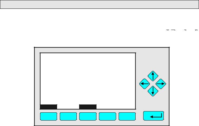
3 Startup and Operation, General Notes and Main Menu
3.1 Starting and Initializing
After switching on the MLT analyzer or analyzer module (in a platform or part of a NGA network), the initialization procedure will be performed. A self control of the analyzer modules or the analyzer is running. You can see a sequence of several displays. They show the status of initialization, revision notes of the MLT software and the 


 tag:
tag:
(C) 1998 FISHER-ROSEMOUNT Analytical |
||||
|
NGA-2000 Control Module/Version 3.2.1 |
|
||
|
|
Initializing Network |
|
|
|
Initializing network interface |
|
||
LCDReset |
|
Abort |
|
|
F1 |
F2 |
F3 |
F4 |
F5 |
If you press the F1 key during the initializing, you will reset the LCD brightness and contrast to factory settings (see also section 7). Pressing the F3 key will abort the network initializing. Then you will have no connection to any analyzer module. Only the menus of the platform will be available.
At the end of the initializing procedure you can see the single component display of channel one (see illustration on next page). It is the origin to all the other channels, menus and submenus.
The instructions of the basic controls (chapter four) are all beginning with the single component display. The actual display might differ from the shown one because the customer can configure it according to his requirements (see section 5.1.8 p. 5-49 and section 7).
90003482(2) [NGA-e (MLT-Software 3.2.X)] 07/98
NGA 2000 |
3 - 1 |
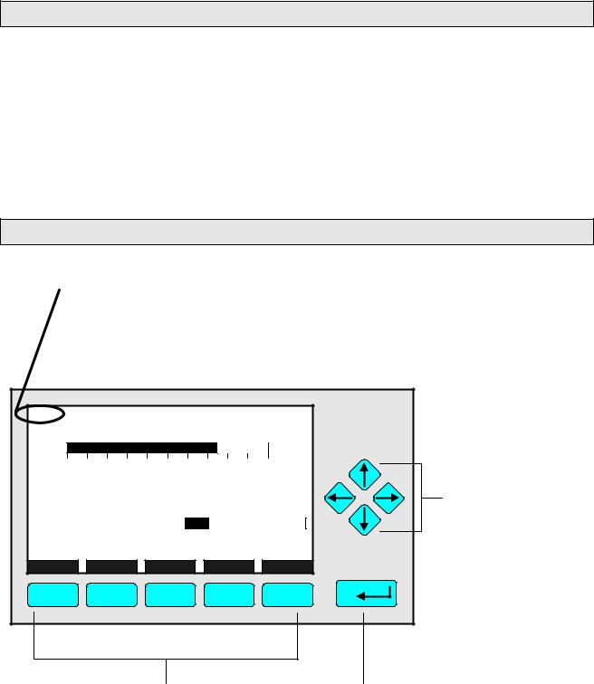
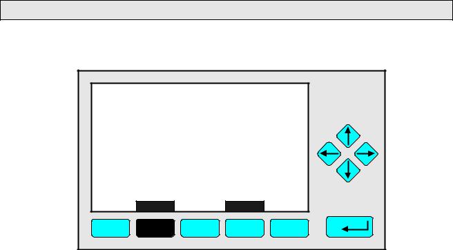
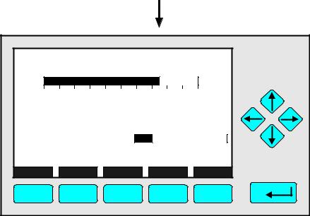
3.2 Display and Function
The LCD screen shows all measurement values of the analyzer and all customer instructions. You can operate with five function keys, four arrow keys (cursors) and the enter key. The function of each key depends on:
♦the type of analyzer/analyzer module used
♦the optional auxiliary modules (e.g. I/O boards) used
♦the individual menu displayed
In case of power failure all customer specific module parameters are saved by a batterypowered buffer.
3.3 "TAG" and Operating Keys
At the top left of each menu page you will find the tag of the current channel.
Typical tags:
♦ MLT/CH1/R1: MLT Analyzer or Analyzer Module / CHannel 1 / Range 1 ♦ TFID-R1: Thermo FID Analyzer or Analyzer Module - Range 1
In this manual you will find normally "TAG" as general name. But in the specific MLT menu pages you will find "MLT".
TAG |
|
|
|
|
|
|
37.50 |
|
|
|
ppm CH4 |
||
0.00 |
|
|
Range: 1 |
50.00 |
||
Failures: |
|
|
No |
|
|
|
Maintenance-Requests: |
No |
|
|
|
||
Temperature: |
|
20.0 C |
0.0 |
|
100.0 |
|
Operation: |
|
Ready |
|
|
|
|
Display |
Status... |
|
Main... |
|
Channel |
Calib... |
F1 |
F2 |
|
F3 |
|
F4 |
F5 |
Cursor keys:
− -key / ↓ -key:
♦Line up / line down within the same menu
♦Alteration of numbers, variables or digits
← -key / → -key:
♦Moving back/forwards between the pages of a menu
♦Selection of digits
Function Keys:
♦keys without defined functions
♦The current function depends on the menu selected
♦The softkey legend is shown on the display above the key
Enter Key:
♦To confirm a previously entered value (variable)
♦To start a selected function (Alternative: → -key)
♦To go into a menu (via menu line)
3 - 2 |
NGA 2000 |
90003482(2) [NGA-e (MLT-Software 3.2.X)] 07/98
3 Startup and Operation, General Notes and Main Menu
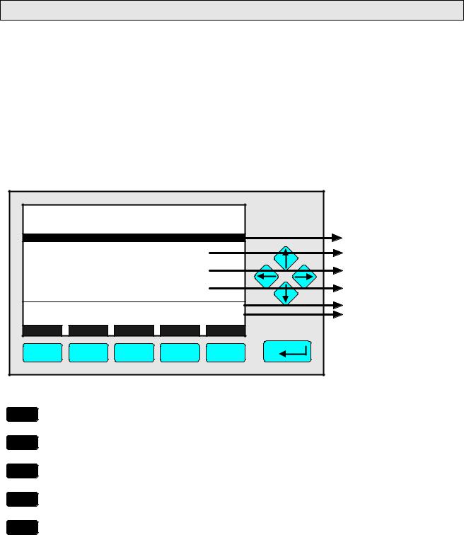
3.4 Lines and Softkey Functionality
Lines can be selected by the ↓ -key or the − -key. The selected line is displayed white on black. You have four different types of lines in the menu:
Menu line... / Menu Softkey...
♦Line/Softkey lettering ending with three dots.
♦You will go to a submenu/further menu by pressing the softkey resp. by pressing the
8 -key or the → -key in the menu line.
Function line / Function Softkey !
♦Line/Softkey lettering ending with an exclamation-mark.
♦You will start a function (e.g. calibration) by pressing the softkey resp. by pressing the 8 -key or the → -key in the function line.
Line of variables:
♦Line ending with a colon.
♦Display of module parameters (variables).
♦Some parameters can be changed (e.g. begin of range), some parameters display only a status (e.g. temperature) and cannot be changed. These variables will be displayed below a line within the menu.
Text line
♦Line without any punctuation marks.
♦Only display of informations.
The following illustrations shall make plain the functionalities of lines and softkeys described above:
|
|
|
|
|
|
|
|
|
|
|
|
|
|
|
|
|
|
|
|
|
|
|
|
|
|
|
|
|
|
|
|
|
TAG |
|
|
|
|
|
|
|
|
|
|
37.50 ppm |
|
|
|
|
|
|
|
||
|
|
|
|
|
|
|
|
|
-- Analyzer Module Calibration -- |
|
|
|
|
|
|
|
|
|
|
|||||||
Menu Line |
|
|
|
|
|
|
|
|
|
|
|
|
|
|
|
|
|
|
||||||||
|
Calibration procedure status... |
|
|
|
|
|
|
|
|
|
|
|
|
|
||||||||||||
|
|
|
|
|
|
|
|
|
|
|
|
|
|
|
|
|
||||||||||
Function Lines |
|
|
|
|
|
Start zero calibration procedure ! |
|
|
|
|
|
|
|
|
|
|
|
|
|
|||||||
|
|
|
|
Start span calibration procedure ! |
|
|
|
|
|
|
|
|
|
|
||||||||||||
|
|
|
|
|
|
|
|
|
|
|
|
|
|
|
|
|||||||||||
|
|
|
|
|
|
|
|
|
|
|
|
|
|
|
|
|
|
|
|
|
|
|
|
|
||
|
|
|
|
|
|
|
|
|
|
|
|
|
|
|
|
|
|
|
||||||||
|
|
|
|
|
|
Time & Date: |
|
|
|
12:50:55 June 16, 1998 |
|
|
|
|
|
|
|
|||||||||
Lines of Variables |
|
|
|
Valve position: |
|
|
|
|
|
|
Samplegas |
|
|
|
|
|
|
|
||||||||
|
|
|
Expected zero gas: |
|
|
|
|
|
|
0.00 ppm |
|
|
|
|
|
|
|
|||||||||
(These here cannot |
|
|
Expected span gas: |
|
|
|
|
|
|
50.00 ppm |
|
|
|
|
|
|
|
|||||||||
be changed) |
|
|
Span gas name: |
|
|
|
|
|
|
|
Methane |
|
|
|
|
|
|
|
||||||||
|
|
|
|
|
|
|
|
|
|
|
|
|
|
|
|
|
|
|
|
|
|
|||||
|
Measure |
|
Status... |
|
Channel |
|
Back... |
|
Valves... |
|
|
|
|
|
|
|
||||||||||
|
|
|
|
|
|
|
|
|
|
|
|
|
|
|
|
|
||||||||||
|
|
|
|
|
|
|
|
|
|
|
|
|
|
|
|
|
|
|
|
|
|
|||||
|
|
|
|
|
|
F1 |
|
F2 |
|
F3 |
|
F4 |
F5 |
|
||||||||||||
|
|
|
|
|
|
|
|
|
|
|
|
|
|
|
|
|
|
|
|
|
|
|
|
|
|
|
90003482(2) [NGA-e (MLT-Software 3.2.X)] 07/98
NGA 2000 |
3 - 3 |
Text Line |
|
|
|
|
|
|
|
|
|
|
|
|
|
|
|
|
|
|
|
|
|
|
|
|
|
|
|
TAG |
|
-- Calibration Procedure Status |
|
|
37.50 ppm |
|
|
|
|
|
|
|
|||||||||||
|
|
|
|
|
|
|
|
|
|
|
|
||||||||||||||
|
|
|
|
|
|
|
|
|
|
|
|
|
|
|
|
|
|
||||||||
|
|
|
Procedure status: |
|
|
|
|
|
|
|
|
Ready |
|
|
|
|
|
|
|
||||||
|
|
|
Remaining procedure time: |
|
|
|
|
|
|
|
0 s |
|
|
|
|
|
|
|
|||||||
|
|
|
Current/expected gas flow: |
|
|
|
Samplegas |
|
|
|
|
|
|
|
|||||||||||
|
|
|
|
|
|
|
|
|
|
|
|
|
|||||||||||||
|
|
|
Concentration in span gas units: |
|
|
|
37.50 ppm |
|
|
|
|
|
|
|
|||||||||||
|
|
|
----------------------Last zero calibration: |
|
Results |
---------------------- |
|
|
|
|
Success |
|
|
|
|
|
|
|
|||||||
|
|
|
|
|
|
|
|
|
|
|
|
|
|
|
|
|
|
||||||||
|
|
|
Last span calibration: |
|
|
|
|
|
|
|
|
Success |
|
|
|
|
|
|
|
||||||
|
|
|
Last zero calibration was: |
Fri 05 - 29 - 1998 13:32:06 |
|
|
|
|
|
|
|
||||||||||||||
|
|
|
Last span calibration was: |
Fri 05 - 29 - 1998 13:37:23 |
|
|
|
|
|
|
|
||||||||||||||
|
|
|
Successful zero+span calibrated ranges: |
1+2+3+4 |
|
|
|
|
|
|
|
||||||||||||||
|
|
|
|
|
|
|
|
|
|
|
|
|
|
|
|
|
|
|
|
|
|
|
|
|
|
|
|
|
Measure |
|
Cancel ! |
|
|
... |
|
Back |
|
|
More... |
|
|
|
|
|
|
|
|||||
|
|
|
|
|
|
|
|
|
|
|
|
|
|
|
|
|
|
|
|
||||||
|
|
|
F1 |
|
F2 |
F3 |
|
F4 |
|
|
F5 |
|
|||||||||||||
|
|
|
|
|
|
|
|
|
|
|
|
|
|
|
|
|
|
|
|
|
|
|
|
|
|
|
|
|
|
|
|
|
|
|
|
|
|
|
|
|
|
|
|
|
|
|
|
|
|
|
|
|
|
|
|
|
|
|
|
|
|
|
|
|
|
|
|
|
|
|
|
|
|
|
|
|
|
Function Softkey |
Menu Softkeys |
3.5 Important Functions of the Softkeys
Display
♦Change from the single component display to the multi component display.
♦F1 in the single component display.
Measure
♦Change from all menus and submenus to the single component display of the channel selected.
♦F1.
Status (see section 4.1 p. 4-3!)
♦Change to the menu "Analyzer Channel Status":
Display of the most important parameters and information about the status of the current channel or module.
♦If available: F2.
Main (see section 3.8 p. 3-7!)
♦Change from the single component display to the main menu.
♦F3 in the single component display.
Channel
♦Scrolling through the channels in the same menu. In the main menu and the single component display you can move among all channels of the connected analyzers and analyzer modules. In the submenus you can only move among the channels of the current analyzer or analyzer modules.
♦If available: F3 (F4 in the single component display).
3 - 4 |
NGA 2000 |
90003482(2) [NGA-e (MLT-Software 3.2.X)] 07/98

3 Startup and Operation, General Notes and Main Menu
Lock
♦Lock of all three operation levels from the main menu, if a security code is activated in the system configuration level (see section 6.3 p. 6-7).
♦F4 in the main menu.
Calib (see section 4.4 p. 4-37 and 5.1.1 p. 5-15!)
♦Change from the single component display to the menu "Analyzer module calibration".
♦F5 in the single component display.
MFG Data (see section 3.8 p. 3-7/8!)
♦Change from the main menu to the menu "Module Manufacturing Data": Further submenus are available with informations about the control module and
analyzer module data, such as address of the manufacturer, serial number of the modules or the software and hardware revisions.
♦F5 in the main menu.
Back
♦Moving back to the last menu page selected (Alternative: ← -key) or reset of a changed but not confirmed parameter to the former value.
♦If available: F4 for moving back, F2 for reset.
More
♦Changing to a further menu page.
♦If available: F5.
3.6 Entering/Changing of Variables
8 -key
♦If you have already selected a line of variables (displayed white on black) and press the 8 -key, only the parameter will be selected and can be changed.
If you press the 8 -key again, the new value will be confirmed.
− -key / ↓ -key
♦Function depends on the variable selected: - Changing the parameter values
-Scrolling among variables selected
-Changing of digits or characters
♦Increasing or decreasing of numbers.
← -key / → -key
♦Selection of digits within a number.
♦For some variables you can change the quantity of digits or characters.
90003482(2) [NGA-e (MLT-Software 3.2.X)] 07/98
NGA 2000 |
3 - 5 |
3.7 Starting a function
If you press the 8 -key or the → -key in a function line, you will be asked to confirm the order in the following way:
TAG |
|
|
|
37.50 ppm |
|
-- Confirmation Required -- |
|
||
|
Do you really want to do this ?? |
|
||
|
Press "Yes" or "Back..." |
|
||
|
Yes |
|
Back... |
|
F1 |
F2 |
F3 |
F4 |
F5 |
♦If you will press the F2 key, the function will start immediately.
♦If you will press the F4 key, you will go back to the last menu page.
Note: If you don't want to be asked before the start of each function, you can configure it in the menu "Measurement Display Configuration" in the expert configuration level (see section 5.1.8 p. 5-49). Select "No" in the line "Display confirmation menus". Then, each function will start directly after the order is done and no confirmation will be required.
3 - 6 |
NGA 2000 |
90003482(2) [NGA-e (MLT-Software 3.2.X)] 07/98
3 Startup and Operation, General Notes and Main Menu
3.8 Main Menu
If you press the F3 key (Main...) or the → -key in any single component display, you will change to the "Main Menu". From there you can change to all operating levels of your MLT analyzer or analyzer module to set up and control the parameters of measurement, calibration and data transfer !
Via the F5 key (MFG Data) you can change to several submenus, where you will find a lot of important data about the control module (MLT analyzer or platform) and the analyzer module, such as service address or serial number !
Ramifications from the Main Menu:
TAG |
|
|
|
95.00 ppm |
|
|
|
-- Main Menu -- |
|
|
|
Analyzer module calibration & basic controls... |
|
See chapter 4 ! |
|||
Analyzer and I/O-module expert configuration... |
|
See chapter 5 ! |
|||
System configuration and diagnostics... |
|
See chapter 6 ! |
|||
Display controls... |
|
|
|
See chapter 7 ! |
|
Time & Date: |
|
14:01:45 25 May 1998 |
To setup see 6.2 p. 6-6 |
||
System tag: |
|
|
Fisher-Rosemount |
Factory Setting |
|
Measure |
Status... |
Channel |
Lock... |
MFG Data |
|
F1 |
F2 |
F3 |
F4 |
F5 |
|
F1
F2
F3
F4
F5
Changing to the single component display of the |
+ Section 3.1 p. 3-1/2 ! |
current channel |
|
Changing to the menu "Analyzer Channel Status" of |
+ Section 4.1 p. 4-3 ! |
the current channel |
|
Scrolling through all channels of the connected |
+ See channel tag ! |
analyzers and analyzer modules |
|
Lock of any operating level by security code |
+ Section 6.3 p. 6-7 ! |
Changing to the menu "Module Manufacturing Data" |
+ See next pages ! |
90003482(2) [NGA-e (MLT-Software 3.2.X)] 07/98
NGA 2000 |
3 - 7 |

Ramifications from the menu "Module Manufacturing Data":
1. Control module data:
TAG |
|
|
|
95.00 ppm |
|
-- Module Manufacturing Data -- |
|
||
Control module data... |
|
|
|
|
Analyzer module data... |
|
|
|
|
Measure |
|
<<< |
Back... |
>>> |
F1 |
F2 |
F3 |
F4 |
F5 |
TAG |
|
|
|
95.00 ppm |
(C) Copyright Fisher-Rosemount Analytical Inc., 1998
Manufactured by: Rosemount Analytical Inc. 4125 East La Palma Avenue Anaheim, CA 92807-1802 /USA Tel: (714) 986-7600
FAX: (714) 577-8739
Measure |
|
|
Back... |
|
F1 |
F2 |
F3 |
F4 |
F5 |
2. Analyzer module data:
TAG |
|
|
|
95.00 ppm |
|
-- Module Manufacturing Data -- |
|
||
Control module data... |
|
|
|
|
Analyzer module data... |
|
|
|
|
Measure |
|
<<< |
Back... |
>>> |
F1 |
F2 |
F3 |
F4 |
F5 |
TAG |
95.00 ppm |
(C) Copyright Fisher-Rosemount GmbH & Co, 1998
Manufactured by:
Fisher-Rosemount GmbH & Co
Industriestrasse 1
D-63594 Hasselroth / Germany
Tel. (+49) 6055 884-0
FAX. (+49) 6055 884-209
Measure |
|
Or... |
|
Back... |
|
More... |
F1 |
F2 |
F3 |
F4 |
F5 |
TAG |
|
|
|
95.00 ppm |
|
-- Control Module Version Information -- |
|||
Serial number: |
|
|
CM 4711 |
|
Manufacturing date: |
|
|
14.05.1998 |
|
Hardware revision: |
|
|
ACU02 R: 3.2.2 |
|
Software revision: |
|
|
3.2.1/P001 |
|
Revision date: |
|
|
May 29 1998 |
|
Revision time: |
|
|
12:35:00 |
|
Phrase dictionary version: |
|
P001/1 |
||
Language: |
|
|
English |
|
Measure |
|
|
Back... |
|
F1 |
F2 |
F3 |
F4 |
F5 |
TAG |
|
|
|
95.00 ppm |
(C) Copyright Fisher-Rosemount GmbH & Co, 1998
Manufactured by:
Fisher-Rosemount GmbH & Co
Industriestrasse 1
D-63594 Hasselroth / Germany
Tel. (+49) 6055 884-0
FAX. (+49) 6055 884-209
Measure |
|
|
Back... |
More... |
F1 |
F2 |
F3 |
F4 |
F5 |
|
|
|
|
|
|
|
|
|
|
|
|
|
|
|
|
|
|
|
|
|
|
TAG |
|
|
|
|
|
|
|
|
|
95.00 ppm |
|
|
|
|
|
|
|
||
|
|
|
-- Analyzer Module Version Information -- |
|
|
|
|
|
|
|
||||||||||
|
Serial number: |
|
|
|
|
|
|
AM 4712 |
|
|
|
|
|
|
|
|||||
|
Manufacturing date: |
|
|
|
|
14.05.1998 |
|
|
|
|
|
|
|
|||||||
|
Hardware revision: |
|
|
|
ACU02 R: 3.2.2 |
|
|
|
|
|
|
|
||||||||
|
Software revision: |
|
|
|
|
3.2.1 / P001 |
|
|
|
|
|
|
|
|||||||
|
Revision date: |
|
|
|
|
May 29 1998 |
|
|
|
|
|
|
|
|||||||
|
Revision time: |
|
|
|
|
12:41:18 |
|
|
|
|
|
|
|
|||||||
|
|
|
|
|
|
|
|
|
|
|
|
|
|
|
|
|
|
|
|
|
|
Measure |
|
|
|
|
|
Back... |
|
|
More... |
|
|
|
|
|
|
|
|||
|
|
|
|
|
|
|
|
|
|
|
|
|
|
|
|
|||||
|
F1 |
F2 |
F3 |
F4 |
|
F5 |
|
|||||||||||||
|
|
|
|
|
|
|
|
|
|
|
|
|
|
|
|
|
|
|
|
|
|
|
|
|
|
|
|
|
|
|
|
|
|
|
|
|
|
|
|
|
|
|
|
TAG |
|
|
|
|
|
|
|
|
|
95.00 ppm |
|
|
|
|
|
|
|
|||
|
|
|
|
-- Hardware Configuration -- |
|
|
|
|
|
|
|
|
|
|
|
||||||
|
Measurement system: |
|
|
|
|
|
PSV-System |
|
|
|
|
|
|
|
|||||||
|
RAM-memory: |
|
|
|
|
242748 Bytes |
|
|
|
|
|
|
|
||||||||
|
Local SIO module installed: |
|
|
|
|
Enabled |
|
|
|
|
|
|
|
||||||||
|
Serial interface adaptor: |
|
|
|
|
RS-232 |
|
|
|
|
|
|
|
||||||||
|
Heater installed: |
|
|
|
|
|
|
|
|
No |
|
|
|
|
|
|
|
||||
|
Local DIO module installed: |
|
|
2 |
|
|
|
|
|
|
|
||||||||||
|
Sensor system revision: |
|
|
|
|
|
|
|
|
|
|
|
|
|
|
|
|
||||
|
|
|
|
|
|
|
|
|
|
|
|
|
|
|
|
|
|
|
|
|
|
|
Measure |
|
|
|
Channel |
|
Back... |
|
|
|
|
|
|
|
|
|
|
|
|||
|
|
|
|
|
|
|
|
|
|
|
|
|
|
|
|
||||||
|
F1 |
F2 |
F3 |
F4 |
|
F5 |
|
||||||||||||||
|
|
|
|
|
|
|
|
|
|
|
|
|
|
|
|
|
|
|
|
|
|
3 - 8 |
NGA 2000 |
90003482(2) [NGA-e (MLT-Software 3.2.X)] 07/98
4 Basic Controls and Analyzer Module Calibration
In the chapter "Basic Controls and Analyzer Module Calibration" the most important measurement and calibration functions of your MLT analyzer or analyzer module are described.
All steps are figured with detailed illustrations and operation instructions. In the left column you can see display and keyboard of the NGA front panel. The keys you have to press are illustrated in black. In the right column you can read the instructions and notes. All instructions will begin with any single component display and will end with the corresponding single component display after the setups are done. So you can easily compare the actual display of the analyzer or analyzer module with the illustrations of the manual.
Example: You want to change from the single component display of channel 1(CO2) to the single component display of channel 2 (CO).
∙Picture one shows the starting situation: single component display of CO2.
∙Picture two shows the result you get if you press the F4 key (Channel): single component display of CO.
Left column: |
Right column: |
Display and keyboard |
Instructions and notes |
MLT25/CH1/R2 |
|
|
|
|
|
|
2.50 |
|
|
|
%CO2 |
||
0 |
|
|
Range: 2 |
|
5.00 |
|
Temperature: |
|
25.0 C |
0.0 |
|
100.0 |
|
Maintenance-Requests: |
No |
|
|
|
||
Any_Alarms: |
|
No |
|
|
|
|
Operation: |
|
Ready |
|
|
|
|
Display |
Status... |
|
Main... |
|
Channel |
Calib... |
F1 |
F2 |
|
F3 |
|
F4 |
F5 |
MLT25/CH2/R2 |
|
|
|
|
|
|
95.00 |
|
|
|
ppm CO |
||
0 |
|
|
Range: 2 |
|
250 |
|
Temperature: |
|
25.0 C |
0.0 |
|
100.0 |
|
Maintenance-Requests: |
No |
|
|
|
||
Any_Alarms: |
|
No |
|
|
|
|
Operation: |
|
Ready |
|
|
|
|
Display |
Status... |
|
Main... |
|
Channel |
Calib... |
F1 |
F2 |
|
F3 |
|
F4 |
F5 |
ÞChange to the single component display of another channel
F4
Press
Example:
Changing from
CO2 (Channel 1) to
CO (Channel 2)
ÞNext instruction or step
90003482(2) [NGA-e (MLT-Software 3.2.X)] 07/98
NGA 2000 |
4 - 1 |
4 - 2 |
NGA 2000 |
90003482(2) [NGA-e (MLT-Software 3.2.X)] 07/98
4.1 Analyzer Channel Status
TAG |
|
|
|
|
|
|
37.50 |
|
|
|
ppm CH4 |
||
0.00 |
|
|
Range: 1 |
50.00 |
||
Failures: |
|
|
No |
|
|
|
Maintenance-Requests: |
No |
|
|
|
||
Temperature: |
|
20.0 C |
0.0 |
|
100.0 |
|
Operation: |
|
Ready |
|
|
|
|
Display |
Status... |
|
Main... |
|
Channel |
Calib... |
F1 |
F2 |
|
F3 |
|
F4 |
F5 |
TAG |
|
|
|
|
|
|
|
37.50 ppm |
|
|
-- Analyzer Channel Status -- |
||||||
|
|
|
|
|
|
|
||
Status details... |
|
|
|
|
||||
Operational settings... |
|
|
|
|
||||
|
|
|
|
|
||||
Hours of operations: |
|
164 |
||||||
Operation status: |
|
|
|
Ready |
||||
Events: |
|
|
|
|
|
|
|
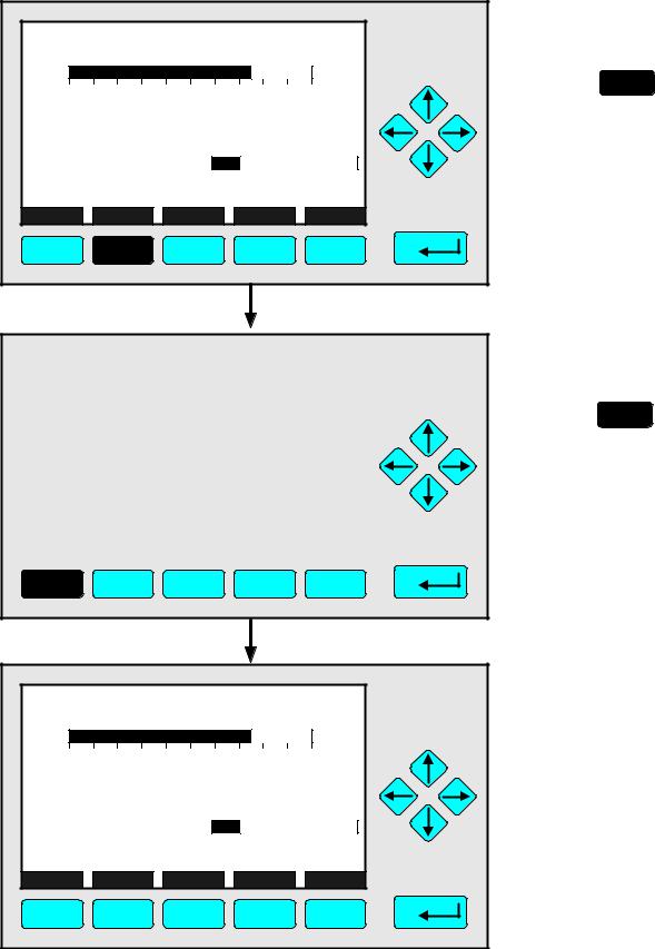
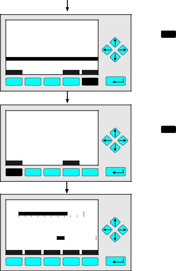
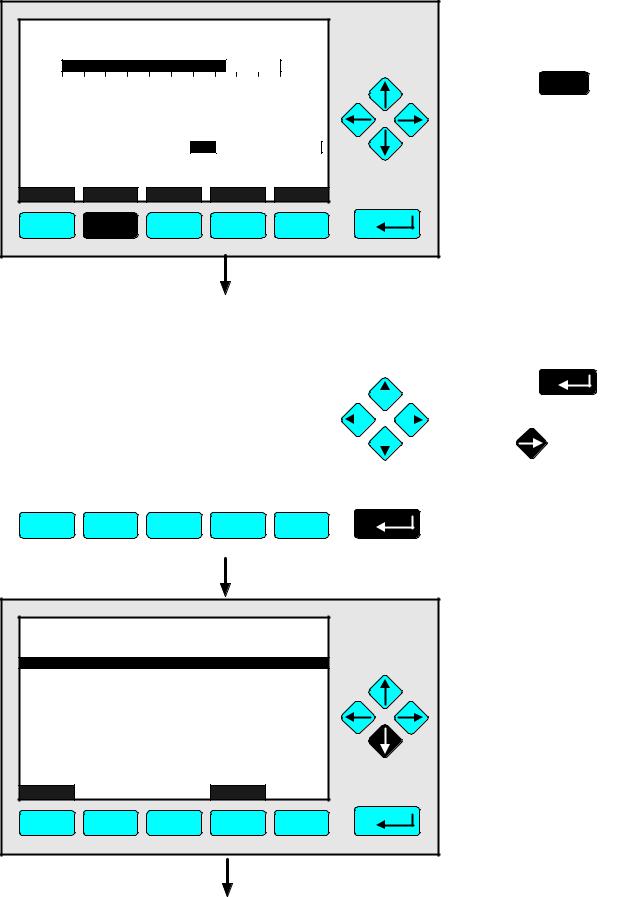
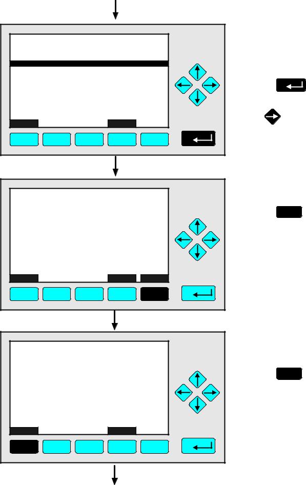
No |
Alarms: |
|
|
|
|
|
|
|
No |
Failures: |
|
|
|
|
|
|
|
No |
Maintenance requests: |
|
|
|
No |
||||
Function control/Service: |
|
|
|
No |
||||
|
|
|
|
|
|
|
|
|
Measure |
|
RawMeas |
|
|
Channel |
|
Back... |
|
F1 |
F2 |
|
F3 |
|
F4 |
F5 |
TAG |
|
|
|
|
|
|
37.50 |
|
|
|
ppm CH4 |
||
0.00 |
|
|
Range: 1 |
50.00 |
||
Failures: |
|
|
No |
|
|
|
Maintenance-Requests: |
No |
|
|
|
||
Temperature: |
|
20.0 C |
0.0 |
|
100.0 |
|
Operation: |
|
Ready |
|
|
|
|
Display |
Status... |
|
Main... |
|
Channel |
Calib... |
F1 |
F2 |
|
F3 |
|
F4 |
F5 |
90003482(2) [NGA-e (MLT-Software 3.2.X)] 07/98 |
|
|
NGA 2000 |
|||
ÞChange to the menu "Analyzer Channel Status"
F2
Press
In the menu "Analyzer Channel Status" you can find status informations of the current channel.
Via the menu lines "Status details..." and "Operational settings..." you can change to further submenus.
(see 4.1.1 p. 4-5...30 and
4.1.2p. 4-31/32)
ÞChange to the single component display
F1
Press
Note:
Via the F2 key you can change to submenus containing the primary and secondary raw measurements.
ÞBack in the single component display
4 - 3
4 - 4 |
NGA 2000 |
90003482(2) [NGA-e (MLT-Software 3.2.X)] 07/98

4.1.1 Analyzer Channel Status - Status Details
Failures
TAG |
|
|
|
|
|
|
37.50 |
|
|
|
ppm CH4 |
||
0.00 |
|
|
Range: 1 |
50.00 |
||
Failures: |
|
|
No |
|
|
|
Maintenance-Requests: |
No |
|
|
|
||
Temperature: |
|
20.0 C |
0.0 |
|
100.0 |
|
Operation: |
|
Ready |
|
|
|
|
Display |
Status... |
|
Main... |
|
Channel |
Calib... |
F1 |
F2 |
|
F3 |
|
F4 |
F5 |
|
|
|
|
|
|
|
|
|
|
|
|
|
|
|
|
|
|
|
|
|
|
TAG |
|
|
|
|
|
|
|
|
|
37.50 ppm |
|
|
|
|
|
|
|||
|
|
|
|
-- Analyzer Channel Status -- |
|
|
|
|
|
|
|
|
|
|||||||
|
|
|
|
|
|
|
|
|
|
|
|
|
|
|
|
|
|
|||
|
Status details... |
|
|
|
|
|
|
|
|
|
|
|
|
|
|
|||||
|
Operational settings... |
|
|
|
|
|
|
|
|
|
|
|
|
|
|
|||||
|
|
|
|
|
|
|
|
|
|
|
|
|
|
|
|
|
|
|
|
|
|
|
|
|
|
|
|
|
|
|
|
|
|
|
|
|
|||||
|
Hours of operations: |
|
|
|
|
|
164 |
|
|
|
|
|
|
|||||||
|
Operation status: |
|
|
|
|
|
|
Ready |
|
|
|
|
|
|
||||||
|
Events: |
|
|
|
|
|
|
|
|
|
|
|
No |
|
|
|
|
|
|
|
|
Alarms: |
|
|
|
|
|
|
|
|
|
|
|
No |
|
|
|
|
|
|
|
|
Failures: |
|
|
|
|
|
|
|
|
|
|
|
No |
|
|
|
|
|
|
|
|
Maintenance requests: |
|
|
|
|
|
|
|
No |
|
|
|
|
|
|
|||||
|
Function control/Service: |
|
|
|
|
|
|
|
No |
|
|
|
|
|
|
|||||
|
|
|
|
|
|
|
|
|
|
|
|
|
|
|
|
|
|
|
|
|
|
Measure |
|
RawMeas |
|
Channel |
|
Back... |
|
|
|
|
|
|
|
|
|
||||
|
|
|
|
|
|
|
|
|
|
|
|
|
|
|
|
|||||
|
F1 |
F2 |
F3 |
|
F4 |
F5 |
||||||||||||||
|
|
|
|
|
|
|
|
|
|
|
|
|
|
|
|
|
|
|
|
|
TAG |
37.50 ppm |
-- Status Details --
Failures...
Maintenance requests...
Function controls...
Measurements/Alarms...
Events...
Acknowledge and clear failures !
Acknowledge and clear maintenance requests !
Acknowledge and clear function controls !
Measure |
|
|
Back... |
|
F1 |
F2 |
F3 |
F4 |
F5 |
ÞChange to the menu "Analyzer Channel Status"
F2
Press
ÞChange to the submenu "Status Details"
Press
or
ÞChange to the "List of Possible Failures (page 1 of 2)"
Press
or
90003482(2) [NGA-e (MLT-Software 3.2.X)] 07/98
NGA 2000 |
4 - 5 |
|
|
|
|
|
Þ Change to the |
MLT25/CH2/R2 |
|
|
37.50 ppm |
second menu page |
|
|
-- List of Possible Failures(1/2) -- |
|
|
||
One or more failures: |
|
|
No |
F5 |
|
Configuration replaced by factory setting: |
No |
Press |
|||
Chopper fail: |
|
|
No |
|
|
Raw signal too high: |
|
|
No |
|
|
Detector signal communication failed: |
No |
|
|||
Raw signal too low: |
|
|
No |
|
|
(reserved) |
|
|
|
|
|
(reserved) |
|
|
|
|
|
Temperature measurement: |
|
No |
|
||
Invalid pressure measurement: |
|
No |
|
||
Measure |
|
|
Back... |
More... |
|
F1 |
F2 |
F3 |
F4 |
F5 |
|
|
|
|
Þ Change to the |
MLT25/CH2/R2 |
|
37.50 ppm |
single component |
-- List of Possible Failures(2/2) -- |
|
display |
|
External Input: |
|
No |
F1 |
Linearization underflow: |
|
No |
|
Linearization overflow: |
|
No |
Press |
Measure |
Back... |
|
|
F1 |
F2 |
|
F3 |
|
F4 |
F5 |
|
|
|
|
|
|
|
|
Þ Back in the single |
TAG |
|
|
|
|
|
|
component display |
37.50 |
|
|
|
ppm CH4 |
of the current |
||
|
|
|
channel |
||||
|
|
|
|
|
|
|
|
0.00 |
|
|
Range: 1 |
50.00 |
|
||
Failures: |
|
|
No |
|
|
|
|
Maintenance-Requests: |
No |
|
|
|
|
||
Temperature: |
|
20.0 C |
0.0 |
|
100.0 |
|
|
Operation: |
|
Ready |
|
|
|
|
|
Display |
Status... |
|
Main... |
|
Channel |
Calib... |
|
F1 |
F2 |
|
F3 |
|
F4 |
F5 |
|
4 - 6 |
|
|
|
|
|
NGA 2000 |
90003482(2) [NGA-e (MLT-Software 3.2.X)] 07/98 |
4.1.1 Analyzer Channel Status - Status Details
Maintenance Requests
TAG |
|
|
|
|
|
|
37.50 |
|
|
|
ppm CH4 |
||
0.00 |
|
|
Range: 1 |
50.00 |
||
Failures: |
|
|
No |
|
|
|
Maintenance-Requests: |
No |
|
|
|
||
Temperature: |
|
20.0 C |
0.0 |
|
100.0 |
|
Operation: |
|
Ready |
|
|
|
|
Display |
Status... |
|
Main... |
|
Channel |
Calib... |
F1 |
F2 |
|
F3 |
|
F4 |
F5 |
|
|
|
|
|
|
|
|
|
|
|
|
|
|
|
|
|
|
|
|
|
|
TAG |
|
|
|
|
|
|
|
|
|
37.50 ppm |
|
|
|
|
|
|
|||
|
|
|
|
-- Analyzer Channel Status -- |
|
|
|
|
|
|
|
|
|
|||||||
|
|
|
|
|
|
|
|
|
|
|
|
|
|
|
|
|
|
|||
|
Status details... |
|
|
|
|
|
|
|
|
|
|
|
|
|
|
|||||
|
Operational settings... |
|
|
|
|
|
|
|
|
|
|
|
|
|
|
|||||
|
|
|
|
|
|
|
|
|
|
|
|
|
|
|
|
|
|
|
|
|
|
|
|
|
|
|
|
|
|
|
|
|
|
|
|
|
|||||
|
Hours of operations: |
|
|
|
|
|
164 |
|
|
|
|
|
|
|||||||
|
Operation status: |
|
|
|
|
|
|
Ready |
|
|
|
|
|
|
||||||
|
Events: |
|
|
|
|
|
|
|
|
|
|
|
No |
|
|
|
|
|
|
|
|
Alarms: |
|
|
|
|
|
|
|
|
|
|
|
No |
|
|
|
|
|
|
|
|
Failures: |
|
|
|
|
|
|
|
|
|
|
|
No |
|
|
|
|
|
|
|
|
Maintenance requests: |
|
|
|
|
|
|
|
No |
|
|
|
|
|
|
|||||
|
Function control/Service: |
|
|
|
|
|
|
|
No |
|
|
|
|
|
|
|||||
|
|
|
|
|
|
|
|
|
|
|
|
|
|
|
|
|
|
|
|
|
|
Measure |
|
RawMeas |
|
Channel |
|
Back... |
|
|
|
|
|
|
|
|
|
||||
|
|
|
|
|
|
|
|
|
|
|
|
|
|
|
|
|||||
|
F1 |
F2 |
F3 |
|
F4 |
F5 |
||||||||||||||
|
|
|
|
|
|
|
|
|
|
|
|
|
|
|
|
|
|
|
|
|
TAG |
37.50 ppm |
-- Status Details --
Failures...
Maintenance requests...
Function controls...
Measurements/Alarms...
Events...
Acknowledge and clear failures !
Acknowledge and clear maintenance requests !
Acknowledge and clear function controls !
Measure |
|
|
Back... |
|
F1 |
F2 |
F3 |
F4 |
F5 |
ÞChange to the menu "Analyzer Channel Status"
F2
Press
ÞChange to the submenu "Status Details"
Press
or
ÞChange to the line "Maintenance requests..."
Press  or
or  as often as necessary to get the menu line "Maintenance requests..." white on black.
90003482(2) [NGA-e (MLT-Software 3.2.X)] 07/98
NGA 2000 |
4 - 7 |
|
|
|
|
|
Þ Change to the |
TAG |
|
|
|
37.50 ppm |
"List of Possible |
|
-- Status Details -- |
|
Maintenance |
||
Failures... |
|
|
|
|
Requests |
Maintenance requests... |
|
|
|
(page 1 of 2)" |
|
Function controls... |
|
|
|
|
|
Measurements/Alarms... |
|
|
|
|
|
Events... |
|
|
|
|
|
Acknowledge and clear failures ! |
|
|
Press |
||
|
|
|
|||
Acknowledge and clear maintenance requests ! |
|
|
|||
Acknowledge and clear function controls ! |
|
|
|||
Measure |
|
|
Back... |
|
or |
F1 |
F2 |
F3 |
F4 |
F5 |
|
|
|
|
Þ Change to the |
MLT25/CH2/R2 |
|
37.50 ppm |
second menu page |
-- List of Possible Maintenance Requests(1/2) -- |
|
||
One or more maintenance requests: |
|
No |
F5 |
|
Press |
||
Too much hours of operation: |
|
No |
|
Zero calibration - deviation too high: |
|
No |
|
Span calibration - deviation too high: |
|
No |
|
Measurement too noisy for zero calibration: |
No |
|
|
Measurement too noisy for span calibration: |
No |
|
|
Measure |
Back... |
More... |
|
F1 |
F2 |
F3 |
F4 |
F5 |
|
|
|
|
|
|
Þ Change to the |
MLT25/CH2/R2 |
|
|
37.50 ppm |
single component |
|
|
-- List of Possible Maintenance Requests(2/2) -- |
display |
|||
External Input: |
|
|
No |
F1 |
|
|
|
|
|
|
|
|
|
|
|
|
Press |
Measure |
|
Back... |
|
|
|
F1 |
F2 |
F3 |
F4 |
F5 |
|
4 - 8 |
|
|
|
NGA 2000 |
90003482(2) [NGA-e (MLT-Software 3.2.X)] 07/98 |
4.1.1 Analyzer Channel Status - Status Details
Maintenance Requests
|
|
|
|
|
|
|
Þ Back in the single |
TAG |
|
|
|
|
|
|
component display |
37.50 |
|
|
|
ppm CH4 |
of the current |
||
|
|
|
channel |
||||
|
|
|
|
|
|
|
|
0.00 |
|
|
Range: 1 |
50.00 |
|
||
Failures: |
|
|
No |
|
|
|
|
Maintenance-Requests: |
No |
|
|
|
|
||
Temperature: |
|
20.0 C |
0.0 |
|
100.0 |
|
|
Operation: |
|
Ready |
|
|
|
|
|
Display |
Status... |
|
Main... |
|
Channel |
Calib... |
|
F1 |
F2 |
|
F3 |
|
F4 |
F5 |
|
90003482(2) [NGA-e (MLT-Software 3.2.X)] 07/98
NGA 2000 |
4 - 9 |
4 - 10 |
NGA 2000 |
90003482(2) [NGA-e (MLT-Software 3.2.X)] 07/98
Loading...