


 Loading...


 Precision Cooling


 For Business-Critical Continuity™


 Liebert® XDR™


 User Manual

IMPORTANT SAFETY GUIDELINES
SAVE THESE INSTRUCTIONS
! WARNING
Risk of top-heavy module falling over. Can cause equipment damage, personal injury or death.
Improper handling can cause equipment damage, injury, or death. Read all of the following instructions before attempting to move, lift, remove packaging from the module, or preparing module for installation.
! WARNING
Risk of explosive discharge of high-pressure refrigerant. Can cause personal injury or death.
This module contains fluids and/or gases under high pressure. Relieve system pressure before cutting into or disconnecting piping or piping components.
! WARNING
Risk of piping and component rupture. May cause equipment damage, personal injury or death.
Closing service valves may isolate liquid refrigerant, causing high pressure and rupture of piping. Do not close valves without following recommended procedures for repair, maintenance and replacement of components. Install pressure relief valves in field piping that may become isolated by service valves.
! CAUTION
Risk of sharp edges, splinters and exposed fasteners. Can cause personal injury.
Only properly trained personnel wearing appropriate safety headgear, gloves, shoes and glasses should attempt to move, lift, remove packaging from, or prepare module for installation.
! CAUTION
Risk of improper operation and overpressurization. Can cause in personal injury or property damage.
Only personnel properly trained and qualified in HVAC installation or service should install or service this equipment.
Read all installation, operating and safety instructions before proceeding.
NOTICE
Risk of overhead interference. Can cause module or structural damage.
The module may be too tall to fit through a doorway while on the skid. Measure the module and doorway heights and verify clearances by referring to the installation plans and other site-specific drawings and documents before moving the module.
Fluorinated Greenhouse Gas Requirements—European Union
Stationary air conditioning, refrigeration, heat pump equipments and stationary fire protection systems in the European Community market and operating with fluorinated greenhouse gases (f-gas), such as R407C, R134a, R410A, must comply with the F-Gas Regulation: (EC) No. 842/2006 (F-gas). The regulation prohibits, among other actions, venting fluorinated greenhouse gases to the atmosphere.
The F-Gas Regulation also requires operators to use all measures that are technically feasible and do not entail disproportionate cost to prevent leakage of these gases, to test for leakage regularly and to recover f-gas during equipment service and maintenance and before disposing of equipment.
Refer to the full regulation for additional details.

TABLE OF CONTENTS
IMPORTANT SAFETY GUIDELINES . . . . . . . . . . . . . . . . . . . . . . . . . . . . . . . . . . INSIDE FRONT COVER
1.0 COMPONENT LOCATIONS AND MODEL NUMBER NOMENCLATURE. . . . . . . . . . . . . . . . . . . . .1
2.0 INTRODUCTION . . . . . . . . . . . . . . . . . . . . . . . . . . . . . . . . . . . . . . . . . . . . . . . . . . . . . . . . . .2
2.1 References . . . . . . . . . . . . . . . . . . . . . . . . . . . . . . . . . . . . . . . . . . . . . . . . . . . . . . . . . . . . . . . . . . 2
2.2 Pre-Installation Checks . . . . . . . . . . . . . . . . . . . . . . . . . . . . . . . . . . . . . . . . . . . . . . . . . . . . . . . 2
2.3 Packing List . . . . . . . . . . . . . . . . . . . . . . . . . . . . . . . . . . . . . . . . . . . . . . . . . . . . . . . . . . . . . . . . 2
2.4 Installation Considerations . . . . . . . . . . . . . . . . . . . . . . . . . . . . . . . . . . . . . . . . . . . . . . . . . . . . 2
2.4.1 Room Preparation. . . . . . . . . . . . . . . . . . . . . . . . . . . . . . . . . . . . . . . . . . . . . . . . . . . . . . . . . . . . . 2
3.0 GENERAL PRODUCT INFORMATION . . . . . . . . . . . . . . . . . . . . . . . . . . . . . . . . . . . . . . . . . . .3
3.1 Product/System Description. . . . . . . . . . . . . . . . . . . . . . . . . . . . . . . . . . . . . . . . . . . . . . . . . . . . 3 3.2 Checking and Unpacking . . . . . . . . . . . . . . . . . . . . . . . . . . . . . . . . . . . . . . . . . . . . . . . . . . . . . . 3
3.2.1 Recyclable Packaging . . . . . . . . . . . . . . . . . . . . . . . . . . . . . . . . . . . . . . . . . . . . . . . . . . . . . . . . . . 4 3.2.2 Module Handling . . . . . . . . . . . . . . . . . . . . . . . . . . . . . . . . . . . . . . . . . . . . . . . . . . . . . . . . . . . . . 4 3.2.3 Unpacking the Module . . . . . . . . . . . . . . . . . . . . . . . . . . . . . . . . . . . . . . . . . . . . . . . . . . . . . . . . . 5 3.2.4 Removing the Liebert XDR from the Pallet . . . . . . . . . . . . . . . . . . . . . . . . . . . . . . . . . . . . . . . . 7
4.0 MECHANICAL CONSIDERATIONS . . . . . . . . . . . . . . . . . . . . . . . . . . . . . . . . . . . . . . . . . . . . .8
4.1 Liebert XDR Dimensions . . . . . . . . . . . . . . . . . . . . . . . . . . . . . . . . . . . . . . . . . . . . . . . . . . . . . . 8
4.2 Determining Placement in the Conditioned Space. . . . . . . . . . . . . . . . . . . . . . . . . . . . . . . . . 10
4.3 Airflow. . . . . . . . . . . . . . . . . . . . . . . . . . . . . . . . . . . . . . . . . . . . . . . . . . . . . . . . . . . . . . . . . . . . 11
5.0 INSTALLATION . . . . . . . . . . . . . . . . . . . . . . . . . . . . . . . . . . . . . . . . . . . . . . . . . . . . . . . . .12
5.1 Installing the Rack-Mounting Kit onto the Rack . . . . . . . . . . . . . . . . . . . . . . . . . . . . . . . . . . 12 5.2 Mounting the Liebert XDR on the Rack-Mounting Kit . . . . . . . . . . . . . . . . . . . . . . . . . . . . . 12 5.3 Door Safety Catch. . . . . . . . . . . . . . . . . . . . . . . . . . . . . . . . . . . . . . . . . . . . . . . . . . . . . . . . . . . 13
6.0 PIPING . . . . . . . . . . . . . . . . . . . . . . . . . . . . . . . . . . . . . . . . . . . . . . . . . . . . . . . . . . . . . . .14
6.1 European Union Fluorinated Greenhouse Gas Requirements . . . . . . . . . . . . . . . . . . . . . . . 14
6.2 System Connection Configuration. . . . . . . . . . . . . . . . . . . . . . . . . . . . . . . . . . . . . . . . . . . . . . 14
6.3 Connection Methods and Points . . . . . . . . . . . . . . . . . . . . . . . . . . . . . . . . . . . . . . . . . . . . . . . 15
6.4 Insulation . . . . . . . . . . . . . . . . . . . . . . . . . . . . . . . . . . . . . . . . . . . . . . . . . . . . . . . . . . . . . . . . . 15
6.5Venting the Holding Charge for Hard-Piped or Removable Liebert XD Flex Pipe
Couplings . . . . . . . . . . . . . . . . . . . . . . . . . . . . . . . . . . . . . . . . . . . . . . . . . . . . . . . . . . . . . . . . . 15
6.5.1 Brazing Preparations . . . . . . . . . . . . . . . . . . . . . . . . . . . . . . . . . . . . . . . . . . . . . . . . . . . . . . . . . 16
6.5.2 Recommended Piping Size . . . . . . . . . . . . . . . . . . . . . . . . . . . . . . . . . . . . . . . . . . . . . . . . . . . . . 16
6.6 Hard-Piped Connection Sizes . . . . . . . . . . . . . . . . . . . . . . . . . . . . . . . . . . . . . . . . . . . . . . . . . 16
6.6.1 Leak-Checking and Evacuation. . . . . . . . . . . . . . . . . . . . . . . . . . . . . . . . . . . . . . . . . . . . . . . . . 17
6.6.2 Header System . . . . . . . . . . . . . . . . . . . . . . . . . . . . . . . . . . . . . . . . . . . . . . . . . . . . . . . . . . . . . . 17
i

6.7 Field Installation of Liebert XD Flex Pipe Kit on Liebert XDR . . . . . . . . . . . . . . . . . . . . . . 18
6.7.1 Connecting Methods—One-Shot Couplings for Pre-Charged Refrigerant Option . . . . . . . . . 19 6.7.2 Connect a Liebert XDR with One-Shot Couplings to Liebert XD Flex Pipe . . . . . . . . . . . . . . 20 6.7.3 Connection Methods—Removable Couplings . . . . . . . . . . . . . . . . . . . . . . . . . . . . . . . . . . . . . . 22
6.7.4Connect Liebert XD Flex Pipe with Removable Coupling to a Liebert XD Cooling
Module. . . . . . . . . . . . . . . . . . . . . . . . . . . . . . . . . . . . . . . . . . . . . . . . . . . . . . . . . . . . . . . . . . . . . 22 6.7.5 Connect a Liebert XDR with Liebert XD Flex Pipe to a Liebert XD System . . . . . . . . . . . . . 23 6.7.6 Disconnect a Liebert XD Flex Pipe from a Liebert XD System . . . . . . . . . . . . . . . . . . . . . . . . 27 6.7.7 Disconnecting the Liebert XD Flex Pipe from the Liebert XDR . . . . . . . . . . . . . . . . . . . . . . . 28 6.7.8 Removing the Liebert XDR from a Cabinet . . . . . . . . . . . . . . . . . . . . . . . . . . . . . . . . . . . . . . . 28
7.0 INSTALLATION CHECKLIST AND SYSTEM FILL FOR STARTUP . . . . . . . . . . . . . . . . . . . . . . .29
7.1 Checklist for Proper Installation . . . . . . . . . . . . . . . . . . . . . . . . . . . . . . . . . . . . . . . . . . . . . . . 29 7.2 Charging with Refrigerant. . . . . . . . . . . . . . . . . . . . . . . . . . . . . . . . . . . . . . . . . . . . . . . . . . . . 29
8.0 STARTING THE LIEBERT XD SYSTEM. . . . . . . . . . . . . . . . . . . . . . . . . . . . . . . . . . . . . . . . .30
9.0 MAINTENANCE . . . . . . . . . . . . . . . . . . . . . . . . . . . . . . . . . . . . . . . . . . . . . . . . . . . . . . . . .31
9.1 Fluorinated Greenhouse Gas Requirements. . . . . . . . . . . . . . . . . . . . . . . . . . . . . . . . . . . . . . 31
10.0 SPECIFICATIONS . . . . . . . . . . . . . . . . . . . . . . . . . . . . . . . . . . . . . . . . . . . . . . . . . . . . . . . .32
ii

FIGURES
Figure 1 Liebert XDR component locations . . . . . . . . . . . . . . . . . . . . . . . . . . . . . . . . . . . . . . . . . . . . . . . . . . . 1 Figure 2 Liebert XDR model number nomenclature . . . . . . . . . . . . . . . . . . . . . . . . . . . . . . . . . . . . . . . . . . . . 1 Figure 3 Generic piping layout . . . . . . . . . . . . . . . . . . . . . . . . . . . . . . . . . . . . . . . . . . . . . . . . . . . . . . . . . . . . . 3 Figure 4 Recommended module handling equipment . . . . . . . . . . . . . . . . . . . . . . . . . . . . . . . . . . . . . . . . . . . 4 Figure 5 Removing packaging . . . . . . . . . . . . . . . . . . . . . . . . . . . . . . . . . . . . . . . . . . . . . . . . . . . . . . . . . . . . . . 6 Figure 6 Remove Liebert XDR from pallet . . . . . . . . . . . . . . . . . . . . . . . . . . . . . . . . . . . . . . . . . . . . . . . . . . . . 7 Figure 7 Overall dimensions with hard-piped connections . . . . . . . . . . . . . . . . . . . . . . . . . . . . . . . . . . . . . . . 8 Figure 8 Overall dimensions with one-shot coupling (pre-charged) . . . . . . . . . . . . . . . . . . . . . . . . . . . . . . . . 9 Figure 9 Overall dimensions with removable coupling . . . . . . . . . . . . . . . . . . . . . . . . . . . . . . . . . . . . . . . . . 10 Figure 10 Generic airflow diagram . . . . . . . . . . . . . . . . . . . . . . . . . . . . . . . . . . . . . . . . . . . . . . . . . . . . . . . . . . 11 Figure 11 Liebert XDR mounting locations . . . . . . . . . . . . . . . . . . . . . . . . . . . . . . . . . . . . . . . . . . . . . . . . . . . 12 Figure 12 Typical Liebert XDR piping—interlaced connections . . . . . . . . . . . . . . . . . . . . . . . . . . . . . . . . . . . 14 Figure 13 Typical Liebert XDR piping—non-interlaced connection . . . . . . . . . . . . . . . . . . . . . . . . . . . . . . . . 15 Figure 14 Piping location and connection sizes—modules with hard-piped connections . . . . . . . . . . . . . . . 16 Figure 15 Hard pipe connection diagram . . . . . . . . . . . . . . . . . . . . . . . . . . . . . . . . . . . . . . . . . . . . . . . . . . . . . 17 Figure 16 Liebert XD Flex Pipe dimensions—straight and 90-degree connections. . . . . . . . . . . . . . . . . . . . 18 Figure 17 Piping location and connection sizes—modules with pre-charged modules . . . . . . . . . . . . . . . . . 19 Figure 18 Male coupling on Liebert XD cooling module . . . . . . . . . . . . . . . . . . . . . . . . . . . . . . . . . . . . . . . . . 20 Figure 19 Female one-shot coupling Liebert Flex Pipe: Schrader valve location . . . . . . . . . . . . . . . . . . . . . 20 Figure 20 Hex body, union nut on one-shot coupling. . . . . . . . . . . . . . . . . . . . . . . . . . . . . . . . . . . . . . . . . . . . 21 Figure 21 Piping location and connection sizes—modules with removable couplings. . . . . . . . . . . . . . . . . . 22 Figure 22 Removable couplings. . . . . . . . . . . . . . . . . . . . . . . . . . . . . . . . . . . . . . . . . . . . . . . . . . . . . . . . . . . . . 23 Figure 23 Coupling size indicator . . . . . . . . . . . . . . . . . . . . . . . . . . . . . . . . . . . . . . . . . . . . . . . . . . . . . . . . . . . 24 Figure 24 Liebert XD prefabricated piping assembly . . . . . . . . . . . . . . . . . . . . . . . . . . . . . . . . . . . . . . . . . . . 24 Figure 25 Oil rings on header and Liebert XD Flex Pipe connectors . . . . . . . . . . . . . . . . . . . . . . . . . . . . . . . 25 Figure 26 Wrench arrangement for tightening couplings . . . . . . . . . . . . . . . . . . . . . . . . . . . . . . . . . . . . . . . . 25 Figure 27 Detail view of Liebert XD Flex Pipe and prefabricated piping port. . . . . . . . . . . . . . . . . . . . . . . . 26 Figure 28 Liebert XD prefabricated piping assembly and Liebert XD Flex Pipe. . . . . . . . . . . . . . . . . . . . . . 26 Figure 29 Piping mains without Liebert XD Flex Pipe . . . . . . . . . . . . . . . . . . . . . . . . . . . . . . . . . . . . . . . . . . 27
TABLES
Table 1 Branch piping sizes for pumped refrigerant loop . . . . . . . . . . . . . . . . . . . . . . . . . . . . . . . . . . . . . . 16
Table 2 Torque and wrench size for connecting Liebert XDR with one-shot couplings to
Liebert XD Flex Pipe. . . . . . . . . . . . . . . . . . . . . . . . . . . . . . . . . . . . . . . . . . . . . . . . . . . . . . . . . . . . . 21
Table 3 Torque and wrench sizes for connecting Liebert Flex Pipe to the Liebert XDR with
removable couplings . . . . . . . . . . . . . . . . . . . . . . . . . . . . . . . . . . . . . . . . . . . . . . . . . . . . . . . . . . . . . 22 Table 4 O-ring part number. . . . . . . . . . . . . . . . . . . . . . . . . . . . . . . . . . . . . . . . . . . . . . . . . . . . . . . . . . . . . . 23 Table 5 Torque for connecting Liebert XD Flex Pipe to prefabricated piping . . . . . . . . . . . . . . . . . . . . . . 25 Table 6 Liebert XDR specifications . . . . . . . . . . . . . . . . . . . . . . . . . . . . . . . . . . . . . . . . . . . . . . . . . . . . . . . . 32 Table 7 Rack mounting kit. . . . . . . . . . . . . . . . . . . . . . . . . . . . . . . . . . . . . . . . . . . . . . . . . . . . . . . . . . . . . . . 32 Table 8 Liebert XD Flex Pipe one-shot assemblies, supply and return . . . . . . . . . . . . . . . . . . . . . . . . . . . 32 Table 9 Liebert XD Flex Pipe removable assemblies, supply and return . . . . . . . . . . . . . . . . . . . . . . . . . . 32
iii

iv
Component Locations and Model Number Nomenclature
1.0COMPONENT LOCATIONS AND MODEL NUMBER NOMENCLATURE
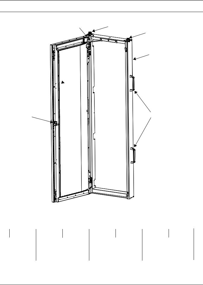
Figure 1 Liebert XDR component locations |
|
2 |
3 |
1
7
4 
5 |
6 |
|
|
|
|
|
|
1. |
Supply Line |
|
|
|
|
|
|
|
2. |
Door Safety Catch |
|
|
|
|
|
|
|
3. |
Return Line |
|
|
|
|
|
|
|
4. |
Evaporator Coils |
|
|
|
|
|
|
|
5. |
Locking Door Latch |
|
|
|
|
|
|
|
6. |
Removable Installation Handles |
||
|
|
|
|
|
7. |
Frame |
|
|
Figure 2 Liebert XDR model number nomenclature |
|
|
|
|
|
|||
|
|
|
Example: XDR20B1R — * |
|
|
|
||
XD |
R |
20 |
B |
1 |
R |
— |
* |
|
Liebert |
|
20 = Model Size |
1 = Standard |
- = Domestic Packaging |
||||
X-treme |
|
|
|
|
|
E = Export Packaging |
|
|
heat |
|
|
|
|
|
|
|
|
density |
|
|
|
|
|
|
|
|
system |
|
|
|
|
|
|
|
|
|
Rear Cooling Module |
B = Basic Module |
|
- = Hard-Piping |
|
Revision |
||
|
|
|
|
|
P = Pre-Charged One-Shot |
|
level |
|
|
|
|
|
|
Coupling |
|
|
|
|
|
|
|
|
R = Removable Coupling |
|
|
|
1
Introduction
2.0INTRODUCTION
2.1References
This document must be used together with site specific documentation and documentation for other parts of the system.
2.2Pre-Installation Checks
•Check the received materials to be sure all required assemblies and parts have been received. If you discover any external damage, report it to the shipping company and your local Emerson representative.
2.3Packing List
•User manual (this document)
•Liebert XDR module
2.4Installation Considerations
The Liebert XDR is designed for attachment to the rear of computer cabinets in the data center. See
4.0 - Mechanical Considerations for details.
2.4.1Room Preparation
The room should be well-insulated and must have a sealed vapor barrier. The vapor barrier in the ceiling and walls can be a polyethylene film. Paint on concrete walls and floors should contain either rubber or plastic.
NOTE
The vapor barrier is the single most important requirement for maintaining environmental
control in the conditioned space.
Outside or fresh air should be kept to a minimum when temperature and humidity must be tightly controlled. Outside air adds to the cooling, heating, dehumidifying and humidifying loads of the site. Doors should be properly sealed to minimize leaks and should not contain ventilation grilles.
2
General Product Information
3.0GENERAL PRODUCT INFORMATION
3.1Product/System Description
The Liebert XDR is a cooling system for high-density heat loads that mounts on the rear of a 24" x 42U rack (for other sizes consult the factory) and maintains access to the back of the server
rack. Room air is drawn in through the front of the rack and picks up heat from the servers. The coil captures that heat, cooling the air, which is expelled through the rear of the rack.
The Liebert XDR relies on the rack equipment’s fans to move air across the micro-channel coil. Captured heat is carried away through pumped R-134a refrigerant supplied by either a Liebert XDP™ or Liebert XDC™.
The complete cooling system may include other Liebert XD cooling modules, such as the Liebert XDO™, Liebert XDV™, Liebert XDH™, Liebert XDA™ or Liebert XDCF™ (see Figure 3) and Liebert XD Flex Piping.
The Liebert XDR is not expected to produce any condensation because of its location, usually in the data center. A condensate pan is provided as a precaution. It does not have a drain fitting or other means of being emptied.
Four handles to ease carrying the Liebert XDR are attached at the factory. These should be removed after the module is attached to the rear of the enclosure. Leaving the handles attached would require space between the racks. The handles should be retained for use if the Liebert XDR is removed from the enclosure.
Figure 3 Generic piping layout
|
|
|
|
|
|
|
|
|
|
|
|
|
|
|
|
|
|
|
LiebertXDC |
|
|
|
|
|
|
|
|
|
Liebert |
|
|
|
|
|
|
or |
|
|
|
|
|
|
|
|
|
|
Supply Lines |
|||
|
|
|
|
|
|
|
|
|
|
|
XD Cooling Module* |
|
|
|
||
|
|
|
|
|
|
|
|
|
|
|
||||||
|
|
|
|
|
|
|
|
|
|
|
|
|
||||
|
|
|
|
|
|
|
|
|
|
|
|
|
||||
|
|
Liebert XDP |
|
Pumped |
|
|
|
|
|
|
|
|
|
|
|
|
|
|
|
|
|
|
|
|
|
|
|
|
|
|
|||
|
|
|
|
Refrigerant |
|
|
|
|
|
|
|
|
|
|
Return Lines |
|
|
|
|
|
|
|
|
|
|
|
|
|
|
|
|||
|
|
|
|
R134a |
|
|
|
|
|
|
|
|
|
|
||
|
|
|
|
|
|
|
|
|
|
Liebert |
|
|
|
|||
|
|
|
|
|
|
|
|
|
|
|
|
|
||||
|
|
|
|
|
|
|
|
|
|
|
|
|
|
|||
|
|
|
|
|
|
|
|
|
|
|
|
XD Cooling Module* |
|
|
||
|
|
|
|
|
|
|
|
|
|
|
|
|
||||
|
|
|
|
|
|
|
|
|
|
|
|
|
|
|||
|
|
|
|
|
|
|
|
|
|
|
|
* Liebert XDCF ; Liebert XDH |
||||
|
|
|
|
|
|
|
|
|
|
|
|
Liebert XDO ; Liebert XDR |
||||
|
|
|
|
|
|
|
|
|
|
|
|
Liebert XDV |
|
|||
3.2Checking and Unpacking
Upon arrival of the module and before unpacking it, verify that the labeled equipment matches the bill of lading.
Inspect all items for either visible or concealed damage. Damage should be immediately reported to the carrier and a damage claim filed with a copy sent to Emerson or to your sales representative. If you later find any concealed damage, report it to both the shipping company and your local Emerson representative.
Check to be sure all required assemblies and parts have been received.
The Liebert XDR is shipped in protective packaging and secured to a pallet (see Figure 5). Do not remove these protective items from the Liebert XDR before it is at the installation location. When unpacking and handling the Liebert XDR, exercise extra care to prevent damage.
3
General Product Information
3.2.1 Recyclable Packaging
All material used to package this module is recyclable. Please save for future use R or dispose of the material appropriately.
! CAUTION
Risk of sharp edges, splinters and exposed fasteners. Can cause personal injury.
Only properly trained personnel wearing appropriate safety headgear, gloves, shoes and glasses should attempt to move, lift, remove packaging from, or prepare module for installation.
NOTICE
Risk of improper storage. Can cause module damage.
Keep the module indoors and protected from dampness, freezing temperatures and contact damage.
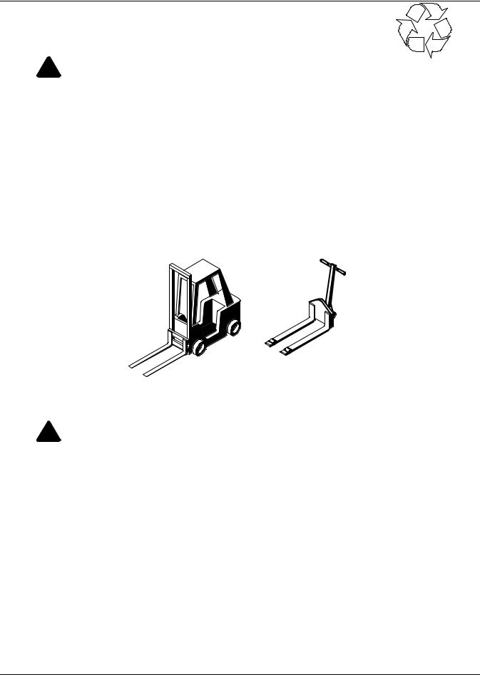
NOTICE
Risk of damage from forklift. Can cause exterior and/or underside damage. Keep tines of the forklift level and at a height suitable to fit below the skid.
Figure 4 Recommended module handling equipment
Pallet Jack
Forklift
3.2.2 Module Handling
! WARNING
Risk of 130-pound (59 kg) module falling. Can cause equipment damage, personal injury or death.
Do not leave a Liebert XDR standing unattended on its side or its end without adequate support to prevent it from falling over. The Liebert XDR must be supported at all times or laid flat on protective material until it is installed.
Two properly trained and qualified people are required to move the module.
When unpacking and handling the module, exercise extra care to prevent damage.
Use a forklift or pallet jack to move the Liebert XDR. If multiple Liebert XDR modules are delivered, they will be shipped on a pallet with up to four modules. A pallet jack will be required to move these modules to the installation location.
•If using a forklift or pallet jack, ensure that the fork tine length is suitable to safely move the packaged module.
•Keep the module in the protective packaging until it has been moved to the installation site.
•When handling and unpacking the module, exercise great care to prevent damage.
•Do not lift the module any higher than 6" (152mm) while moving it. If it must be lifted higher than 6" (152mm), exercise great care and keep all personnel who are not helping move the module at least 20 feet (5m) away from the module.
•Do not use module piping to lift or move the Liebert XDR.
4
General Product Information
3.2.3Unpacking the Module
! WARNING
Risk of 130-pound (59 kg) module falling. Can cause equipment damage, personal injury or death.
Do not leave a Liebert XDR standing unattended on its side or its end without adequate support to prevent it from falling over. The Liebert XDR must be supported at all times or laid flat on protective material until it is installed.
Two properly trained and qualified people are required to move the module.
Do not unpack the Liebert XDR before moving it to the installation location. Once at the installation point:
1.Cut the banding and place all packaged modules on the floor for unpacking.
2.Unbend all metal tabs as shown in Figure 5.
Use any of these tools to unbend the tabs: flat-blade screwdriver, claw hammer, pliers or crowbar.
3.Remove the top cover from the package.
4.Remove the center top brace.
5.Remove and set aside the hardware and key package.
6.Remove side panels from package.
7.Remove top protective foam from the package.
5

General Product Information
Figure 5 Removing packaging
Step 1
Cut
Bands
Step 2
Unbend Tabs
|
Hardware |
Step 3 |
|
and Keys |
|
|
|
|
Steps 4, and 5 |
|
Remove the |
Center Top Brace |
|
Top Cover |
|
|
Step 7
Remove Foam
Protecting Top
of Module
Step 6
Remove
Side
Panels
6
Loading...