


 Loading...


 AC Power


 For Business-Critical Continuity™


 Liebert NX™ UPS


 User Manual–40-120kVA, 480V, 60Hz

TABLE OF CONTENTS
IMPORTANT SAFETY INSTRUCTIONS . . . . . . . . . . . . . . . . . . . . . . . . . . . . . . . . . . . . . . . . . . . . . . . .1 GLOSSARY OF SYMBOLS . . . . . . . . . . . . . . . . . . . . . . . . . . . . . . . . . . . . . . . . . . . . . . . . . . . . . . . .3 1.0 INSTALLATION . . . . . . . . . . . . . . . . . . . . . . . . . . . . . . . . . . . . . . . . . . . . . . . . . . . . . . . . . .4
1.1 External Inspections . . . . . . . . . . . . . . . . . . . . . . . . . . . . . . . . . . . . . . . . . . . . . . . . . . . . . . . . . 4 1.2 Internal Inspections . . . . . . . . . . . . . . . . . . . . . . . . . . . . . . . . . . . . . . . . . . . . . . . . . . . . . . . . . . 5
1.2.1 Storing for Delayed Installation . . . . . . . . . . . . . . . . . . . . . . . . . . . . . . . . . . . . . . . . . . . . . . . . . 5
1.3 Preliminary Checks . . . . . . . . . . . . . . . . . . . . . . . . . . . . . . . . . . . . . . . . . . . . . . . . . . . . . . . . . . 5
1.3.1 Identification. . . . . . . . . . . . . . . . . . . . . . . . . . . . . . . . . . . . . . . . . . . . . . . . . . . . . . . . . . . . . . . . . 5
1.4 UPS Location . . . . . . . . . . . . . . . . . . . . . . . . . . . . . . . . . . . . . . . . . . . . . . . . . . . . . . . . . . . . . . . 5
1.4.1 Positioning the UPS . . . . . . . . . . . . . . . . . . . . . . . . . . . . . . . . . . . . . . . . . . . . . . . . . . . . . . . . . . . 5 1.4.2 Environmental Considerations . . . . . . . . . . . . . . . . . . . . . . . . . . . . . . . . . . . . . . . . . . . . . . . . . . 5 1.4.3 Special Considerations for Parallel Systems . . . . . . . . . . . . . . . . . . . . . . . . . . . . . . . . . . . . . . . 6
1.5 Considerations in Moving the Liebert NX . . . . . . . . . . . . . . . . . . . . . . . . . . . . . . . . . . . . . . . . 6 1.6 Mechanical Considerations . . . . . . . . . . . . . . . . . . . . . . . . . . . . . . . . . . . . . . . . . . . . . . . . . . . . 6
1.6.1 Clearances. . . . . . . . . . . . . . . . . . . . . . . . . . . . . . . . . . . . . . . . . . . . . . . . . . . . . . . . . . . . . . . . . . . 7 1.6.2 Floor Installation . . . . . . . . . . . . . . . . . . . . . . . . . . . . . . . . . . . . . . . . . . . . . . . . . . . . . . . . . . . . . 7 1.6.3 Cable Entry. . . . . . . . . . . . . . . . . . . . . . . . . . . . . . . . . . . . . . . . . . . . . . . . . . . . . . . . . . . . . . . . . . 7 1.6.4 Optional Cabinets. . . . . . . . . . . . . . . . . . . . . . . . . . . . . . . . . . . . . . . . . . . . . . . . . . . . . . . . . . . . . 7
2.0 ELECTRICAL CONNECTIONS . . . . . . . . . . . . . . . . . . . . . . . . . . . . . . . . . . . . . . . . . . . . . . .10
2.1 Power Cabling. . . . . . . . . . . . . . . . . . . . . . . . . . . . . . . . . . . . . . . . . . . . . . . . . . . . . . . . . . . . . . 10
2.1.1 Cable Rating . . . . . . . . . . . . . . . . . . . . . . . . . . . . . . . . . . . . . . . . . . . . . . . . . . . . . . . . . . . . . . . . 10 2.1.2 UPS Input Configuration . . . . . . . . . . . . . . . . . . . . . . . . . . . . . . . . . . . . . . . . . . . . . . . . . . . . . . 11 2.1.3 Cabling Guidelines . . . . . . . . . . . . . . . . . . . . . . . . . . . . . . . . . . . . . . . . . . . . . . . . . . . . . . . . . . . 11 2.1.4 Cable Connections . . . . . . . . . . . . . . . . . . . . . . . . . . . . . . . . . . . . . . . . . . . . . . . . . . . . . . . . . . . 12 2.1.5 Safety Ground. . . . . . . . . . . . . . . . . . . . . . . . . . . . . . . . . . . . . . . . . . . . . . . . . . . . . . . . . . . . . . . 13 2.1.6 Protective Devices. . . . . . . . . . . . . . . . . . . . . . . . . . . . . . . . . . . . . . . . . . . . . . . . . . . . . . . . . . . . 13 2.1.7 Cabling Procedure . . . . . . . . . . . . . . . . . . . . . . . . . . . . . . . . . . . . . . . . . . . . . . . . . . . . . . . . . . . 14
2.2 Control Cables . . . . . . . . . . . . . . . . . . . . . . . . . . . . . . . . . . . . . . . . . . . . . . . . . . . . . . . . . . . . . 15
2.2.1 Monitor Board Features. . . . . . . . . . . . . . . . . . . . . . . . . . . . . . . . . . . . . . . . . . . . . . . . . . . . . . . 15
2.3 Dry Contacts . . . . . . . . . . . . . . . . . . . . . . . . . . . . . . . . . . . . . . . . . . . . . . . . . . . . . . . . . . . . . . . 16
2.3.1 Input Dry Contacts. . . . . . . . . . . . . . . . . . . . . . . . . . . . . . . . . . . . . . . . . . . . . . . . . . . . . . . . . . . 17 2.3.2 Maintenance Bypass Cabinet Interface . . . . . . . . . . . . . . . . . . . . . . . . . . . . . . . . . . . . . . . . . . 17 2.3.3 BCB Control Interface . . . . . . . . . . . . . . . . . . . . . . . . . . . . . . . . . . . . . . . . . . . . . . . . . . . . . . . . 18 2.3.4 Output Dry Contacts . . . . . . . . . . . . . . . . . . . . . . . . . . . . . . . . . . . . . . . . . . . . . . . . . . . . . . . . . 19 2.3.5 EPO Input—Optional. . . . . . . . . . . . . . . . . . . . . . . . . . . . . . . . . . . . . . . . . . . . . . . . . . . . . . . . . 20
3.0 BATTERY INSTALLATION . . . . . . . . . . . . . . . . . . . . . . . . . . . . . . . . . . . . . . . . . . . . . . . . . .21
3.1 Introduction . . . . . . . . . . . . . . . . . . . . . . . . . . . . . . . . . . . . . . . . . . . . . . . . . . . . . . . . . . . . . . . 21 3.2 Safety . . . . . . . . . . . . . . . . . . . . . . . . . . . . . . . . . . . . . . . . . . . . . . . . . . . . . . . . . . . . . . . . . . . . 21 3.3 External Battery Cabinet Installation . . . . . . . . . . . . . . . . . . . . . . . . . . . . . . . . . . . . . . . . . . 22
3.3.1 Battery Cabinets. . . . . . . . . . . . . . . . . . . . . . . . . . . . . . . . . . . . . . . . . . . . . . . . . . . . . . . . . . . . . 22 3.3.2 Connecting the Batteries . . . . . . . . . . . . . . . . . . . . . . . . . . . . . . . . . . . . . . . . . . . . . . . . . . . . . . 23 3.3.3 Installation Considerations . . . . . . . . . . . . . . . . . . . . . . . . . . . . . . . . . . . . . . . . . . . . . . . . . . . . 23 3.3.4 Connecting the Battery Cabinet to the UPS. . . . . . . . . . . . . . . . . . . . . . . . . . . . . . . . . . . . . . . 24
i

3.4 Non-Standard Batteries. . . . . . . . . . . . . . . . . . . . . . . . . . . . . . . . . . . . . . . . . . . . . . . . . . . . . . 24
3.5 BCB Shunt Trip . . . . . . . . . . . . . . . . . . . . . . . . . . . . . . . . . . . . . . . . . . . . . . . . . . . . . . . . . . . . 24
3.6 Alber Monitoring System—Optional. . . . . . . . . . . . . . . . . . . . . . . . . . . . . . . . . . . . . . . . . . . . 25
4.0 OPTIONS . . . . . . . . . . . . . . . . . . . . . . . . . . . . . . . . . . . . . . . . . . . . . . . . . . . . . . . . . . . . .26
4.1 Load Bus Synchronization . . . . . . . . . . . . . . . . . . . . . . . . . . . . . . . . . . . . . . . . . . . . . . . . . . . . 26
4.1.1 Performance Requirements . . . . . . . . . . . . . . . . . . . . . . . . . . . . . . . . . . . . . . . . . . . . . . . . . . . . 26
4.1.2 LBS Cable and Settings . . . . . . . . . . . . . . . . . . . . . . . . . . . . . . . . . . . . . . . . . . . . . . . . . . . . . . . 26
4.2 Configuring Parallel System Operation . . . . . . . . . . . . . . . . . . . . . . . . . . . . . . . . . . . . . . . . . 27
4.2.1 General . . . . . . . . . . . . . . . . . . . . . . . . . . . . . . . . . . . . . . . . . . . . . . . . . . . . . . . . . . . . . . . . . . . . 27
4.2.2 Features of Parallel System. . . . . . . . . . . . . . . . . . . . . . . . . . . . . . . . . . . . . . . . . . . . . . . . . . . . 27
4.2.3 Operating Principles. . . . . . . . . . . . . . . . . . . . . . . . . . . . . . . . . . . . . . . . . . . . . . . . . . . . . . . . . . 28
4.2.4 Operation Modes Summary . . . . . . . . . . . . . . . . . . . . . . . . . . . . . . . . . . . . . . . . . . . . . . . . . . . . 28
4.3 Installing Parallel System . . . . . . . . . . . . . . . . . . . . . . . . . . . . . . . . . . . . . . . . . . . . . . . . . . . . 28
4.3.1 Conditions for Parallel System . . . . . . . . . . . . . . . . . . . . . . . . . . . . . . . . . . . . . . . . . . . . . . . . . 29
4.3.2 Cabinet Installation . . . . . . . . . . . . . . . . . . . . . . . . . . . . . . . . . . . . . . . . . . . . . . . . . . . . . . . . . . 29
4.3.3 Preliminary Checks . . . . . . . . . . . . . . . . . . . . . . . . . . . . . . . . . . . . . . . . . . . . . . . . . . . . . . . . . . 29
4.3.4 Power Cables. . . . . . . . . . . . . . . . . . . . . . . . . . . . . . . . . . . . . . . . . . . . . . . . . . . . . . . . . . . . . . . . 29
4.3.5 Parallel Control Cables . . . . . . . . . . . . . . . . . . . . . . . . . . . . . . . . . . . . . . . . . . . . . . . . . . . . . . . 29
4.3.6 Emergency Power Off (EPO) . . . . . . . . . . . . . . . . . . . . . . . . . . . . . . . . . . . . . . . . . . . . . . . . . . . 32
5.0 UPS SPECIFICATIONS. . . . . . . . . . . . . . . . . . . . . . . . . . . . . . . . . . . . . . . . . . . . . . . . . . . .33
5.1 Conformity and Standards. . . . . . . . . . . . . . . . . . . . . . . . . . . . . . . . . . . . . . . . . . . . . . . . . . . . 33
5.2 UPS Environmental . . . . . . . . . . . . . . . . . . . . . . . . . . . . . . . . . . . . . . . . . . . . . . . . . . . . . . . . . 33
5.3 UPS Mechanical Characteristics . . . . . . . . . . . . . . . . . . . . . . . . . . . . . . . . . . . . . . . . . . . . . . . 33
5.4 UPS Electrical Characteristics . . . . . . . . . . . . . . . . . . . . . . . . . . . . . . . . . . . . . . . . . . . . . . . . 34
5.4.1 Input Rectifier. . . . . . . . . . . . . . . . . . . . . . . . . . . . . . . . . . . . . . . . . . . . . . . . . . . . . . . . . . . . . . . 35
5.4.2 DC Intermediate Circuit . . . . . . . . . . . . . . . . . . . . . . . . . . . . . . . . . . . . . . . . . . . . . . . . . . . . . . 36
5.4.3 Inverter Output . . . . . . . . . . . . . . . . . . . . . . . . . . . . . . . . . . . . . . . . . . . . . . . . . . . . . . . . . . . . . 36
5.4.4 Bypass Input. . . . . . . . . . . . . . . . . . . . . . . . . . . . . . . . . . . . . . . . . . . . . . . . . . . . . . . . . . . . . . . . 36
6.0 INSTALLATION DRAWINGS. . . . . . . . . . . . . . . . . . . . . . . . . . . . . . . . . . . . . . . . . . . . . . . . .37
7.0 OPERATION . . . . . . . . . . . . . . . . . . . . . . . . . . . . . . . . . . . . . . . . . . . . . . . . . . . . . . . . . . .53
7.1 General Description . . . . . . . . . . . . . . . . . . . . . . . . . . . . . . . . . . . . . . . . . . . . . . . . . . . . . . . . . 53
7.1.1 Bypass Supplies . . . . . . . . . . . . . . . . . . . . . . . . . . . . . . . . . . . . . . . . . . . . . . . . . . . . . . . . . . . . . 54
7.1.2 Operating Modes. . . . . . . . . . . . . . . . . . . . . . . . . . . . . . . . . . . . . . . . . . . . . . . . . . . . . . . . . . . . . 54
8.0 OPERATOR CONTROL AND DISPLAY PANEL . . . . . . . . . . . . . . . . . . . . . . . . . . . . . . . . . . .56
8.1 Operator Control Panel . . . . . . . . . . . . . . . . . . . . . . . . . . . . . . . . . . . . . . . . . . . . . . . . . . . . . . 56
8.1.1 Display Panel Layout . . . . . . . . . . . . . . . . . . . . . . . . . . . . . . . . . . . . . . . . . . . . . . . . . . . . . . . . . 56
8.2 Mimic Display Indicators. . . . . . . . . . . . . . . . . . . . . . . . . . . . . . . . . . . . . . . . . . . . . . . . . . . . . 58
8.3 Control Buttons . . . . . . . . . . . . . . . . . . . . . . . . . . . . . . . . . . . . . . . . . . . . . . . . . . . . . . . . . . . . 59
8.4 Audible Buzzer . . . . . . . . . . . . . . . . . . . . . . . . . . . . . . . . . . . . . . . . . . . . . . . . . . . . . . . . . . . . . 60
8.5 LCD Overview . . . . . . . . . . . . . . . . . . . . . . . . . . . . . . . . . . . . . . . . . . . . . . . . . . . . . . . . . . . . . 60
8.6 Navigation Keys . . . . . . . . . . . . . . . . . . . . . . . . . . . . . . . . . . . . . . . . . . . . . . . . . . . . . . . . . . . . 61
8.7 UPS System Information . . . . . . . . . . . . . . . . . . . . . . . . . . . . . . . . . . . . . . . . . . . . . . . . . . . . . 61
8.8 LCD Menus and Data Items . . . . . . . . . . . . . . . . . . . . . . . . . . . . . . . . . . . . . . . . . . . . . . . . . . 62
8.9 Language Selection . . . . . . . . . . . . . . . . . . . . . . . . . . . . . . . . . . . . . . . . . . . . . . . . . . . . . . . . . 64
ii

8.10 Current Date and Time . . . . . . . . . . . . . . . . . . . . . . . . . . . . . . . . . . . . . . . . . . . . . . . . . . . . . . 65 8.11 UPS Status Messages. . . . . . . . . . . . . . . . . . . . . . . . . . . . . . . . . . . . . . . . . . . . . . . . . . . . . . . . 66 8.12 Types of LCD Screens . . . . . . . . . . . . . . . . . . . . . . . . . . . . . . . . . . . . . . . . . . . . . . . . . . . . . . . 67
8.12.1 Opening Display . . . . . . . . . . . . . . . . . . . . . . . . . . . . . . . . . . . . . . . . . . . . . . . . . . . . . . . . . . . . . 67 8.12.2 Default Screen . . . . . . . . . . . . . . . . . . . . . . . . . . . . . . . . . . . . . . . . . . . . . . . . . . . . . . . . . . . . . . 67 8.12.3 UPS Help Screen . . . . . . . . . . . . . . . . . . . . . . . . . . . . . . . . . . . . . . . . . . . . . . . . . . . . . . . . . . . . 68 8.12.4 Screen Saver Window. . . . . . . . . . . . . . . . . . . . . . . . . . . . . . . . . . . . . . . . . . . . . . . . . . . . . . . . . 68
8.13 Pop-Up Windows . . . . . . . . . . . . . . . . . . . . . . . . . . . . . . . . . . . . . . . . . . . . . . . . . . . . . . . . . . . 69
8.13.1 From Bypass to Inverter Mode With Power Interruption . . . . . . . . . . . . . . . . . . . . . . . . . . . . 69 8.13.2 From Inverter to Bypass Mode With Interruption . . . . . . . . . . . . . . . . . . . . . . . . . . . . . . . . . . 69 8.13.3 System Self-Test . . . . . . . . . . . . . . . . . . . . . . . . . . . . . . . . . . . . . . . . . . . . . . . . . . . . . . . . . . . . . 69 8.13.4 Battery Capacity Test Confirmation . . . . . . . . . . . . . . . . . . . . . . . . . . . . . . . . . . . . . . . . . . . . . 69 8.13.5 Battery Self-Test Aborted, Condition Not Met . . . . . . . . . . . . . . . . . . . . . . . . . . . . . . . . . . . . . 69 8.13.6 Battery Refresh Charge Aborted, Condition Not Met . . . . . . . . . . . . . . . . . . . . . . . . . . . . . . . 69
9.0 OPERATING INSTRUCTIONS . . . . . . . . . . . . . . . . . . . . . . . . . . . . . . . . . . . . . . . . . . . . . . . .70
9.1 Liebert NX Operating Modes. . . . . . . . . . . . . . . . . . . . . . . . . . . . . . . . . . . . . . . . . . . . . . . . . . 70
9.1.1 Circuit Breakers . . . . . . . . . . . . . . . . . . . . . . . . . . . . . . . . . . . . . . . . . . . . . . . . . . . . . . . . . . . . . 71
9.2 UPS Startup . . . . . . . . . . . . . . . . . . . . . . . . . . . . . . . . . . . . . . . . . . . . . . . . . . . . . . . . . . . . . . . 72
9.2.1 Startup Procedure . . . . . . . . . . . . . . . . . . . . . . . . . . . . . . . . . . . . . . . . . . . . . . . . . . . . . . . . . . . 72 9.2.2 Verify Switching Between Operation Modes . . . . . . . . . . . . . . . . . . . . . . . . . . . . . . . . . . . . . . 73
9.3 Maintenance Bypass Procedure and Powering Down the UPS . . . . . . . . . . . . . . . . . . . . . . . 74 9.4 Auto Restart . . . . . . . . . . . . . . . . . . . . . . . . . . . . . . . . . . . . . . . . . . . . . . . . . . . . . . . . . . . . . . . 75 9.5 Emergency Shutdown With EPO . . . . . . . . . . . . . . . . . . . . . . . . . . . . . . . . . . . . . . . . . . . . . . 75 9.6 Reset After Shutdown for Emergency Stop (EPO Action) or Other Conditions . . . . . . . . . . 75 9.7 Battery Protection . . . . . . . . . . . . . . . . . . . . . . . . . . . . . . . . . . . . . . . . . . . . . . . . . . . . . . . . . . 76
9.7.1 Battery Undervoltage Pre-Warning . . . . . . . . . . . . . . . . . . . . . . . . . . . . . . . . . . . . . . . . . . . . . 76 9.7.2 Battery End-of-Discharge (EOD) Protection. . . . . . . . . . . . . . . . . . . . . . . . . . . . . . . . . . . . . . . 76
9.8 Multi-Module System Procedures . . . . . . . . . . . . . . . . . . . . . . . . . . . . . . . . . . . . . . . . . . . . . . 76
9.8.1 Isolating One Module in a Multi-Module System. . . . . . . . . . . . . . . . . . . . . . . . . . . . . . . . . . . 76 9.8.2 Inserting One Module into a Multi-Module System . . . . . . . . . . . . . . . . . . . . . . . . . . . . . . . . . 78 9.8.3 Shutdown Procedure—Complete UPS and Load Shutdown . . . . . . . . . . . . . . . . . . . . . . . . . . 79
9.9 Commissioning a Parallel System. . . . . . . . . . . . . . . . . . . . . . . . . . . . . . . . . . . . . . . . . . . . . . 79 9.10 Parallel System Start Up. . . . . . . . . . . . . . . . . . . . . . . . . . . . . . . . . . . . . . . . . . . . . . . . . . . . . 80
10.0 OPTIONS . . . . . . . . . . . . . . . . . . . . . . . . . . . . . . . . . . . . . . . . . . . . . . . . . . . . . . . . . . . . .81
10.1 Communication and Other User Terminals . . . . . . . . . . . . . . . . . . . . . . . . . . . . . . . . . . . . . . 81
10.1.1 Analog Input Interface . . . . . . . . . . . . . . . . . . . . . . . . . . . . . . . . . . . . . . . . . . . . . . . . . . . . . . . . 81 10.1.2 Power Output . . . . . . . . . . . . . . . . . . . . . . . . . . . . . . . . . . . . . . . . . . . . . . . . . . . . . . . . . . . . . . . 81 10.1.3 Liebert IntelliSlot Communication . . . . . . . . . . . . . . . . . . . . . . . . . . . . . . . . . . . . . . . . . . . . . . 81 10.1.4 Communication and Monitoring . . . . . . . . . . . . . . . . . . . . . . . . . . . . . . . . . . . . . . . . . . . . . . . . 82 10.1.5 Configuring Baud Rates. . . . . . . . . . . . . . . . . . . . . . . . . . . . . . . . . . . . . . . . . . . . . . . . . . . . . . . 83
10.2 LBS Mode—Load Bus Synchronization . . . . . . . . . . . . . . . . . . . . . . . . . . . . . . . . . . . . . . . . . 87
10.2.1 Remote Alarm Monitor. . . . . . . . . . . . . . . . . . . . . . . . . . . . . . . . . . . . . . . . . . . . . . . . . . . . . . . . 87
10.3 Replacing Dust Filters . . . . . . . . . . . . . . . . . . . . . . . . . . . . . . . . . . . . . . . . . . . . . . . . . . . . . . . 87
iii

11.0 SPECIFICATIONS AND TECHNICAL DATA. . . . . . . . . . . . . . . . . . . . . . . . . . . . . . . . . . . . . . .88
11.1 Lug Size and Torque Requirements . . . . . . . . . . . . . . . . . . . . . . . . . . . . . . . . . . . . . . . . . . . . 88 11.2 Cable Lengths: Floor to Connection Point Inside UPS . . . . . . . . . . . . . . . . . . . . . . . . . . . . . 88 11.3 Cable size and tightening torques . . . . . . . . . . . . . . . . . . . . . . . . . . . . . . . . . . . . . . . . . . . . . . 90 11.4 Battery Run Times . . . . . . . . . . . . . . . . . . . . . . . . . . . . . . . . . . . . . . . . . . . . . . . . . . . . . . . . . . 92
APPENDIX A - UPS STATUS MESSAGES . . . . . . . . . . . . . . . . . . . . . . . . . . . . . . . . . . . . . . . . . . .93
FIGURES
Figure 1 Cabinet arrangement—Liebert NX units and battery cabinets. . . . . . . . . . . . . . . . . . . . . . . . . . . . 8 Figure 2 Cabinet arrangement—Liebert NX units, battery cabinets and Liebert FPC . . . . . . . . . . . . . . . . 9 Figure 3 Single module block diagram—dual input configuration . . . . . . . . . . . . . . . . . . . . . . . . . . . . . . . . 11 Figure 4 Input and output busbars. . . . . . . . . . . . . . . . . . . . . . . . . . . . . . . . . . . . . . . . . . . . . . . . . . . . . . . . . 12 Figure 5 Monitor board U2 . . . . . . . . . . . . . . . . . . . . . . . . . . . . . . . . . . . . . . . . . . . . . . . . . . . . . . . . . . . . . . . 15 Figure 6 Auxiliary terminal block detail (Monitoring Board) . . . . . . . . . . . . . . . . . . . . . . . . . . . . . . . . . . . . 16 Figure 7 Input dry contacts . . . . . . . . . . . . . . . . . . . . . . . . . . . . . . . . . . . . . . . . . . . . . . . . . . . . . . . . . . . . . . . 17 Figure 8 Jumper connection for BCB interface without a battery interface board . . . . . . . . . . . . . . . . . . . 18 Figure 9 Output dry contacts and EPO wiring for firmware before M170 . . . . . . . . . . . . . . . . . . . . . . . . . . 19 Figure 10 EPO wiring . . . . . . . . . . . . . . . . . . . . . . . . . . . . . . . . . . . . . . . . . . . . . . . . . . . . . . . . . . . . . . . . . . . . 20 Figure 11 Battery cabinet . . . . . . . . . . . . . . . . . . . . . . . . . . . . . . . . . . . . . . . . . . . . . . . . . . . . . . . . . . . . . . . . . 22 Figure 12 Battery cabinet—details . . . . . . . . . . . . . . . . . . . . . . . . . . . . . . . . . . . . . . . . . . . . . . . . . . . . . . . . . . 23 Figure 13 Battery tray and supports . . . . . . . . . . . . . . . . . . . . . . . . . . . . . . . . . . . . . . . . . . . . . . . . . . . . . . . . 24 Figure 14 Load Bus Synchronization cable connection in single module systems. . . . . . . . . . . . . . . . . . . . . 26 Figure 15 Load Bus Synchronization cable connection with multi-module systems . . . . . . . . . . . . . . . . . . . 27 Figure 16 Parallel system block diagram . . . . . . . . . . . . . . . . . . . . . . . . . . . . . . . . . . . . . . . . . . . . . . . . . . . . . 28 Figure 17 Connecting system parallel control cables. . . . . . . . . . . . . . . . . . . . . . . . . . . . . . . . . . . . . . . . . . . . 30 Figure 18 Auxiliary dry contact cables for output breaker in multi-module system . . . . . . . . . . . . . . . . . . . 30 Figure 19 Dry contacts, multiple UPS modules with distribution panel . . . . . . . . . . . . . . . . . . . . . . . . . . . . 31 Figure 20 Connecting EPO push button. . . . . . . . . . . . . . . . . . . . . . . . . . . . . . . . . . . . . . . . . . . . . . . . . . . . . . 32 Figure 21 Dimensional viewfront and left side views . . . . . . . . . . . . . . . . . . . . . . . . . . . . . . . . . . . . . . . . . . 37 Figure 22 Dimensions continued—top and bottom views . . . . . . . . . . . . . . . . . . . . . . . . . . . . . . . . . . . . . . . . 38 Figure 23 Main components—typical unit . . . . . . . . . . . . . . . . . . . . . . . . . . . . . . . . . . . . . . . . . . . . . . . . . . . . 38 Figure 24 Cable connections . . . . . . . . . . . . . . . . . . . . . . . . . . . . . . . . . . . . . . . . . . . . . . . . . . . . . . . . . . . . . . . 39 Figure 25 Outline drawing, 33" battery power pack system, single cabinet . . . . . . . . . . . . . . . . . . . . . . . . . 40 Figure 26 Terminal details, 33" battery power pack system, single cabinet Liebert NX . . . . . . . . . . . . . . . 41 Figure 27 Battery connections . . . . . . . . . . . . . . . . . . . . . . . . . . . . . . . . . . . . . . . . . . . . . . . . . . . . . . . . . . . . . 42 Figure 28 Battery cabinet interconnection. . . . . . . . . . . . . . . . . . . . . . . . . . . . . . . . . . . . . . . . . . . . . . . . . . . . 43 Figure 29 Outline drawing, Liebert NX480V, 80-120kVA Type E and E2 parallel cabinet . . . . . . . . . . . . . 44 Figure 30 Outline drawing, Liebert NX480V, 80-120kVA Type E1 parallel cabinet. . . . . . . . . . . . . . . . . . . 45 Figure 31 Main component location drawing Liebert NX 480V, Type E parallel cabinet . . . . . . . . . . . . . . . 46 Figure 32 Main component location drawing Liebert NX 480V, Type E1 parallel cabinet . . . . . . . . . . . . . . 47 Figure 33 Main component location drawing Liebert NX 480V, Type E2 parallel cabinet . . . . . . . . . . . . . . 48 Figure 34 Lineup detail—Parallel Type E connection to Liebert NX . . . . . . . . . . . . . . . . . . . . . . . . . . . . . . . 49 Figure 35 Lineup detail—Parallel Type E1 connection to Liebert NX . . . . . . . . . . . . . . . . . . . . . . . . . . . . . . 50 Figure 36 Lineup detail—Parallel Type E2 connection to Liebert NX . . . . . . . . . . . . . . . . . . . . . . . . . . . . . . 51 Figure 37 Line-up detail, bolt together description, 40-120 kVA Liebert NX . . . . . . . . . . . . . . . . . . . . . . . . 52 Figure 38 Single module block diagram (dual input configuration) . . . . . . . . . . . . . . . . . . . . . . . . . . . . . . . . 53 Figure 39 Overview of control panel . . . . . . . . . . . . . . . . . . . . . . . . . . . . . . . . . . . . . . . . . . . . . . . . . . . . . . . . . 56 Figure 40 Detailed view of control panel . . . . . . . . . . . . . . . . . . . . . . . . . . . . . . . . . . . . . . . . . . . . . . . . . . . . . 57
iv

Figure 41 Mimic display indicators location. . . . . . . . . . . . . . . . . . . . . . . . . . . . . . . . . . . . . . . . . . . . . . . . . . . 58 Figure 42 Location of control buttons . . . . . . . . . . . . . . . . . . . . . . . . . . . . . . . . . . . . . . . . . . . . . . . . . . . . . . . . 59 Figure 43 Buzzer location . . . . . . . . . . . . . . . . . . . . . . . . . . . . . . . . . . . . . . . . . . . . . . . . . . . . . . . . . . . . . . . . . 60 Figure 44 Sections of the LCD. . . . . . . . . . . . . . . . . . . . . . . . . . . . . . . . . . . . . . . . . . . . . . . . . . . . . . . . . . . . . . 60 Figure 45 Menu tree . . . . . . . . . . . . . . . . . . . . . . . . . . . . . . . . . . . . . . . . . . . . . . . . . . . . . . . . . . . . . . . . . . . . . 62 Figure 46 Language selection . . . . . . . . . . . . . . . . . . . . . . . . . . . . . . . . . . . . . . . . . . . . . . . . . . . . . . . . . . . . . . 64 Figure 47 Set date and time . . . . . . . . . . . . . . . . . . . . . . . . . . . . . . . . . . . . . . . . . . . . . . . . . . . . . . . . . . . . . . . 65 Figure 48 Current status and history log records . . . . . . . . . . . . . . . . . . . . . . . . . . . . . . . . . . . . . . . . . . . . . . 66 Figure 49 Opening display. . . . . . . . . . . . . . . . . . . . . . . . . . . . . . . . . . . . . . . . . . . . . . . . . . . . . . . . . . . . . . . . . 67 Figure 50 Default screen . . . . . . . . . . . . . . . . . . . . . . . . . . . . . . . . . . . . . . . . . . . . . . . . . . . . . . . . . . . . . . . . . . 67 Figure 51 Help screen . . . . . . . . . . . . . . . . . . . . . . . . . . . . . . . . . . . . . . . . . . . . . . . . . . . . . . . . . . . . . . . . . . . . 68 Figure 52 Screen saver window. . . . . . . . . . . . . . . . . . . . . . . . . . . . . . . . . . . . . . . . . . . . . . . . . . . . . . . . . . . . . 68 Figure 53 Circuit breakers . . . . . . . . . . . . . . . . . . . . . . . . . . . . . . . . . . . . . . . . . . . . . . . . . . . . . . . . . . . . . . . . 71
Figure 54 Typical parallel system block diagram with common input supply, with separate batteries
and optional output / bypass distribution panel . . . . . . . . . . . . . . . . . . . . . . . . . . . . . . . . . . . . . . . 77 Figure 55 Monitoring board (U2) auxiliary terminal block detail. . . . . . . . . . . . . . . . . . . . . . . . . . . . . . . . . . 81 Figure 56 Liebert IntelliSlot Web card display . . . . . . . . . . . . . . . . . . . . . . . . . . . . . . . . . . . . . . . . . . . . . . . . 84 Figure 57 MultiPort 4 card pin assignment . . . . . . . . . . . . . . . . . . . . . . . . . . . . . . . . . . . . . . . . . . . . . . . . . . . 86 Figure 58 Dust filter replacement. . . . . . . . . . . . . . . . . . . . . . . . . . . . . . . . . . . . . . . . . . . . . . . . . . . . . . . . . . . 87
TABLES
Table 1 Input dry contacts at X3 . . . . . . . . . . . . . . . . . . . . . . . . . . . . . . . . . . . . . . . . . . . . . . . . . . . . . . . . . . 17 Table 2 Maintenance bypass cabinet interface. . . . . . . . . . . . . . . . . . . . . . . . . . . . . . . . . . . . . . . . . . . . . . . 17 Table 3 BCB control interface . . . . . . . . . . . . . . . . . . . . . . . . . . . . . . . . . . . . . . . . . . . . . . . . . . . . . . . . . . . . 18 Table 4 Output dry contact relays. . . . . . . . . . . . . . . . . . . . . . . . . . . . . . . . . . . . . . . . . . . . . . . . . . . . . . . . . 19 Table 5 EPO input contact relays . . . . . . . . . . . . . . . . . . . . . . . . . . . . . . . . . . . . . . . . . . . . . . . . . . . . . . . . . 20 Table 6 Environmental characteristics . . . . . . . . . . . . . . . . . . . . . . . . . . . . . . . . . . . . . . . . . . . . . . . . . . . . . 33 Table 7 UPS mechanical characteristics. . . . . . . . . . . . . . . . . . . . . . . . . . . . . . . . . . . . . . . . . . . . . . . . . . . . 33 Table 8 UPS terminal. . . . . . . . . . . . . . . . . . . . . . . . . . . . . . . . . . . . . . . . . . . . . . . . . . . . . . . . . . . . . . . . . . . 34 Table 9 Rectifier input power . . . . . . . . . . . . . . . . . . . . . . . . . . . . . . . . . . . . . . . . . . . . . . . . . . . . . . . . . . . . 35 Table 10 Input voltage window with derating . . . . . . . . . . . . . . . . . . . . . . . . . . . . . . . . . . . . . . . . . . . . . . . . 35 Table 11 Liebert approved replacement batteries . . . . . . . . . . . . . . . . . . . . . . . . . . . . . . . . . . . . . . . . . . . . . 35 Table 12 DC intermediate circuit . . . . . . . . . . . . . . . . . . . . . . . . . . . . . . . . . . . . . . . . . . . . . . . . . . . . . . . . . . 36 Table 13 Inverter output . . . . . . . . . . . . . . . . . . . . . . . . . . . . . . . . . . . . . . . . . . . . . . . . . . . . . . . . . . . . . . . . . 36 Table 14 Bypass input . . . . . . . . . . . . . . . . . . . . . . . . . . . . . . . . . . . . . . . . . . . . . . . . . . . . . . . . . . . . . . . . . . . 36 Table 15 Mimic display status indicators . . . . . . . . . . . . . . . . . . . . . . . . . . . . . . . . . . . . . . . . . . . . . . . . . . . . 58 Table 16 Control buttons . . . . . . . . . . . . . . . . . . . . . . . . . . . . . . . . . . . . . . . . . . . . . . . . . . . . . . . . . . . . . . . . . 59 Table 17 Icons for navigation keys . . . . . . . . . . . . . . . . . . . . . . . . . . . . . . . . . . . . . . . . . . . . . . . . . . . . . . . . . 61 Table 18 Description of items in UPS system window. . . . . . . . . . . . . . . . . . . . . . . . . . . . . . . . . . . . . . . . . . 61 Table 19 Descriptions of UPS menus and data window items . . . . . . . . . . . . . . . . . . . . . . . . . . . . . . . . . . . 63 Table 20 UPS operating modes . . . . . . . . . . . . . . . . . . . . . . . . . . . . . . . . . . . . . . . . . . . . . . . . . . . . . . . . . . . . 70 Table 21 Liebert NX communication options . . . . . . . . . . . . . . . . . . . . . . . . . . . . . . . . . . . . . . . . . . . . . . . . . 82 Table 22 Relay Card pin configuration . . . . . . . . . . . . . . . . . . . . . . . . . . . . . . . . . . . . . . . . . . . . . . . . . . . . . . 85 Table 23 Relay card jumper configuration. . . . . . . . . . . . . . . . . . . . . . . . . . . . . . . . . . . . . . . . . . . . . . . . . . . 85 Table 24 Torque specifications . . . . . . . . . . . . . . . . . . . . . . . . . . . . . . . . . . . . . . . . . . . . . . . . . . . . . . . . . . . . 88 Table 25 Battery torque rating . . . . . . . . . . . . . . . . . . . . . . . . . . . . . . . . . . . . . . . . . . . . . . . . . . . . . . . . . . . . 88 Table 26 Distance to connection points on the Liebert NX UPS . . . . . . . . . . . . . . . . . . . . . . . . . . . . . . . . . . 89 Table 27 Parallel system current table . . . . . . . . . . . . . . . . . . . . . . . . . . . . . . . . . . . . . . . . . . . . . . . . . . . . . . 89 Table 28 External cabinet dimensions, including side panels. . . . . . . . . . . . . . . . . . . . . . . . . . . . . . . . . . . . 90
v

Table 29 Lead/Lag ratings . . . . . . . . . . . . . . . . . . . . . . . . . . . . . . . . . . . . . . . . . . . . . . . . . . . . . . . . . . . . . . . . 90 Table 30 Cable size tightening torque at Liebert NX 40kVA UPS terminals. . . . . . . . . . . . . . . . . . . . . . . . 90 Table 31 Cable size tightening torque at Liebert NX 60kVA UPS terminals. . . . . . . . . . . . . . . . . . . . . . . . 90 Table 32 Cable size tightening torque at Liebert NX 80kVA UPS terminals. . . . . . . . . . . . . . . . . . . . . . . . 91 Table 33 Cable size tightening torque at Liebert NX 100kVA UPS terminals. . . . . . . . . . . . . . . . . . . . . . . 91 Table 34 Cable size tightening torque at Liebert NX 120kVA UPS terminals. . . . . . . . . . . . . . . . . . . . . . . 91 Table 35 Estimated battery run time, minutes . . . . . . . . . . . . . . . . . . . . . . . . . . . . . . . . . . . . . . . . . . . . . . . 92 Table 36 UPS status messages . . . . . . . . . . . . . . . . . . . . . . . . . . . . . . . . . . . . . . . . . . . . . . . . . . . . . . . . . . . . 93
vi
IMPORTANT SAFETY INSTRUCTIONS
SAVE THESE INSTRUCTIONS
This manual contains important instructions that should be followed during installation of your Liebert NX™ UPS and ancillary equipment.
Read this manual thoroughly, paying special attention to the sections that apply to your installation, before working with the UPS. Retain this manual for use by installing personnel.
! WARNING
Exercise extreme care when handling UPS cabinets to avoid equipment damage or injury to personnel. The UPS module weight ranges from 1180 to 1290 lb. (535 to 585kg).
Determine unit weight and locate center of gravity symbols before handling the UPS. Test lift and balance the cabinet
before transporting. Never tilt equipment more than 15 degrees from vertical.
Battery manufacturers supply details of the necessary precautions to be observed when working on, or in the vicinity of, a large bank of battery cells. These precautions should be followed implicitly at all times.
Follow all battery safety precautions when installing, charging or servicing batteries. In addition to the hazard of electric shock, gas produced by batteries can be explosive and sulfuric acid can cause severe burns. When connected, the nominal battery voltage is 480VDC and is potentially lethal.
In case of fire involving electrical equipment, use only carbon dioxide fire extinguishers or those approved for use in fighting electrical fires.
Extreme caution is required when performing maintenance. Be constantly aware that the UPS system contains high DC as well as AC voltages.
Check for voltage with both AC and DC voltmeters prior to making contact.
! WARNING
As with other types of high power equipment, dangerous voltages are present within the UPS and battery enclosure. The risk of contact with these voltages is minimized as the live component parts are housed behind a hinged, lockable door. Further internal safety screens make the equipment protected to IP20 standards.
No risk exists to any personnel when operating the equipment in the normal manner, following the recommended operating procedures.
All equipment maintenance and servicing procedures involve internal access and should be carried out only by trained personnel.
! WARNING
High ground leakage current: Ground connection is essential before connecting the input supply.
This equipment must be grounded in accordance with local electrical codes. Maximum load must not exceed that shown on the UPS rating label.
! CAUTION
This equipment is fitted with RFI suppression filters.
Ground leakage current exceeds 3.5 mA and is less than 30 mA.
Transient and steady-state ground leakage currents, which may occur when starting the equipment, should be taken into account when selecting instantaneous residual current circuit breakers (RCCBs) or residual current devices (RCDs).
RCCBs must be selected sensitive to DC unidirectional pulses (Class A) and insensitive to transient current pulses.
Note also that the ground leakage currents of the load will be carried by this RCCB or RCD.
1

! WARNING
Under typical operation and with all UPS doors closed, only normal safety precautions are necessary. The area around the UPS system should be kept free of puddles of water, excess moisture and debris.
Special safety precautions are required for procedures involving handling, installation and maintenance of the UPS system and the batteries. Observe all safety precautions in this manual before handling or installing the UPS system. Observe all precautions in this manual, before as well as during performance of all maintenance procedures. Observe all battery safety precautions before working on or near the battery.
This equipment contains several circuits that are energized with high voltage. Only test equipment designed for troubleshooting should be used. This is particularly true for oscilloscopes. Always check with an AC and DC voltmeter to ensure safety before making contact or using tools. Even when the power is turned Off, dangerously high electric charges may exist within the UPS.
All power and control wiring should be installed by a qualified electrician. All power and control wiring must comply with the NEC and applicable local codes.
ONLY qualified service personnel should perform maintenance on the UPS system.
When performing maintenance with any part of the equipment under power, service personnel and test equipment should be standing on rubber mats. The service personnel should wear insulating shoes for isolation from direct contact with the floor (earth ground).
Never work alone, even if all power is removed from the equipment. A second person should be standing by to assist and summon help in case an accident should occur.
! CAUTION
This unit complies with the limits for a Class A digital device, pursuant to Part 15 Subpart J of the FCC rules. These limits provide reasonable protection against harmful interference in a commercial environment. This unit generates, uses and radiates radio frequency energy and, if not installed and used in accordance with this instruction manual, may cause harmful interference to radio communications. This unit is not designed for use in a residential area. Operation of this unit in a residential area may cause harmful interference that the user must correct at his own expense.
Battery Cabinet Precautions
The following warning applies to all battery cabinets supplied with UPS systems. Additional warnings and cautions applicable to battery cabinets may be found in 3.0 - Battery Installation.
! WARNING
Internal battery strapping must be verified by manufacturer prior to moving a battery cabinet (after initial installation).
•Battery cabinets contain non-spillable batteries.
•Keep units upright.
•Do not stack.
•Do not tilt.
Failure to heed this warning could result in smoke, fire or electric hazard. Call 1-800-LIEBERT before moving battery cabinets (after initial installation).
2
GLOSSARY OF SYMBOLS
!
 i
i
- +
PbH2SO4
R
Risk of electrical shock
Indicates caution followed by important instructions
AC input
AC output
Requests the user to consult the manual
Indicates the unit contains a valve-regulated lead acid battery
Recycle
DC voltage
Equipment grounding conductor
Bonded to ground
AC voltage
3
Installation
1.0INSTALLATION
Liebert’s NX Uninterruptible Power Supply system provides continuous, high-quality AC power to your business-critical equipment, such as telecommunications and data processing equipment. The Liebert NX UPS supplies power that is free of the disturbances and variations in voltage and frequency common to utility power, which is subject to brownouts, blackouts, surges and sags.
The Liebert NX utilizes the latest in high-frequency, double-conversion pulse width modulation technology and fully digital controls to enhance its reliability and increase the ease of use. This section describes the Liebert NX’s environmental requirements and mechanical considerations that must be taken into account when planning the positioning and cabling of the UPS equipment.
Because every site is unique, this section presents a guide to general procedures and practices that should be observed by the installing engineer, rather than step-by-step installation instructions.
! WARNING
Do not apply electrical power to the UPS equipment before the arrival of the commissioning engineer.
! WARNING
The UPS equipment should be installed by a qualified engineer in accordance with the information contained in this section.
! WARNING
Special care should be taken when working with the batteries associated with this equipment. When connected together, the nominal battery voltage is 480VDC and is potentially lethal.
•Eye protection should be worn to prevent injury from accidental electrical arcs.
•Remove rings, watches and all other metal objects.
•Use only tools with insulated handles.
•Wear rubber gloves.
If a battery leaks electrolyte or is otherwise physically damaged, it must be replaced, stored in a container resistant to sulfuric acid and disposed of in accordance with local regulations.
If electrolyte comes into contact with skin, the affected area should be washed immediately with large amounts of water.
NOTE
The Liebert NX UPS can be used in TN utility system.
1.1External Inspections
1.While the UPS system is still on the truck, inspect the equipment and shipping container(s) for any signs of damage or mishandling. Do not attempt to install the system if damage is apparent. If any damage is noted, file a damage claim with the shipping agency within 24 hours and contact Liebert Global Services at 1-800-LIEBERT to inform them of the damage claim and the condition of the equipment.
2.Compare the contents of the shipment with the bill of lading. Report any missing items to the carrier and your local Liebert representative immediately.
4

Installation
1.2Internal Inspections
1.Remove any packaging material, then visually examine the UPS and battery equipment for transit damage, both internally and externally. Report any such damage to the shipper and to Liebert immediately.
2.Check the nameplate inside the cabinet door to verify that the model number and rating correspond to the ones specified. Record the model number and serial number in the front of this installation manual. This information is necessary should service be required.
3.Check for loose connections or unsecured components in the cabinet.
4.Check for shipping damage to internal components.
1.2.1Storing for Delayed Installation
If the equipment will not be installed immediately, it must be stored indoors where the humidity is no higher than 90% and the temperature is no higher than 104°F (40°C). The storage area must protect the Liebert NX from excessive moisture (see 5.2 - UPS Environmental).
|
! |
CAUTION |
|
|
If the battery cabinet must remain disconnected from power for more than six (6) months, the |
|
|
battery must be recharged before use. To charge the batteries, the battery cabinet must be |
|
|
connected to the Liebert NX UPS and the UPS must be connected to utility power and started |
|
|
up because the charger operates only while the Liebert NX UPS is operating. |
|
! |
CAUTION |
|
|
When batteries are installed in a cabinet adjacent to the UPS unit, the battery—not the |
|
|
UPS—dictates the designed maximum ambient operating temperature. |
1.3 |
Preliminary Checks |
|
1.3.1 |
Identification |
|
|
The equipment supplied has an identification tag on the back of the main door listing the type and |
|
|
size of the UPS. |
|
1.4 |
UPS Location |
|
1.4.1Positioning the UPS
Choose a location for the UPS that offers:
•Easy connection to inputs, outputs and auxiliary equipment
•Enough space to service the UPS
•Air circulation sufficient to expel heat produced by UPS
•Protection against moisture and excessive humidity
•Protection against dust and other particulate matter
•Compliance with fire prevention regulations and practices
•Operating environment temperature of 74-80°F (23-27°C) for maximum battery efficiency
1.4.2Environmental Considerations
Before installing the Liebert NX, verify that the UPS room satisfies the environmental conditions stipulated in 5.2 - UPS Environmental, paying particular attention to the ambient temperature and air exchange system.
The UPS unit should be installed in a cool, dry, clean-air environment with adequate ventilation to keep the ambient temperature within the specified operating range 32°F to 104°F (0°C to 40°C).
For optimal UPS and battery system performance and service life, maintain the operating temperature within the range of 74-80°F, (23-27°C).
The Liebert NX UPS cooled by internal fans. Cooling air enters the unit through the front of the unit and is exhausted out the top. To permit proper air flow and prevent overheating, do NOT block or cover the ventilation openings or blow air down onto the unit. Ventilation clearance above the unit must be a minimum of 8 in. (203mm).
See Table 7 for details on heat dissipation.
5

Installation
Battery Location
Batteries must be installed in Liebert NX 480V battery cabinets or battery room. Temperature is a major factor in determining battery life and capacity. Battery manufacturers recommend an operating temperature of 77°F (25°C). Ambient temperatures higher than this reduce battery life; temperatures lower than this reduce battery capacity. In a typical installation, battery temperature should be maintained between 74°F and 80°F (23-27°C). Batteries should be placed where there are no main heat sources or air inlets to prevent portions of batteries from being either much warmer or much cooler than other parts of the batteries.
1.4.3Special Considerations for Parallel Systems
1.Consider the grounding configuration of your system before finalizing module placement. For optimal ground performance, the Liebert NX modules should be close together.
2.For optimal load-sharing performance, the UPS output cables should be approximately the same length, plus or minus 20 percent.
3.Position modules in such a way as to minimize the length of power cables and control wiring between UPS modules and the paralleling cabinet.
1.5Considerations in Moving the Liebert NX
Ensure that the UPS weight is within the designated surface weight loading (lb./ft2 or kg/cm2) of any handling equipment. See Table 7 for weights of various units.
To move the UPS and optional battery cabinets:
•The Liebert NX may be rolled on its casters when moving the unit a short distance. For longer distances, move the UPS with a forklift or similar equipment to ease the relocation and to reduce vibration.
The optional battery cabinets should be moved with a forklift or similar equipment.
! WARNING
Ensure that any equipment that will be used to move the Liebert NX has sufficient lifting capacity. The Liebert NX weight ranges from 1180 to 1290 lb. (535 to 585kg). See Table 7 for details. The UPS presents a tipping hazard. Do not tilt the Liebert NX further than 15 degrees from vertical.
The UPS is fitted with casters—take care to prevent movement when unbolting the equipment from its shipping pallet. Ensure adequate personnel and lifting equipment are available when taking the Liebert NX off its shipping pallet. Do not tilt the unit more than 15 degrees from center.
! WARNING
The casters are strong enough for movement across even surfaces only. Casters may fail if they are subjected to shock loading, such as being dropped or rolled over holes in the floor or obstructions. Such failure may cause the unit to tip over, injuring personnel and damaging the equipment.
Care must be taken when maneuvering cabinets fitted with batteries. Keep such moves to a minimum. For further information, see Battery Cabinet Precautions on page 2.
Final Position
When the equipment has been finally positioned, ensure that the adjustable stops are set so that the UPS will remain stationary and stable (see 6.0 - Installation Drawings).
1.6Mechanical Considerations
The Liebert NX is constructed with a steel frame and removable panels. Top and side panels are secured to the chassis by screws. The doors may be opened for access to power connections bars, auxiliary terminal blocks and power switches.
The UPS comes with an operator control panel, which provides basic operational status and alarm information. Cooling is provided by internal fans. The unit sits on four casters. Adjustable stops are provided to prevent the UPS from moving once it has been moved to its final position.
6

Installation
1.6.1Clearances
There are no ventilation grilles on the sides or rear of the UPS. The unit may be placed with the rear against a wall and optional cabinets on either side.
To enable routine tightening of power terminations within the UPS, make sure there is sufficient clearance in front of the Liebert NX to permit free passage of personnel with the door fully opened.
Leave a minimum of 8 in. (203mm) between the top of the UPS and the ceiling to permit adequate air circulation above the unit. Liebert recommends against using air conditioning or other systems that blow air onto the top of the unit.
1.6.2Floor Installation
The diagrams in 6.0 - Installation Drawings show the location of holes in the base plate for bolting the equipment to the floor.
If the equipment is to be placed on a raised floor, it should be mounted on a pedestal that will support the equipment point loading. Refer to the bottom view in Figure 21 to design this pedestal.
1.6.3Cable Entry
Cables can enter the Liebert NX from the top or bottom. Cable entry is made possible by removing a metal plate attached to the UPS.
These plates are designed to allow the personnel to punch holes for fitting and securing the conduit. Once the conduit holes are punched, these plates should be reattached to the UPS.
! CAUTION
To reduce the risk of fire, connect only to a circuit provided with correct amperes maximum branch circuit overcurrent protection (see Table 8) in accordance with the National Electric Code, ANSI/NFPA 70.
NOTE
When installing the UPS, the customer must provide a disconnect with overcurrent protection at the output of the UPS.
System Composition
A UPS system can comprise a number of equipment cabinets, depending on the individual system design requirements—e.g., UPS cabinet with External Bypass cabinet and Maintenance Bypass cabinet. In general, all cabinets used will be the same height and are designed to be positioned side-by- side to form an aesthetically appealing equipment suite.
1.6.4Optional Cabinets
The Maintenance Bypass Cabinet must be cabled and bolted to the Liebert NX before the UPS and bypass cabinet are moved into their final position. Connect the input wiring to the Maintenance Bypass Cabinet ONLY after the units are connected and positioned.
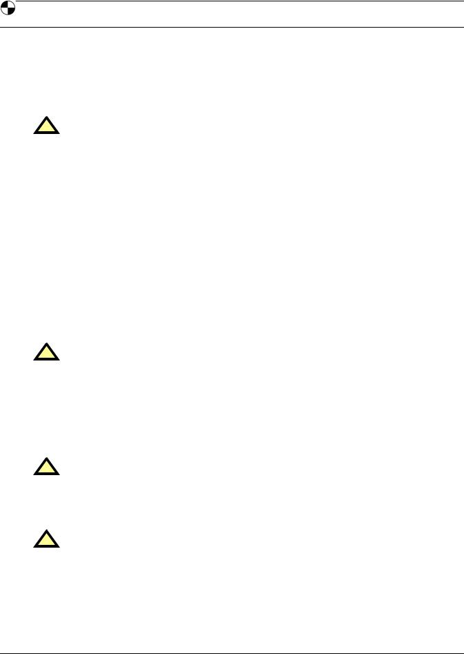
Battery cabinets may be bolted to either side of the Liebert NX; see Figure 1.
7
Installation
Figure 1 Cabinet arrangement—Liebert NX units and battery cabinets
Liebert |
Battery |
Battery |
Liebert |
|
NX |
NX |
|||
Cabinet |
Cabinet |
|||
UPS |
UPS |
|||
|
|
Front of Units |
Front of Units |
Battery |
Battery |
Battery |
Liebert |
Liebert |
Battery |
Battery |
Battery |
|
NX |
NX |
|||||||
Cabinet |
Cabinet |
Cabinet |
Cabinet |
Cabinet |
Cabinet |
|||
UPS |
UPS |
|||||||
|
|
|
|
|
|
Front of Units |
Front of Units |
Battery |
Liebert |
Battery |
Liebert |
Multi-Module |
Liebert |
Battery |
Liebert |
Battery |
|
NX |
NX |
NX |
NX |
||||||
Cabinet |
Cabinet |
Parallel Cabinet |
Cabinet |
Cabinet |
|||||
UPS |
UPS |
UPS |
UPS |
||||||
|
|
|
|
|
Front of Units
8
Installation
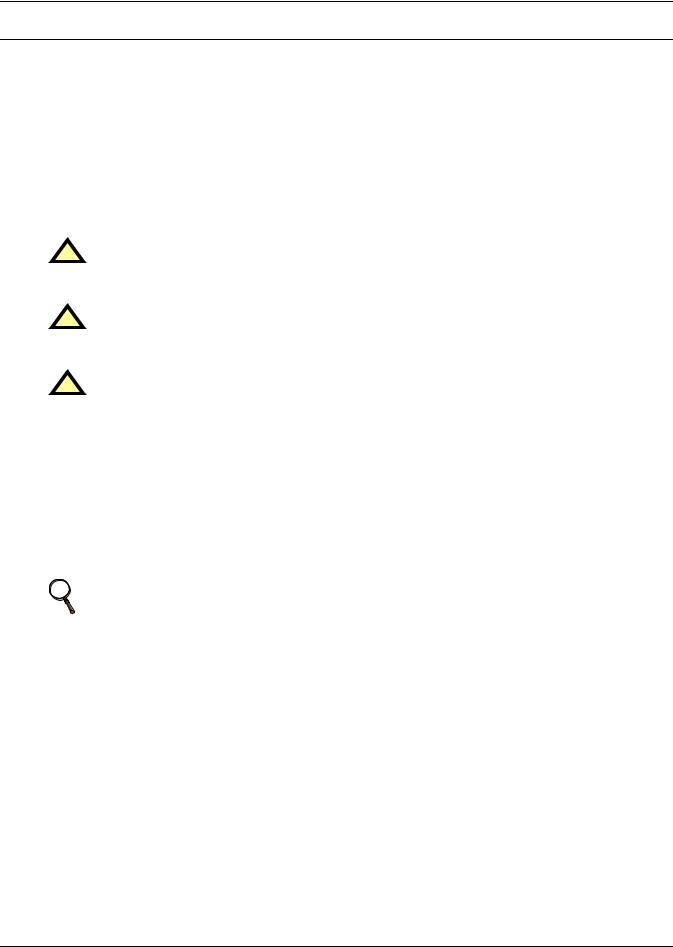
Figure 2 Cabinet arrangement—Liebert NX units, battery cabinets and Liebert FPC
|
Liebert |
Liebert |
|
|
|
Liebert |
Liebert |
|
|||
|
Foundation |
Battery |
|
Battery |
Foundation |
|
|||||
|
NX |
|
NX |
|
|||||||
|
Power |
|
Cabinet |
Cabinet |
Power |
|
|||||
|
|
UPS |
UPS |
|
|||||||
|
Center |
|
|
|
|
Center |
|
||||
|
|
|
|
|
|
|
|
||||
|
|
Front of Units |
|
|
|
Front of Units |
|
|
|||
|
|
|
Liebert |
|
Liebert |
Liebert |
Liebert |
|
|
|
|
Battery |
Battery |
Battery |
Foundation |
Foundation |
Battery |
Battery |
Battery |
||||
NX |
NX |
||||||||||
Cabinet |
Cabinet |
Cabinet |
|
Power |
Power |
Cabinet |
Cabinet |
Cabinet |
|||
UPS |
|
UPS |
|||||||||
|
|
|
|
Center |
Center |
|
|
|
|||
|
|
|
|
|
|
|
|
|
|||
|
Front of Units |
|
|
|
Front of Units |
|
|
||||
Liebert |
Multi-Module |
Liebert |
|
Liebert |
|
Liebert |
|
Liebert |
|
||
Foundation |
Battery |
Battery |
Battery |
Battery |
|||||||
Parallel |
|
NX |
NX |
NX |
NX |
||||||
Power |
|
Cabinet |
Cabinet |
Cabinet |
Cabinet |
||||||
Cabinet |
UPS |
UPS |
UPS |
UPS |
|||||||
Center |
|
|
|
|
|||||||
|
|
|
|
|
|
|
|
|
|
||
Front of Units
9

Electrical Connections
2.0ELECTRICAL CONNECTIONS
The UPS requires both power and control cabling once it has been mechanically installed. All control cables must run separate from power cables in metal conduits or metal ducts that are electrically bonded to the metalwork of the cabinets to which they are connected.
! WARNING
Before connecting input power to the Liebert NX, ensure that you are aware of the location and operation of the overcurrent protection devices that connect the UPS input/bypass supply to the power distribution panel.
De-energize and lockout or tagout all incoming highand low-voltage power circuits before installing cables or making any electrical connections.
2.1Power Cabling
2.1.1Cable Rating
The main factors affecting the choice and size of cable are voltage, current (also taking into account overcurrent), room temperature and conditions of installation of the cable.
The power cables of the system must be sized with respect to the following description:
•UPS input cables - The UPS input cables must be sized for the maximum input current, including the maximum battery recharge current, given in Table 8, with respect to the unit rating and the input AC voltage.
•UPS bypass and output cables - The bypass and output cables must be sized for the nominal output current, given in Table 8, with respect to the unit rating and the output AC voltage.
•Battery cables - When connecting an external battery cabinet, the battery cables must be sized for the battery discharge current at the end-of-discharge voltage, as given in Table 8, with respect to the unit rating.
NOTE
Table 8 gives nominal currents for determining the size of UPS power cables. Other important factors to consider include cable route length and coordination with protective devices.
The power cables can be sized to suit the UPS unit rating according to Table 8.
Lug Size and Torque Requirements
Refer to Table 24 for lug size and torque requirements.
NOTE
When installing a Liebert NX with Softscale™ capability Liebert recommends sizing the input, bypass and output cabling for the UPS’s maximum rating. Properly sizing the cable will reduce the work required to upgrade the UPS.
10
Electrical Connections
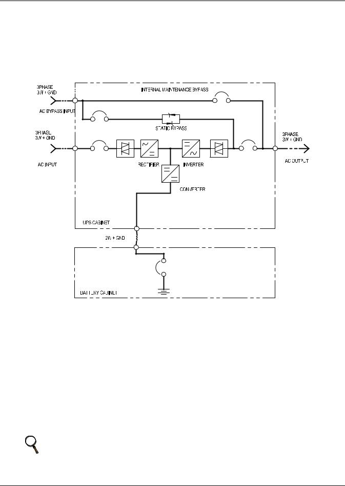
2.1.2UPS Input Configuration
Figure 3 illustrates the Liebert NX in a split bypass (dual-input) configuration. In this configuration the Static Bypass and the Maintenance Bypass lines are supplied from a separate feed from the Main input. Both sources must be protected externally with properly sized protective devices. By default, the unit ships with internal links installed between the bypass input and main input (Single Input configuration). To wire the unit as a dual input UPS, remove the links and wire the bypass to the input bus bars, then wire the Main input directly to CB1 (see Figure 4).
Figure 3 Single module block diagram—dual input configuration
2.1.3Cabling Guidelines
The following are guidelines only and are superseded by local regulations and codes of practice where applicable. Use wiring rated at 75°C or greater.
1.The ground conductor should be sized in accordance with the input overcurrent protection device data in Table 8. The ground cable connecting the UPS to the main ground system must follow the most direct route possible. Control wiring and power wiring must be run in separate conduit.
Output and input cables must be run in separate conduit.
2.Consider using paralleled smaller cables for heavy currents—this can ease installation.
3.When sizing battery cables, a maximum voltage drop of 4VDC is permissible at the current ratings in UPS terminal. For terminal connection sizing, see Table 8.
4.In most installations, especially parallel multi-module systems, the load equipment is connected to a distribution network of individually protected busbars fed by the UPS output, rather than connected directly to the UPS itself. When this is the case, the UPS output cables can be rated to suit the individual distribution network demands rather than being fully load-rated.
NOTE
If more load is added to the distribution panel, the unit’s cabling must be resized.
5.When laying power cables, do not form coils; this will help avoid increasing formation of electromagnetic interference.
11
Electrical Connections
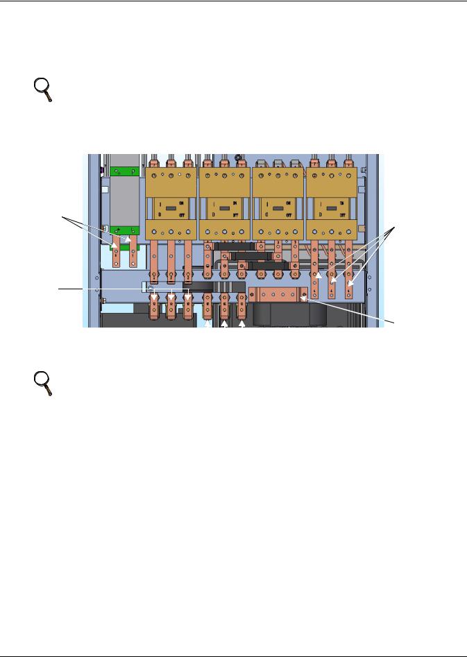
2.1.4Cable Connections
The rectifier input, bypass and output are easily accessible from the front of the unit for installation. All require lug type terminations. They are connected to busbars on the front side of the Liebert NX and below the circuit breaker, as shown in Figure 4. These busbars are accessible when the front side panel is removed. Busbars to connect external batteries are accessible from the front of the UPS.
NOTE
External connection access requires removal of a protective panel on the lower front of the UPS.
Figure 4 Input and output busbars
Battery Input
Connections
Rectifier Input Busbars (Phases are
indicated by letters below the
bars)


 Bypass Input Busbars (Phases are indicated by letters below the bars)
NOTE
Output Busbars (Phases are indicated by letters below the bars)
Ground
Busbar
There is no battery fuse in the UPS; the battery cabinet must include a circuit breaker to cut off the current in case of short circuit. Refer to Table 8 for current ratings.
12
Electrical Connections
2.1.5Safety Ground
The safety ground busbar is located below the Maintenance Bypass circuit breaker as shown in Figure 4. The safety ground cable must be connected to the ground busbar and bonded to each cabinet in the system.
All cabinets and cable conduit should be grounded in accordance with local regulations.
! WARNING
Failure to follow proper grounding procedures can result in electric shock hazard to personnel or the risk of fire, should a ground fault occur.
NOTE
Proper grounding significantly reduces electromagnetic interference problems in systems.
NOTE
The ground busbar is easily accessible when the lower protective cover plate is removed.
2.1.6Protective Devices
For safety, it is necessary to install circuit breakers in the input AC supply and external battery battery cabinets, external to the UPS system. Given that every installation has its own characteristics, this section provides guidelines for qualified installation engineers with knowledge of operating practices, regulatory standards and the equipment to be installed.
UPS Rectifier and Bypass Input Supply
•Protection from excessive overcurrents and short circuits in power supply input
External overcurrent protection for the AC output circuit is to be provided. See 5.4 - UPS Electrical Characteristics and Table 9 for overload capacity.
When an external battery supply not made by Liebert is used, the customer must provide overcurrent protection for the battery circuit.
•Dual Input
When wiring the UPS with dual inputs, the Rectifier input and the Bypass input must be protected separately. Size the breakers according to the input currents shown in Table 8. In dual input configuration, the neutral wire of each source should be connected together to guarantee dual source has the same voltage potential to earth.
13

Electrical Connections
2.1.7 Cabling Procedure
! CAUTION
The operations described in this section must be performed by authorized electricians or qualified technical personnel. If you have any difficulties, contact your local Liebert representative or Liebert Global Services.
NOTE
Hydraulic pressure pliers, combinative tools and piston ring pliers should be used to connect
AC wiring.
Once the equipment has been positioned and secured for operation, and the battery and ground collars have been connected (see 2.1.4 - Cable Connections), connect the power cables as described below. (Study the reference drawing in 6.0 - Installation Drawings.)
1.Verify that all incoming high and low voltage power circuits are de-energized and locked out or tagged out before installing cables or making any electrical connections.
2.Remove the front protective cover to gain easier access to the connections busbars.
3.Connect the safety ground and any easier bonding ground bus cables to the copper ground busbar located on the bottom of the equipment below the power connections. All cabinets in the UPS system must be connected to the user’s ground connection.
NOTE
The grounding bonding arrangement must comply with the National Electrical Code and all
applicable local codes.
4. Identify and make power connections with incoming cables according to Steps 5 through 9.
Common Input Connections
5.For common bypass and rectifier inputs, connect the AC input supply cables between the power distribution panel and the UPS input busbars (A-B-C terminals) and tighten the connections to 88 lb-in. (10 N-m) using the M8 bolt provided.
Dual Input Connections
6.For the bypass, connect the AC input supply cables between the power distribution panel and the UPS input busbars (A-B-C terminals) and tighten the connections to 88 lb-in. (10 N-m) using the M8 bolt provided.
7.For the Rectifier Input, connect AC input supply cables between the power distribution panel and the UPS input circuit breaker (A-B-C terminals).
NOTE
Both the rectifier and bypass feeds MUST come from the same utility source.
Output System Connections—Ensure Correct Phase Rotation
8.Connect the system output cables between the UPS output busbars (A-B-C terminals) and the critical load and tighten the connections to 88 lb-in. (10 N-m) (M8 bolt).
! WARNING
If the load equipment will not be ready to accept power on the arrival of the commissioning engineer, then ensure that the system output cables are safely isolated.
Observe the battery cable polarity. Be sure that the battery connector is made with the correct polarity.
9. Refit all protective covers removed for cable installation
14
Electrical Connections
Frequency Converter Mode
If a frequency converter configuration is used, connect the AC input supply cables to the rectifier input busbars (A-B-C terminals). Torque to 88 lb-in (10N-m) for M8 bolts. Ensure correct phase rotation. There will not be any AC bypass supply cables to the bypass input (A-B-C terminals) and tighten the connections.
NOTE
The operations described in this section must be performed by authorized electricians or qualified technical personnel. If any difficulties arise, contact Liebert at 1-800-LIEBERT.
NOTE
For frequency converter operation, ensure that the linking busbars between the bypass and the rectifier input are removed.
2.2Control Cables
2.2.1Monitor Board Features
Based on your site’s specific needs, the UPS may require auxiliary connections to manage the battery system (external battery circuit breaker, battery temperature sensor), communicate with a personal computer or provide alarm signaling to external devices or for Remote Emergency Power Off (REPO). The monitor board, arranged for this purpose, is located on the rear of the operator access door. The main features are:
•Input and Output dry contacts signal (one pair of contacts of relay)
•Emergency Power Off control (EPO)
•Environmental parameter input interface
•User communication (for data setting and user background monitor)
•Liebert IntelliSlot® interface
•Modem interface
•Temperature detect interface
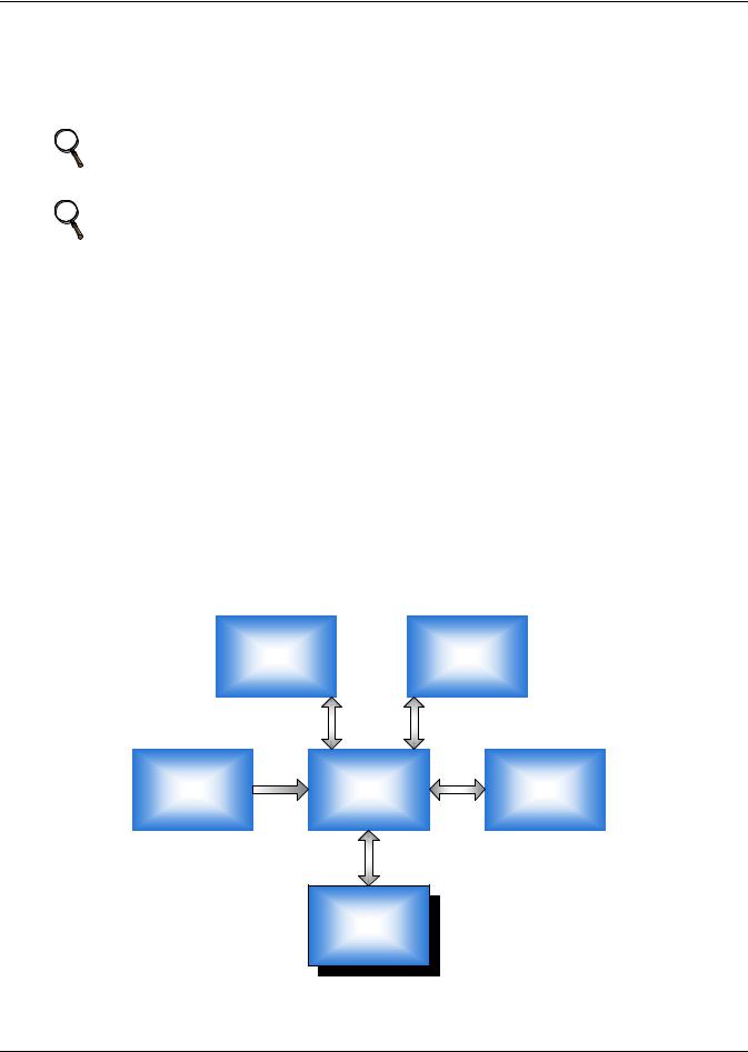
Figure 5 shows the relationship and connection between the monitoring (U2) board and other boards in the UPS.
Figure 5 Monitor board U2
|
|
|
|
|
|
|
|
U1 |
|
|
|
K1 |
|
|
DSP Control |
|
|
|
Key & LED Board |
|
|
|
|
|
|
|
|
|
|
|
|
|
|
|
|
|
|
|
|
|
|
|
|
|
|
|
M5 |
|
|
|
U2 |
|
|
|
M3 |
|
|
|
|
|
|
|
|
Parallel Logic |
|
||
|
Auxiliary Power |
|
|
|
Monitor Board |
|
|
|
|
|
|
|
|
|
|
|
|
Board |
|
||
|
|
|
|
|
|
|
|
|
|
|
|
|
|
|
|
|
|
|
|
|
|
|
|
|
|
|
|
|
|
|
|
|
X1
User Interface
Board
15
Electrical Connections
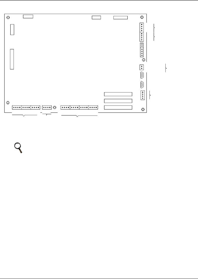
Figure 6 Auxiliary terminal block detail (Monitoring Board)
|
|
J8 |
|
|
|
|
|
|
|
|
|
|
|
|
|
|
J3 |
J1 |
|
LCD |
|
|
|
|
|
|
|
J22 |
|
|
|
|
|
|
|
|
|
||
|
|
|
|
|
|
|
|
|
J23 |
|
|
|
|
|
|
|
|
|
J12 |
J2 |
|
|
|
|
|
|
|
|
J9 |
|
|
|
|
|
|
|
|
|
|
|
|
|
|
|
|
|
|
|
J15 |
|
|
|
|
|
|
|
|
|
J16 |
|
|
|
|
|
|
|
|
|
J17 |
|
|
|
|
|
|
|
|
Liebert IntelliSlot 2 X4 |
|
J13 |
J21 |
J25 |
J28 |
J4 |
J26 |
J30 |
J10 |
Liebert IntelliSlot 1 |
J24 |
|
|||||||||
BFP |
INV ACF |
EPO |
Dry in |
MBC |
BCB |
Liebert IntelliSlot 3 |
|
||
|
|
||||||||
|
X1 |
|
X2 |
|
X3 |
|
|
|
|
|
|
|
|
|
|
|
|
||
X7
X6
PWR |
|
MODEM |
X5 |
SNMP CARD |
X4
NOTE: The black square ( ) on each slot indicates Pin 1.
2.3Dry Contacts
The UPS provides input dry contacts and output dry contacts.
NOTE
When operating the Liebert NX with dry contacts, ESD measures must be taken or the contacts may be damaged.
16

Electrical Connections
2.3.1Input Dry Contacts
There are several input dry contacts at the X3 slot.
Figure 7 Input dry contacts
+12V |
|
|
|
|
|
|
|
|
|
|
|
X3 |
J4 |
|
|
|
J26 |
|
|
|
J30 |
|
|
|
|
|
|
|
|
|
|
|
|||
+12V |
GEN |
BtG |
ENV |
GND |
+12V |
AUX I |
T IT |
AUX 0 |
T 0T |
F FAN |
FUSE |
NOTE: The black square (
Table 1 |
Input dry contacts at X3 |
|
|
|
|
Position |
Name |
Description |
|
|
|
J4.1 |
ENV3 |
Battery Room Alarm (N.C.) |
J4.2 |
BtG |
Battery Ground Fault Detection (N.C.) |
|
|
|
J4.3 |
GEN1,2 |
Generator Join Detection (N.O.) |
J4.4 |
+12V |
+12V Power |
|
|
|
+12V +12V

 +12V
+12V
|
J10 |
|
|
OL |
GND |
FB |
DRV |
) on each slot indicates Pin 1.
1 - Must be configured using configuration software before becoming active.
2 - When activated, the charger current can be limited, via software, to a percentage of the full charger current (0-100%). 3 - Activating this feature turns the battery charger off.
2.3.2Maintenance Bypass Cabinet Interface
J26 and J30 are the MBC interface.
Table 2 Maintenance bypass cabinet interface
Position |
Name |
Description |
|
|
|
J26.1 |
T_IT1 |
Input transformer over temperature (N.C.) |
J26.2 |
AUX_I |
Reserved |
|
|
|
J26.3 |
+12V |
+12V Power |
|
|
|
J26.4 |
GND |
Power Ground |
|
|
|
J30.1 |
FUSE |
Reserved |
|
|
|
J30.2 |
F_FAN |
Fan Fail Alarm (N.C.) |
|
|
|
J30.3 |
T_OT1 |
Output Transformer Overtemperature (N.C.) |
J30.4 |
AUX_O |
Reserved |
|
|
|
1 - Must be configured using configuration software before becoming active.
NOTE
All auxiliary cables of terminal must be double-insulated. Wire should be 20-16AWG stranded for maximum runs between 82 and 197 feet (25-60m), respectively.
17
Electrical Connections
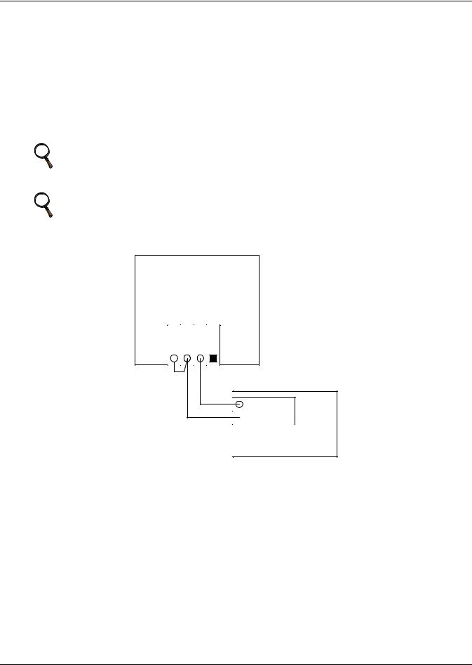
2.3.3BCB Control Interface
J10 is the BCB box interface.
Table 3 BCB control interface
Position |
Name |
Description |
|
|
|
|
|
J10.1 |
DRV |
BCB Driver Signal |
|
|
|
|
|
J10.2 |
FB |
BCB Contact State |
|
|
|
|
|
J10.3 |
GND |
Power Ground |
|
|
|
|
|
J10.4 |
OL |
BCB On-Line - Input - This pin will become active when |
|
BCB interface is connected. (N.O.) |
|||
|
|
NOTE
All auxiliary cables of terminal must be double-insulated. Wire should be 20-16AWG stranded for maximum runs between 82 and 197 feet (25-60m), respectively.
NOTE
If a BCB interface is connected and a battery interface board is not used, a jumper
needs to added between Pin 3 and Pin 4.
Figure 8 Jumper connection for BCB interface without a battery interface board
UPS Monitoring Board
J10
OLGNDFBDRV
Aux – N.O.
 Aux – N.O.
Battery Circuit Breaker
18
Electrical Connections
2.3.4Output Dry Contacts
There are three output dry contact relays at the X1 slot (see Figure 9 and Table 4).
Figure 9 Output dry contacts and EPO wiring for firmware before M170
X1
|
J13 |
|
|
J21 |
|
|
J25 |
|
BFP C |
BFP S |
BFP O |
INV C |
INV S |
INV O |
ACF C |
ACF S |
ACF O |
NOTE: The black square on each slot  indicates Pin 1.
Table 4 |
Output dry contact relays |
|
|
|
|
Position |
Name |
Description |
|
|
|
J13.2 |
BFP_O |
Bypass feedback protection relay. Normally open. Closed when bypass SCR is shorted. |
|
|
|
J13.3 |
BFP_S |
Bypass feedback protection relay center |
|
|
|
J13.4 |
BFP_C |
Bypass feedback protection relay. Normally closed. Open when bypass SCR is shorted. |
|
|
|
J21.2 |
INV_O |
Inverter mode relay. Normally open. Closed when UPS is in inverter mode. |
|
|
|
J21.3 |
INV_S |
Inverter mode relay center |
|
|
|
J21.4 |
INV_C |
Inverter mode relay. Normally closed. Open when UPS is in inverter mode. |
|
|
|
J25.2 |
ACF_O |
Main input fault relay. Normally open. Closed when main input is in fault. |
|
|
|
J25.3 |
ACF_S |
Main input fault relay center |
|
|
|
J25.4 |
ACF_C |
Main input fault relay. Normally closed. Open when main input is in fault. |
|
|
|
NOTE
All auxiliary cables of terminal must be double-insulated. Wire should be 20-16AWG stranded for maximum runs between 82 and 197 feet (25-60m), respectively.
19

Electrical Connections
2.3.5EPO Input—Optional
The UPS has an Emergency Power Off (EPO) function operated by a button on the control panel or by a remote contact provided by the user. The local EPO button is under a hinged, clear plastic shield.
The X2 slot, shown in Figure 10, is the remote EPO input interface. The EPO has a NO/NC contact point that becomes active when shorting terminals X2: 3 and 4 or open terminal connection
X2: 2 and 1.
If an external Emergency Stop facility is required, it is connected terminals X2: 1 and 2 or X2: 3 and 4 of the auxiliary terminal block (X2). It also is connected to the Normally Open or Normally Closed remote stop switch between these two terminals using shielded cable (see Figure 10 and Table 5). If this function is not used, terminals X2: 3 and 4 must be opened and X2: 1 and 2 must be closed.
Figure 10 EPO wiring
J28 |
X2 |
|
|
|
EPO - NO |
|
NOTE: The black square |
|
indicates Pin 1. |
|
|
|
|
|||
|
|
EPO - NC |
|
|
||
Table 5 |
EPO input contact relays |
|
|
|
|
|
|
|
|
|
|
|
|
Position |
Name |
Description |
|
|
|
|
|
|
|
|
|
|
|
J28.1 |
EPO_NC |
EPO Activated when opened to J28.2 |
|
|
|
|
|
|
|
|
|
|
|
J28.2 |
EPO_NC |
EPO Activated when opened to J28.1 |
|
|
|
|
|
|
|
|
|
|
|
J28.3 |
EPO_NO |
EPO Activated when shorted to J28.4 |
|
|
|
|
|
|
|
|
|
|
|
J28.4 |
EPO_NO |
EPO Activated when shorted to J28.3 |
|
|
|
|
|
|
|
|
|
|
|
NOTE
The Emergency Stop action within the UPS shuts down the rectifier, inverter and static bypass. It does not internally disconnect the input power supply. To disconnect ALL power to the UPS, open the upstream feeder breaker(s) when the remote EPO is activated.
NOTE
Normally Closed EPO – X2: 1,2, these terminals are supplied factory-linked on the monitor board and must remain installed if using NO contacts.
NOTE
All auxiliary cables of terminal must be double-insulated. Wire should be 20-16AWG stranded for maximum runs between 82 and 197 feet (25-60m), respectively.
20
Battery Installation
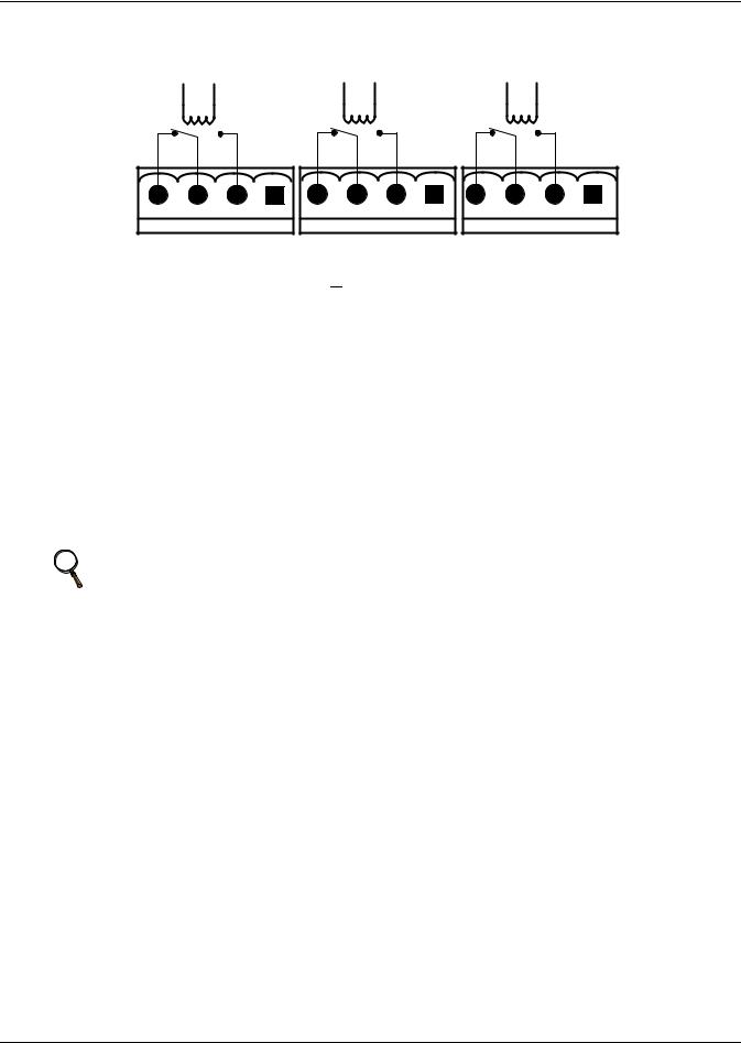
3.0BATTERY INSTALLATION
3.1Introduction
If using multiple sets of batteries connected in parallel to provide the required battery backup run times, fit each set with an isolating device to permit working on one of the battery sets while leaving the others in service and providing backup protection.
When replacing batteries, replace with the same manufacturer and type, or equivalent. See your Liebert representative for a list of approved batteries.
3.2Safety
Special care should be taken when working with the batteries associated with the Liebert NX system equipment. When all batteries are connected together, the battery terminal voltage may exceed 480V and is POTENTIALLY LETHAL.
! WARNING
The Liebert NX's internal batteries are connected and energized even if the UPS is turned Off. To minimize the risk of injury, a qualified service person should disconnect the batteries before any maintenance is performed on the unit.
A battery can present a risk of electrical shock and high short circuit current. The following precautions should be observed when working on batteries:
• Remove watches, rings and other metal objects.
• Use tools with insulated handles.
• Wear rubber gloves and boots.
• Do not lay tools or metal parts on top of batteries.
• Disconnect charging source prior to connecting or disconnecting battery terminals.
! CAUTION
To reduce the risk of fire, connect only to a circuit provided with DC amperes (see Table 12) maximum branch circuit overcurrent protection in accordance with the National Electric Code, ANSI/NFPA 70.
NOTE
The maximum available fault current from the battery supply is 8500A and the DC voltage rating of the battery supply overcurrent protective device that is to be installed near the battery supply must be at least 600VDC.
21
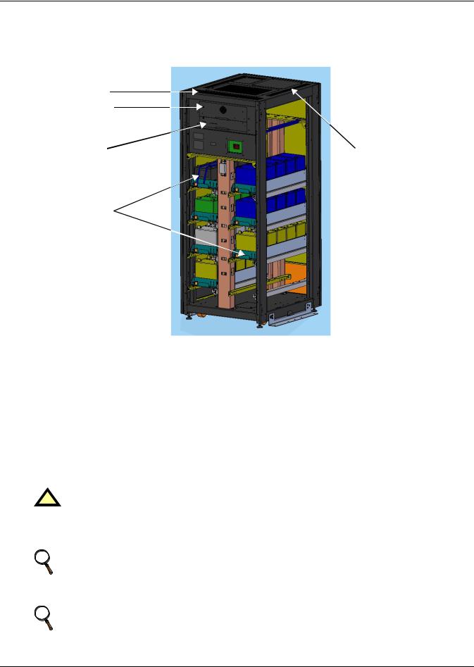
Battery Installation
3.3External Battery Cabinet Installation
3.3.1Battery Cabinets
Figure 11 Battery cabinet
Top Cable Entry
Optional Alber Data
Collector Module
Optional Alber |
BCB Plate and BCB |
|
Controller Module |
||
|
Battery Trays
The same model battery cabinet may be installed in parallel in multiple cabinet strings for additional capacity. Battery run time depends on the cabinet model, the number of cabinets and the load on the UPS.
Handling—The battery cabinet has casters to facilitate movement over short distances. The bottoms of the battery cabinets are reinforced to permit movement by forklift over longer distances.
Inspection—Remove all panels and visually inspect the batteries, bus connections and cabinet for any damage. Exercise caution: voltage is present within the battery cabinet even before installation. If there are signs of damage, do not proceed. Call Liebert Global Services at 1-800-542-2378.
Storage—The batteries can be stored for up to six months without appreciable deterioration. If planning to store a battery cabinet for longer than six months or at temperatures higher than 77°F (25°C), contact Liebert Global Services for recommended precautions.
! CAUTION
Any battery system should be installed by qualified personnel.
When installing an external battery cabinet that is NOT a Liebert NX battery cabinet, the customer must provide overcurrent protection. See Table 8 for sizing of protection devices.
NOTE
When using an external battery supply that is not provided by Liebert, refer to the battery manufacturer’s installation manual for battery installation and maintenance instructions, available on the manufacturer’s Web site.
NOTE
When replacing batteries, Liebert recommends that the all batteries in external cabinets be the same type. See Table 11 for a list of batteries that are approved for use with this product.
22
Loading...