


CF820PW00
READ AND SAVE THESE INSTRUCTIONS
Part No. F40BP73510000 Form No. BP7351
U.L. Model No.: CF820
Net Weight: 37.0 Lbs.
Model Numbers
LA FAYETTE
™
Ceiling Fan
Owner's Manual
CF820ORB00
Oil Rubbed Bronze
CF820PW00
Pewter
2
WARNING
!
WARNING: To avoid fire, shock, and serious personal injury, follow these instructions.
Safety Instructions
1. Read your owner’s manual carefully and keep it for future reference
2. Before attempting installation, servicing or cleaning unit, switch power off at service panel and lock service
panel disconnecting means to prevent power from being switched on accidentally. When the service
disconnecting means cannot be locked, securely fasten a warning device, such as a tag, to the
service panel.
3. Be careful of the fan and blades when cleaning, painting, or working near the fan. Always turn off the power
to the ceiling fan before servicing.
4. Do not put anything into the fan blades while they are turning.
Additional Safety Instructions for Installation
1. To avoid possible shock, be sure electricity is turned off at the fuse box before wiring, and do not operate
fan without blades.
2. All wiring must be in accordance with the National Electrical Code “ANSI/NFPA 70-1999” and Local Electrical
Codes. Use the National Electrical Code if Local Codes do not exist. The ceiling fan must be grounded as a
precaution against possible electrical shock. Electrical installation should be made or approved by a
licensed electrician.
3. The outlet box and joist must be securely mounted and capable of reliably supporting a least 50 pounds. Use
only U.L. outlet boxes listed as “Acceptable for Fan Support of 50 lbs. or Less”, and use the mounting
screws provided with the outlet box. Most outlet boxes commonly used for support of light fixtures are not
acceptable for fan support and may need to be replaced. Consult a qualified electrician if in doubt.
4. The longer downrod (12”) furnished with the ceiling fan provides the minimum recommended floor-to-fan
blade clearance for a 9-foot ceiling. The 6” downrod (supplied) is to be used for shorter ceilings.
5. The fan must be mounted with the fan blades at least 7 feet from the floor to prevent accidental
contact with th fan blades.
6. Follow the recommended instructions for the proper method of wiring your ceiling fan. If you do not know
enough about electrical wiring, have your fan installed by a licensed electrician.
NOTE: This fan is suitable for use with solid-state speed controls.
WARNING: To reduce the risk of fire or electric shock, this fan should only be used with fan speed control
SW105, manufactured by Rhine Electric Co., Ltd.
WARNING: To avoid fire, shock or injury, do not use an Emerson or any other brand of control not specifically
approved for this fan.
WARNING: This product is designed to use only those parts supplied with this product and/or any
accessories designated specifically for use with this product by Emerson Electric Co. Substitution of parts or
accessories not designated for use with this product by Emerson Electric Co. could result in personal injury or
property damage.
WARNING: To reduce the risk of personal injury, do not bend the blade flange when installing the blade
flanges, balancing the blades or cleaning the fan. Do not insert foreign objects in between rotating fan blades.
WARNING: To reduce the risk of electrical shock, this fan must be installed with a general use, isolating wall
control/switch.
DATE CODE:
The date code of this fan may be found on
the box, stamped in ink on a white label.
You should record this data above and keep
it in a safe place for future use.
U.L. Model No.: CF820
FOR CANADA, THIS FAN MUST BE SECURED DIRECTLY TO THE BUILDING STRUCTURE/CEILING JOIST.
DO NOT SECURE THIS FAN TO AN OUTLET BOX.
3
This Manual Is Designed to Make it as Easy as Possible for You to
Assemble, Install, Operate and Maintain Your Ceiling Fan
One stepladder
One wire stripper
One Phillips head screwdriver
Four 15-watt (max.) candelabra base bulbs (not supplied)
Three 40-watt (max.) candelabra base bulbs (not supplied)
MATERIALS
Wiring outlet box and box connectors must be of type
required by the local code. The minimum wire would
be a 3-conductor (2-wire with ground) of the wire
size, to right:
Installed Wire Length Wire Size A.W.G.
Up to 50 ft. 14
50-100 ft. 12
If you feel you do not have enough wiring knowledge or
experience, have your fan installed by a licensed
electrician.
WARNING
!
Unpacking Instructions
For your convenience, check-off boxes are provided next to each step. As each step is completed, place
a check mark in the box. This will insure that all steps have been completed and will be helpful in finding
your place should you be interrupted.
Do not install or use fan if any part is damaged or
missing. Call Toll-Free:
1-800-654-3545
This product is designed to use only those parts
supplied with this product and/or any accessories
designated specifically for use with this product by
Emerson Electric Co. Substitution of parts or
accessories not designated for use with this product
by Emerson Electric Co. could result in personal
injury or property damage.
WARNING
!
WARNING
!
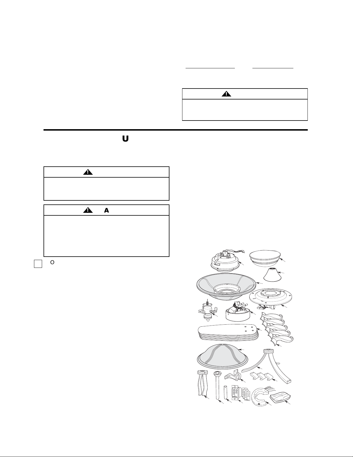
1. Open styrofoam unit containing fan. Remove upper
and center sections of styrofoam unit. Remove parts
and check to see that you have received the following:
a. One Fan Motor and Housing Assembly
b. One Ceiling Cover
c. Five Fan Blades
d. Five Flange Assemblies
e. One Coupling Cover
f. One Hanger Bracket
g. One 12” Downrod/Hanger Ball Assembly
h. One 6” Downrod
i. One Upper Light Kit Assembly
j. One Lower Light Fitter Assembly
k. One Upper Light Kit Glass Shade Assembly
l. One Lower Light Kit Glass Shade
m.One Decorative Lower Scroll
n. Three Decorative Scroll Ends
o. One Decorative Upper Scroll
p. One Switch Cup Assembly
q. One SW116 Fan/Light Wall Control
(transmitter)
r. One SW105 Receiver
s.One loose parts bag containing:
1. One 1/8-27 NPS nut
2. One split lockwasher
3. Two #8-32 x 1-1/4” threaded studs
4. Five 12GA wire nut connectors
5. Two #8-32 knurled knobs
6. Two #8 external tooth lockwashers
Tools Needed for Assembly
7. One hairpin clip
8. One clevis pin
9. Twenty-one #10-32 x 8mm pan head screws
10. Twenty-one #10 flat washers
11. Eleven 1/4-20 x 16mm oval head screws
12. Four #8-32 x 10mm flat head screws
13. Five #10-32 x 10mm flat head screws and
lockwashers
14. One balancing kit
NOTE: Place the parts from the loose parts bags
in small containers to keep them from being lost.
If any parts are missing, contact your local
retailer or catalog outlet for replacement before
proceeding.
U.L. Model No.: CF820
c.
m.
n.
q.
l.
d.
i.
j.
p.
b.
e.
k.
H
I
H
I
M
E
D
M
E
D
L
O
W
L
O
W
FAN OFF
R
E
V
R
E
V
LIGHT
f.
h.
g.
a.
s.
r.
o.
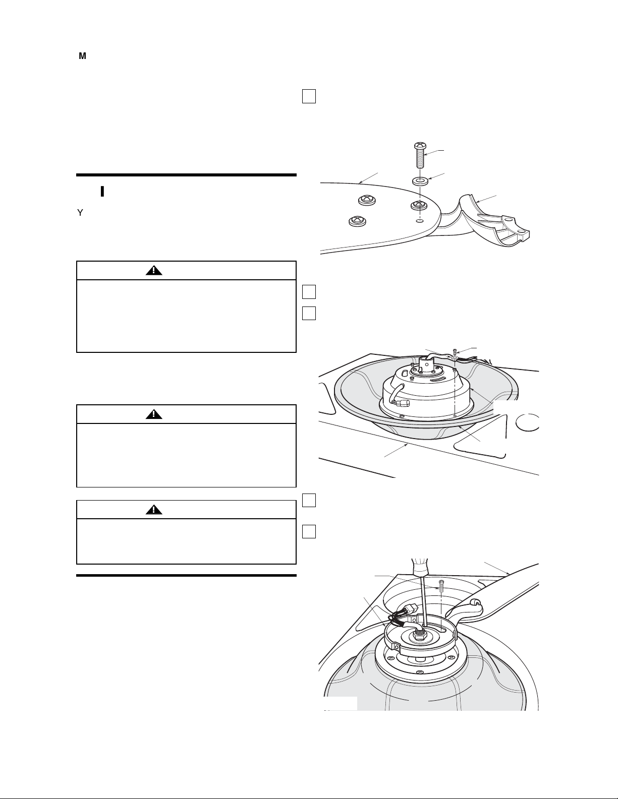
1. Place the flange onto the blade. Secure the flange
to the blade using the four #10-32 x 8mm pan
head screws and four #10 flat washers (supplied).
Repeat for the four remaining blades. (Figure 1)
2. Place the upper glass shade into the styrofoam for
fan motor assembly.
3. Attach the fan motor assembly to the upper glass
shade using the four #10-32 x 10mm pan head
screws and lockwashers (supplied) (Figure 2).
4. Carefully turn the partially assembled fan motor
upside down and place into the styrofoam for
blade assembly installation.
5. Rotate the switch housing plate to align the holes
in the blade flange assembly with the holes in the
motor housing (Figure 3).
BLADE
#10-32 x 8mm
PAN HEAD SCREW
(4 Per Blade)
#10 FLAT LOCKWASHER
(4 Per Blade)
FLANGE
ASSEMBLY
#10-32 x 10mm
PAN HEAD SCREW (4)
LOCKWASHER (4)
UPPER GLASS
SHADE
FAN MOTOR
ASSEMBLY
STYROFOAM
Figure 2
BLADE FLANGE
ASSEMBLY
SWITCH
HOUSING PLATE
1/4-20 x 16mm OVAL
HEAD SCREW (2 per
flange assembly)
Figure 3
If your fan is to replace an existing ceiling light fixture,
turn electricity off at the main fuse box at this time
and remove the existing light fixture.
Turning off wall switch is not sufficient. To avoid
possible electrical shock, be sure electricity is turned
off at the main fuse box before wiring. All wiring must
be in accordance with national and local codes and
the ceiling fan must be properly grounded as a
precaution against possible electrical shock.
WARNING
!
Your new ceiling fan will require a grounded electrical
supply line of 120 volts AC, 60 Hz, 15 amp circuit.
The outlet box must be securely anchored and
capable of withstanding a load of at least 50 pounds.
To reduce the risk of fire, electric shock, or personal
injury, mount fan to outlet box marked “Acceptable
for Fan Support of 50 lbs. or Less”, and use screws
supplied with outlet box. Most outlet boxes
commonly used for support of light fixtures are not
acceptable for fan support and may need to be
replaced. Consult a qualified electrician if in doubt.
WARNING
!
Electrical Requirements
Ceiling Fan Assembly
Procedures
To avoid possible fire or shock, follow all wiring
instructions carefully. Any electrical work not
described in these instructions should be done or
approved by a licensed electrician.
WARNING
!
4
IMPORTANT: Your ceiling fan is supplied with an
SW116 Fan/Light Wall Control (transmitter) and a
remote control SW105 Receiver which mounts
under the ceiling cover. This system allows you to
regulate your ceiling fan speed, airflow direction,
and light intensity. An optional Emerson Electric
SR110 Remote Control may also be used.
IMPORTANT: Your ceiling fan will not function
properly and may be damaged, if used with any
wall dimmer switch or control other than the
Emerson controls listed above.
Preliminary Procedures
IMPORTANT: Before assembling your ceiling fan,
refer to sections “Setting Operating Frequency of
Wall Control and Receiver” and “Installation of
Wall Control”, Page 11. These sections instruct
you how to:
a. Set the operating frequency of the fan/light wall
control and the remote control receiver.
b. Install the fan/light wall control in the wall box.
You will then be ready to proceed with the
assembly and installation of your ceiling fan.
U.L. Model No.: CF820
Figure 1
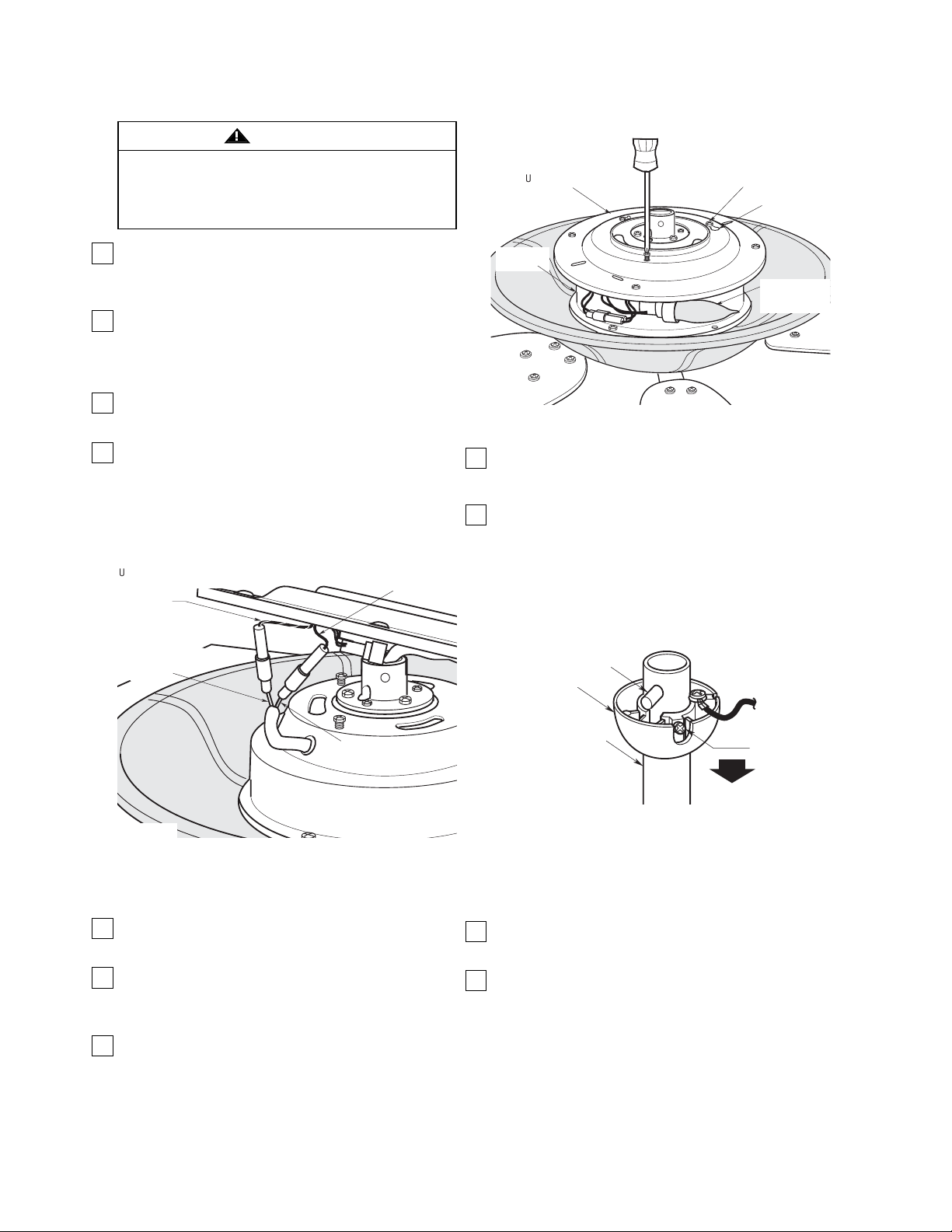
14. Obtain the hanger ball/downrod assembly and
remove the hanger ball by loosening the
setscrew in the hanger ball until the ball falls
freely down the downrod (Figure 6). Remove the
pin from the downrod, then remove the hanger
ball. Retain the pin and hanger ball for
reinstallation in Step 25. Discard the 12” downrod
if using the 6” downrod.
NOTE: The longer downrod (12”) furnished with
the ceiling fan provides the minimum
recommended floor-to-fan blade clearance for a
9-foot ceiling. The 6” downrod (supplied) is to be
used for shorter ceilings.
15. Separate, untwist and unkink the black, white and
blue motor wires and the yellow uplight lead.
Route these wires through the downrod.
16. Slide the downrod down the wires and seat the
downrod in the motor coupling (Figure 7).
5
U.L. Model No.: CF820
PIN
HANGER
BALL
SETSCREW
DOWNROD
Figure 6
NOTE: Take care not to scratch fan housing when
installing blades.
6. Loosely attach the flange assembly using two
1/4-20 x 16mm oval head screws (supplied)
(Figure 3). Install the remaining four fan blades
assemblies using the same procedure.
7. Gently snug all flange screws to the motor
housing, working around the housing in a
clockwise sequence. Failure to follow this
procedure could result in fan wobble. This
completes the blade installation.
8. Carefully turn the partially assembled fan/blade
assembly upright and rest the assembly onto the
styrofoam to continue the assembly.
9. Connect the fan motor housing yellow wire
single-pin connector to the black wire single-pin
connector from the uplight kit assembly; connect
the fan motor housing white wire single-pin
connector to the white wire single-pin connector
from the uplight kit assembly (Figure 4). Be sure all
wire connectors are fully engaged.
To reduce the risk of personal injury, do not bend the
blade flange when installing the blade flanges,
balancing the blades or cleaning the fan. Do not
insert foreign objects in between rotating fan blades.
WARNING
!
UPLIGHT KIT ASSEMBLY
WHITE WIRE SINGLE-PIN
CONNECTOR
FAN MOTOR HOUSING
WHITE WIRE SINGLE-PIN
CONNECTOR
UPLIGHT KIT ASSEMBLY
BLACK WIRE SINGLE-PIN
CONNECTOR
FAN MOTOR HOUSING
YELLOW WIRE
SINGLE-PIN CONNECTOR
Figure 4
#8-32 x 10mm FLAT
HEAD SCREW (3)
UPPER GLASS
SHADE
UPLIGHT KIT
ASSEMBLY
FAN MOTOR
HOUSING
KEYHOLE SLOT
15-WATT (max.)
CANDELABRA
LIGHT BULB (4)
Figure 5
CAUTION: Before installing and tightening the
screws, be sure there are no wires pinched
between the fan motor housing and the uplight kit
assembly.
10. Unscrew and save one of the three #8-32 x
10mm flat head screws in the fan motor housing.
(Figure 5).
11. Make sure all wires and single-pin connectors are
inside the uplight kit assembly, then position the
light kit assembly on the fan motor housing so
that the holes line up.
12. Rotate the uplight kit assembly clockwise to
engage the keyhole slots (Figure 5). Secure the
light kit assembly to the fan motor housing by
threading the previously removed screw into the
remaining hole. Tighten the three screws at this
time.
NOTE: Be sure wires and connectors are not
pinched under the uplight kit assembly before
securing the uplight kit assembly.
13. Install four 15-watt (maximum) candelabra light
bulbs (not supplied) in the uplight sockets
(Figure 5).
 Loading...