


BP7280, Olympia, KF100 7/31/06 10:57 AM Page 1
READ AND SAVE THESE INSTRUCTIONS
Emerson Fans
Designed by
OLYMPIA
Ceiling Fan Owner's Manual
Model Numbers
KF100AP01 |
KF100DBK01 |
Antique Pewter with Natural |
Distressed Black with |
Cherry/Mahogany Blades |
Distressed Black/Natural |
|
Cherry Blades |
KF100OZ01
Olde Bronze® with Teak/Olde
Bronze® Blades
Net Weight: 30.0 Lbs.
Part No. F40BP72800004 |
Form No. BP7280-4 |
|
U.L. Model No.: KF100 |
BP7280, Olympia, KF100 7/31/06 10:57 AM Page 2
!WARNING
WARNING: To avoid fire, shock, and serious personal injury, follow these instructions.
Safety Instructions
1.Read your owner’s manual carefully and keep it for future reference.
2.Before servicing or cleaning unit, switch power off at service panel and lock service panel disconnecting means to prevent power from being switched on accidentally. When the service disconnecting means cannot be locked, securely fasten a warning device, such as a tag, to the service panel.
3.Be careful of the fan and blades when cleaning, painting, or working near the fan. Always turn off the power to the ceiling fan before servicing.
4.Do not put anything into the fan blades while they are turning.
5.Do not operate reversing switch until fan blades have come to a complete stop.
Additional Safety Instructions for Installation
1.To avoid possible shock, be sure electricity is turned off at the fuse box before wiring, and do not operate fan without blades.
2.The installation is to be in accordance with the National Electrical Code, ANSI/NFPA 70-1999 and Local Electrical Codes. Use the National Electrical Code if Local Codes do not exist. The ceiling fan must be grounded as a precaution against possible electrical shock. Electrical installation should be made or approved by a licensed electrician.
3.The outlet box and joist must be securely mounted and capable of reliably supporting at least 50 pounds. Use only U.L. outlet boxes listed as “Acceptable for Fan Support”, and use the mounting screws provided with the outlet box. Most outlet boxes commonly used for support of light fixtures are not acceptable for fan support and may need to be replaced. Consult a qualified electrician if in doubt.
4.The downrod furnished with the fan provides the minimum recommended floor to fan blade clearance for an 8 foot ceiling.
5.The fan must be mounted with the fan blades at least 7 feet from the floor to prevent accidental contact with the fan blades.
6.Follow the recommended instructions for the proper method of wiring your ceiling fan. If you do not know enough about electrical wiring, have your fan installed by a licensed electrician.
NOTE: This fan is suitable for use with solid-state speed controls.
WARNING: To reduce the risk of fire or electric shock, this fan should only be used with fan speed control Model No. UC7067RC, manufactured by Rhine Electric Co., Ltd.
WARNING: This product is designed to use only those parts supplied with this product and/or any accessories designated specifically for use with this product by Emerson Electric Co. Substitution of parts or accessories not designated for use with this product by Emerson Electric Co. could result in personal injury or property damage.
WARNING: To reduce the risk of personal injury, do not bend the blade flange when installing the blade flanges, balancing the blades or cleaning the fan. Do not insert foreign objects in between rotating fan blades.
WARNING: To reduce the risk of electrical shock, this fan must be installed with an isolating wall control/switch.
DATE CODE:
The date code of this fan may be found on the box, stamped in ink on a white label. You should record this data above and keep it in a safe place for future use.
2
BP7280, Olympia, KF100 7/31/06 10:57 AM Page 3
This Manual Is Designed to Make it as Easy as Possible for You to Assemble, Install, Operate and Maintain Your Ceiling Fan
Tools Needed for Assembly
One Phillips head screwdriver One wire stripper
One stepladder
Three 60-watt (max.) candelabra base bulbs Six wire connectors (supplied)
Materials
Wiring, outlet box and box connectors must be of type required by the local code. The minimum wire would be a 3-conductor (2-wire with ground) of the following sizes:
Installed Wire Length |
Wire Size A.W.G. |
Up to 50 ft. |
14 |
50-100 ft. |
12 |
Unpacking Instructions
For your convenience, check-off boxes are provided next to each step. As each step is completed, place a check mark in the box. This will insure that all steps have been completed and will be helpful in finding your place should you be interrupted.
!WARNING
Do not install or use fan if any part is damaged or missing. Call Toll-Free:
1-800-654-3545
!WARNING
This product is designed to use only those parts supplied with this product and/or any accessories designated specifically for use with this product by Emerson Electric Co. Substitution of parts or accessories not designated for use with this product by Emerson Electric Co. could result in personal injury or property damage.

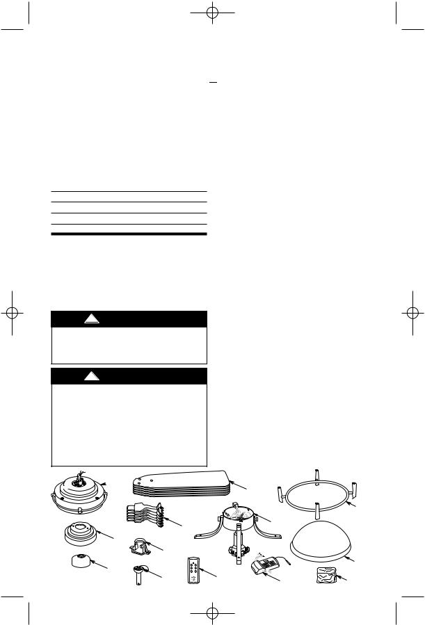
 1. Open styrofoam unit containing fan. Remove top half of styrofoam unit. Remove parts and check to see that you have received the following parts:
NOTE: If you are uncertain of part description, refer to exploded view illustration.
a.Fan motor and housing assembly
b.One ceiling cover
c.Once coupling cover
d.Five fan blades
e.Five blade flanges
f.One hanger bracket
g.One hanger ball/downrod assembly
h.One switch housing/light fitter assembly
i.One lower ring assembly (includes four mounting screws)
j.One lower glass
k.One remote control transmitter
l.One remote control receiver
m.One loose parts bag containing:
1.Two 1-1/4” threaded studs
2.Two knurled knobs
3.Two lockwashers
4.Seven wire connectors
5.One hairpin clip
6.One clevis pin
7.Eleven 1/4-20 x 11mm pan head screws with lockwashers
8.Sixteen 10-24 x 9mm truss head screws
9.Sixteen fiber washers
10.Four 8-32 x 7mm pan head screws
NOTE: Place the parts from the loose parts bags in a small container to keep them from being lost. If any parts are missing, contact your local retailer or catalog outlet for replacement before proceeding.
 A
A
|
|
D |
|
|
|
|
I |
E |
|
H |
|
|
|
|
|
B |
|
|
|
F |
|
|
|
C |
|
|
J |
K |
|
|
|
G |
L |
M |
|
3 |
|
BP7280, Olympia, KF100 7/31/06 10:57 AM Page 4

 2. Remove the fan motor and housing assembly from the protective plastic bag. Place the fan assembly into the upper foam pad with the top of the motor facing up.
The upper foam pad serves as a holder for the fan during the first stages of assembly.
Preset Memory Feature
Your remote control receiver is equipped with a preset memory feature. The receiver will remember the light intensity and fan speed when the light and fan are turned off from the wall switch. When the wall switch is turned back on, the lights and fan will resume operation as they were prior to the
General
switch being turned off.
Your Emerson ceiling fan comes equipped |
Installation of Battery |
|
with a remote control transmitter and a |
||
|
remote control receiver. This remote control systems is designed to control your ceiling fan speed, airflow direction, and light intensity.
NOTE: An optional SW113 Wall Control (not supplied) may also be used with the remote control receiver supplied with your ceiling fan.

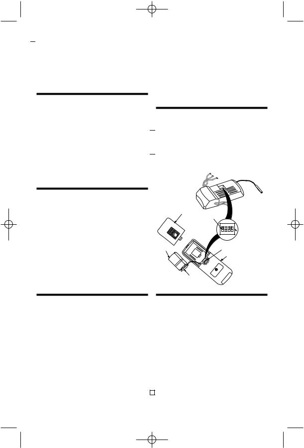
 1. Remove the battery cover by pressing firmly below the arrow and sliding the cover off the control (Figure 1).

 2. Engage the connector in the transmitter with the terminals of a 9-volt alkaline battery (not supplied).
IMPORTANT
This Owner’s Manual is divided into two sections. The first section, REMOTE CONTROL PROCEDURES, describes how to install the 9-volt alkaline battery (not supplied) in the remote control transmitter, and how to set the operating frequency of the transmitter and receiver. These instructions must be performed prior to the installation of the ceiling fan as described in the second section, CEILING FAN PROCEDURES.
BATTERY COVER
SWITCH
LEVERS
BATTERY
ON
BATTERY
CONNECTOR
Figure 1
ON |
|
|
|
1 |
2 |
3 |
4 |
 CODE
CODE
SWITCH
CODE SWITCH
REMOTE CONTROL TRANSMITTER
REMOTE CONTROL
PROCEDURES
General
The remote control system is designed to |
|
separately control your ceiling fan and |
|
light intensity. There are four push buttons |
|
on the transmitter (HI, MED, LOW, OFF) to |
|
set the fan speed and turn the fan off. The |
|
FOR/REV push button changes the airflow |
|
direction of the fan blades. The LIGHT |
|
DIMMER push button turns the lights on |
|
and off and controls the light intensity. The |
|
red indicator light will illuminate while any |
|
button is pressed, indicating that the bat- |
|
tery is good. |
4 |
Setting Operating
Frequency of Transmitter
and Receiver
Your remote control transmitter and receiver have code switches which must be set on one of 16 possible code combinations. The four levers (numbered 1, 2, 3, and 4) on the switches are factory-set in the ON (up) position. Do not use this setting. Change the switch settings as follows:
1.On the remote control transmitter, locate the code switch just above the battery compartment (Figure 1).
BP7280, Olympia, KF100 7/31/06 10:57 AM Page 5

 2. Slide the four switch levers on the code switch to your choice of ON (up) or down positions. Use a ball-point pen or small screwdriver and slide the levers firmly up or down.

 3. In the receiver (Figure 1), slide the four switch levers to the same positions as set in the transmitter. Make sure the levers on both switches are in the same positions, otherwise the fan will not operate.

 4. Position the battery in the transmitter battery compartment and replace the battery cover.
CEILING FAN
PROCEDURES
Electrical Requirements
Your new ceiling fan will require a grounded electrical supply line of 120 volts AC, 60 Hz, 15 amp circuit.
The outlet box must be securely anchored and capable of withstanding a load of at least 50 pounds.
!WARNING
To reduce the risk of fire, electric shock, or personal injury, mount fan to outlet box marked “Acceptable for Fan Support”, and use screws supplied with outlet box. Most outlet boxes commonly used for support of light fixtures are not acceptable for fan support and may need to be replaced. Consult a qualified electrician if in doubt.
!WARNING
To avoid possible fire or shock, follow all wiring instructions carefully.
Any electrical work not described in these instructions should be done or approved by a licensed electrician.
If your fan is to replace an existing ceiling light fixture, turn electricity off at the main fuse box at this time and remove the existing light fixture.
!WARNING
Turning off wall switch is not sufficient. To avoid possible electrical shock, be sure electricity is turned off at the main fuse box before wiring. All wiring must be in accordance with National and Local codes and the ceiling fan must be properly grounded as a precaution against possible electrical shock.
How to Assemble Your Ceiling Fan

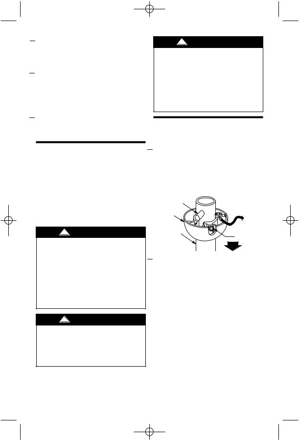
 1. Remove the hanger ball by loosening the setscrew in the hanger ball until the ball falls freely down the downrod (Figure 2). Remove the pin from the downrod, then remove the hanger ball. Retain the pin and hanger ball for reinstallation in step 5.
PIN |
|
HANGER |
|
BALL |
|
DOWNROD |
SETSCREW |
|
Figure 2

 2. Unscrew the setscrew (Figure 3) until it clears the inside of the motor coupling. Then separate, untwist and unkink the three 80” motor leads. Route the motor lead wires through the downrod. Align the clevis pin holes in the downrod with the holes in the motor coupling. Install the clevis pin and secure with the hairpin clip (Figure 3). The clevis pin must go through the holes in the motor coupling and the holes in the downrod. Be sure to push the straight leg of the hairpin clip through the hole near the end of the clevis pin until the curved portion of the hairpin clip snaps around the clevis pin. The hairpin clip must be properly installed to prevent the clevis pin from working loose. Pull up on the downrod to make sure the clevis pin is properly installed.
5
 Loading...