


 Loading...
FM-3
Programming Module
Reference Manual
P/N 400508-01
Revision: A8
Date: March 10, 2004
© Control Techniques Drives, Inc. 2000-2004

FM-3
Programming Module
Reference Manual
Information furnished by Control Techniques Drives Inc. (Control Techniques) is believed to be accurate and reliable. However, no responsibility is assumed by Control Techniques for its use. Control Techniques reserves the right to change the design or operation of the equipment described herein and any associated motion products without notice. Control Techniques also assumes no responsibility for any errors that may appear in this document. Information in this document is subject to change without notice.
P/N 400508-01
Revision: A8
Date: March 10, 2004
© Control Techniques Drives, Inc. 2000-2004

© Control Techniques Drives, Inc. 2000-2004
Part Number: 400508-01
Revision: A8
Date: March 2004
Printed in United States of America
Information in this document is subject to change without notice. No part of this document may be reproduced or transmitted in any form or by any means, electronic or mechanical, for any purpose, without the express written permission of Control Techniques.
The following are trademarks of Control Techniques and may not be reproduced in any fashion without written approval of Control Techniques: EMERSON Motion Control,
EMERSON Motion Control PowerTools, AXIMA, “Motion Made Easy.”
Control Techniques is a division of EMERSON Co.
Control Techniques, Inc. is not affiliated with Microsoft Corporation, owner of the Microsoft, Windows, and Windows NT trademarks.
This document has been prepared to conform to the current released version of the product. Because of our extensive development efforts and our desire to further improve and enhance the product, inconsistencies may exist between the product and documentation in some instances. Call your customer support representative if you encounter an inconsistency.
ii

Customer Support
Control Techniques
12005 Technology Drive
Eden Prairie, Minnesota 55344-3620
U.S.A.
Telephone: (952) 995-8000 or (800) 893-2321
It is Control Techniques’ goal to ensure your greatest possible satisfaction with the operation of our products. We are dedicated to providing fast, friendly, and accurate assistance. That is why we offer you so many ways to get the support you need. Whether it’s by phone, fax or modem, you can access Control Techniques support information 24 hours a day, seven days a week. Our wide range of services include:
FAX |
(952) 995-8099 |
You can FAX questions and comments to Control Techniques. Just send a FAX to the number listed above.
Website and Email |
www.emersonct.com |
Website: www.emersonct.com
Email: info@emersonct.com
If you have Internet capabilities, you also have access to technical support using our website. The website includes technical notes, frequently asked questions, release notes and other technical documentation. This direct technical support connection lets you request assistance and exchange software files electronically.
Technical Support |
(952) 995-8033 or (800) 893-2321 |
Email: service@emersonct.com
Control Techniques’ “Motion Made Easy” products are backed by a team of professionals who will service your installation. Our technical support center in Eden Prairie, Minnesota is ready to help you solve those occasional problems over the telephone. Our technical support center is available 24 hours a day for emergency service to help speed any problem solving. Also, all hardware replacement parts, if needed, are available through our customer service organization.
When you call, please be at your computer, with your documentation easily available, and be prepared to provide the following information:
•Product version number, found by choosing About from the Help menu
•The type of controller or product you are using
iii

•Exact wording of any messages that appear on your screen
•What you were doing when the problem occurred
•How you tried to solve the problem
Need on-site help? Control Techniques provides service, in most cases, the next day. Just call Control Techniques’ technical support center when on-site service or maintenance is required.
Training Services |
(952) 995-8000 or (800) 893-2321 |
Email: training@emersonct.com
Control Techniques maintains a highly trained staff of instructors to familiarize customers with Control Techniques’ “Motion Made Easy” products and their applications. A number of courses are offered, many of which can be taught in your plant upon request.
Application Engineering |
(952) 995-8000 or (800) 893-2321 |
Email: applengr@emersonct.com
An experienced staff of factory application engineers provides complete customer support for tough or complex applications. Our engineers offer you a broad base of experience and knowledge of electronic motion control applications.
Customer Service (Sales) |
(952) 995-8000 or (800) 893-2321 |
Email: customer.service@emersonct.com
Authorized Control Techniques distributors may place orders directly with our Customer Service department. Contact the Customer Service department at this number for the distributor nearest you.
Document Conventions
Manual conventions have been established to help you learn to use this manual quickly and easily. As much as possible, these conventions correspond to those found in other Microsoft® Windows® compatible software documentation.
Menu names and options are printed in bold type: the File menu.
Dialog box names begin with uppercase letters: the Axis Limits dialog box.
Dialog box field names are in quotes: “Field Name.”
Button names are in italic: OK button.
Source code is printed in Courier font: Case ERMS.
iv

In addition, you will find the following typographic conventions throughout this manual.
This |
Represents |
|
|
|
|
bold |
Characters that you must type exactly as they appear. For example, if you are directed to type |
|
a:setup, you should type all the bold characters exactly as they are printed. |
||
|
||
|
|
|
italic |
Placeholders for information you must provide. For example, if you are directed to type |
|
filename, you should type the actual name for a file instead of the word shown in italic type. |
||
|
||
|
|
|
ALL CAPITALS |
Directory names, file names, key names, and acronyms. |
|
|
|
|
SMALL CAPS |
Non-printable ASCII control characters. |
|
|
|
|
KEY1+KEY2 |
A plus sign (+) between key names means to press and hold down the first key while you press |
|
example: (Alt+F) |
the second key. |
|
|
|
|
KEY1,KEY2 |
A comma (,) between key names means to press and release the keys one after the other. |
|
example: (Alt,F) |
||
|
||
|
|
Note
For the purpose of this manual and product, “Note” indicates essential information about the product or the respective part of the manual.
EN EN Only
For the purpose of this manual and product, the “EN” symbol indicates information about the EN drive specifically.
Throughout this manual, the word “drive” refers to an EN or MDS drive.
“Warning” indicates a potentially hazardous situation that, if not avoided, could result in death or serious injury.
“Caution” indicates a potentially hazardous situation that, if not avoided, may result in minor or moderate injury.
“Caution” used without the safety alert symbol indicates a potentially hazardous situation that, if not avoided, may result in property damage.
v

Safety Instructions
General Warning
Failure to follow safe installation guidelines can cause death or serious injury. The voltages used in the product can cause severe electric shock and/or burns and could be lethal. Extreme care is necessary at all times when working with or adjacent to the product. The installation must comply with all relevant safety legislation in the country of use.
Qualified Person
For the purpose of this manual and product, a “qualified person” is one who is familiar with the installation, construction and operation of the equipment and the hazards involved. In addition, this individual has the following qualifications:
•Is trained and authorized to energize, de-energize, clear and ground and tag circuits and equipment in accordance with established safety practices.
•Is trained in the proper care and use of protective equipment in accordance with established safety practices.
•Is trained in rendering first aid.
Reference Materials
The following related reference and installation manuals may be useful with your particular system.
•Function Module Installation Manual (P/N 400506-03)
•Epsilon Eb and EN Drives Reference Manual (P/N 400501-01)
•PowerTools Software User’s Guide (P/N 400503-01)
•FM-3 and FM-4 Connectivity Modules Reference Manual (P/N 400508-04)
•Modular Drive System (MDS) Reference Manual (P/N 400525-01)
vi

Safety Considerations
Safety Precautions
This product is intended for professional integration into a complete system. If you install the product incorrectly, it may present a safety hazard. The product and system may use high voltages and currents, carry a high level of stored electrical energy, or control mechanical equipment that can cause injury.
You should give close attention to the electrical installation and system design to avoid hazards either in normal operation or in the event of equipment malfunction. System design, installation, commissioning and maintenance must be carried out by personnel who have the necessary training and experience. Read and follow this safety information and the instruction manual carefully.
Enclosure
This product is intended to be mounted in an enclosure which prevents access except by trained and authorized personnel, and which prevents the ingress of contamination. This product is designed for use in an environment classified as pollution degree 2 in accordance with IEC664-1. This means that only dry, non-conducting contamination is acceptable.
Setup, Commissioning and Maintenance
It is essential that you give careful consideration to changes to drive settings. Depending on the application, a change could have an impact on safety. You must take appropriate precautions against inadvertent changes or tampering. Restoring default parameters in certain applications may cause unpredictable or hazardous operation.
Safety of Machinery
Within the European Union all machinery with which this product is used must comply with Directive 89/392/EEC, Safety of Machinery.
The product has been designed and tested to a high standard, and failures are very unlikely. However the level of integrity offered by the product’s control function – for example stop/ start, forward/reverse and maximum speed – is not sufficient for use in safety-critical applications without additional independent channels of protection. All applications where malfunction could cause injury or loss of life must be subject to a risk assessment, and further protection provided where needed.
General warning
Failure to follow safe installation guidelines can cause death or serious injury. The voltages used in this unit can cause severe electric shock and/or burns, and could be lethal. Extreme care is necessary at all times when working with or adjacent to this equipment. The installation must comply with all
vii

relevant safety legislation in the country of use.
AC supply isolation device
The AC supply must be removed from the drive using an approved isolation device or disconnect before any servicing work is performed, other than adjustments to the settings or parameters specified in the manual. The drive contains capacitors which remain charged to a potentially lethal voltage after the supply has been removed. Allow at least 3 minutes after removing the supply before carrying out any work which may involve contact with electrical connections to the drive.
Products connected by plug and socket
A special hazard may exist where the drive is incorporated into a product which is connected to the AC supply by a plug and socket. When unplugged, the pins of the plug may be connected to the drive input, which is only separated from the charge stored in the bus capacitor by semiconductor devices. To avoid any possibility of electric shock from the pins, if they are accessible, a means must be provided for automatically disconnecting the plug from the drive (that is, a latching contactor).
Grounding (Earthing, equipotential bonding)
The drive must be grounded by a conductor sufficient to carry all possible fault current in the event of a fault. The ground connections shown in the manual must be followed.
Fuses
Fuses or over-current protection must be provided at the input in accordance with the instructions in the manual.
Isolation of control circuits
The installer must ensure that the external control circuits are isolated from human contact by at least one layer of insulation rated for use at the applied AC supply voltage.
viii
|
Table of Contents |
Introduction |
1 |
Operational Overview |
3 |
Software Interface . . . . . . . . . . . . . . . . . . . . . . . . . . . . . . . . . . . . . . . . . . . . . . . . . . . . . . . . . . . . . 3
PowerTools Pro Setup Software . . . . . . . . . . . . . . . . . . . . . . . . . . . . . . . . . . . . . . . . . . . . . . . . . . 3
Keypad Interface . . . . . . . . . . . . . . . . . . . . . . . . . . . . . . . . . . . . . . . . . . . . . . . . . . . . . . . . . . . . . . 4
How Motion Works . . . . . . . . . . . . . . . . . . . . . . . . . . . . . . . . . . . . . . . . . . . . . . . . . . . . . . . . . . . . 7
How Jogging Works . . . . . . . . . . . . . . . . . . . . . . . . . . . . . . . . . . . . . . . . . . . . . . . . . . . . . . . . . . . 7
How Home Works . . . . . . . . . . . . . . . . . . . . . . . . . . . . . . . . . . . . . . . . . . . . . . . . . . . . . . . . . . . . . 8
How Indexes Work . . . . . . . . . . . . . . . . . . . . . . . . . . . . . . . . . . . . . . . . . . . . . . . . . . . . . . . . . . . 18
How Communications Work . . . . . . . . . . . . . . . . . . . . . . . . . . . . . . . . . . . . . . . . . . . . . . . . . . . . 23
Brake Operation. . . . . . . . . . . . . . . . . . . . . . . . . . . . . . . . . . . . . . . . . . . . . . . . . . . . . . . . . . . . . . 29
Setting Up Parameters |
31 |
Setup View. . . . . . . . . . . . . . . . . . . . . . . . . . . . . . . . . . . . . . . . . . . . . . . . . . . . . . . . . . . . . . . . . . 31
Status Online Tab (Online Only). . . . . . . . . . . . . . . . . . . . . . . . . . . . . . . . . . . . . . . . . . . . . . . . . 34
Information Tab (Online Only) . . . . . . . . . . . . . . . . . . . . . . . . . . . . . . . . . . . . . . . . . . . . . . . . . . 37
User Units View . . . . . . . . . . . . . . . . . . . . . . . . . . . . . . . . . . . . . . . . . . . . . . . . . . . . . . . . . . . . . 38
Master Units View. . . . . . . . . . . . . . . . . . . . . . . . . . . . . . . . . . . . . . . . . . . . . . . . . . . . . . . . . . . . 42
Position View. . . . . . . . . . . . . . . . . . . . . . . . . . . . . . . . . . . . . . . . . . . . . . . . . . . . . . . . . . . . . . . . 46
Velocity View . . . . . . . . . . . . . . . . . . . . . . . . . . . . . . . . . . . . . . . . . . . . . . . . . . . . . . . . . . . . . . . 50
Ramps View. . . . . . . . . . . . . . . . . . . . . . . . . . . . . . . . . . . . . . . . . . . . . . . . . . . . . . . . . . . . . . . . . 52
Torque View . . . . . . . . . . . . . . . . . . . . . . . . . . . . . . . . . . . . . . . . . . . . . . . . . . . . . . . . . . . . . . . . 54
Tuning View . . . . . . . . . . . . . . . . . . . . . . . . . . . . . . . . . . . . . . . . . . . . . . . . . . . . . . . . . . . . . . . . 56
Faults View . . . . . . . . . . . . . . . . . . . . . . . . . . . . . . . . . . . . . . . . . . . . . . . . . . . . . . . . . . . . . . . . . 59
PLS View. . . . . . . . . . . . . . . . . . . . . . . . . . . . . . . . . . . . . . . . . . . . . . . . . . . . . . . . . . . . . . . . . . . 61
Setup NVM View . . . . . . . . . . . . . . . . . . . . . . . . . . . . . . . . . . . . . . . . . . . . . . . . . . . . . . . . . . . . 64
User Variables View . . . . . . . . . . . . . . . . . . . . . . . . . . . . . . . . . . . . . . . . . . . . . . . . . . . . . . . . . . 65
User Bits View. . . . . . . . . . . . . . . . . . . . . . . . . . . . . . . . . . . . . . . . . . . . . . . . . . . . . . . . . . . . . . . 67
I/O Setup Group. . . . . . . . . . . . . . . . . . . . . . . . . . . . . . . . . . . . . . . . . . . . . . . . . . . . . . . . . . . . . . 72
Assignments. . . . . . . . . . . . . . . . . . . . . . . . . . . . . . . . . . . . . . . . . . . . . . . . . . . . . . . . . . . . . . . . . 72
Assignments View . . . . . . . . . . . . . . . . . . . . . . . . . . . . . . . . . . . . . . . . . . . . . . . . . . . . . . . . . . . . 72
Selector View. . . . . . . . . . . . . . . . . . . . . . . . . . . . . . . . . . . . . . . . . . . . . . . . . . . . . . . . . . . . . . . . 77
Input Lines View . . . . . . . . . . . . . . . . . . . . . . . . . . . . . . . . . . . . . . . . . . . . . . . . . . . . . . . . . . . . . 81
Output Lines View. . . . . . . . . . . . . . . . . . . . . . . . . . . . . . . . . . . . . . . . . . . . . . . . . . . . . . . . . . . . 82
Analog Inputs View. . . . . . . . . . . . . . . . . . . . . . . . . . . . . . . . . . . . . . . . . . . . . . . . . . . . . . . . . . . 83
Motion Group . . . . . . . . . . . . . . . . . . . . . . . . . . . . . . . . . . . . . . . . . . . . . . . . . . . . . . . . . . . . . . . 85
ix

Jog View . . . . . . . . . . . . . . . . . . . . . . . . . . . . . . . . . . . . . . . . . . . . . . . . . . . . . . . . . . . . . . . . . . . 86
Home View . . . . . . . . . . . . . . . . . . . . . . . . . . . . . . . . . . . . . . . . . . . . . . . . . . . . . . . . . . . . . . . . . 91
Index View . . . . . . . . . . . . . . . . . . . . . . . . . . . . . . . . . . . . . . . . . . . . . . . . . . . . . . . . . . . . . . . . . 96
Gearing View . . . . . . . . . . . . . . . . . . . . . . . . . . . . . . . . . . . . . . . . . . . . . . . . . . . . . . . . . . . . . . 107
Stopping Motion . . . . . . . . . . . . . . . . . . . . . . . . . . . . . . . . . . . . . . . . . . . . . . . . . . . . . . . . . . . . 110
Network Group . . . . . . . . . . . . . . . . . . . . . . . . . . . . . . . . . . . . . . . . . . . . . . . . . . . . . . . . . . . . . 111
Modbus View . . . . . . . . . . . . . . . . . . . . . . . . . . . . . . . . . . . . . . . . . . . . . . . . . . . . . . . . . . . . . . 111
DeviceNet View . . . . . . . . . . . . . . . . . . . . . . . . . . . . . . . . . . . . . . . . . . . . . . . . . . . . . . . . . . . . 113
Profibus View . . . . . . . . . . . . . . . . . . . . . . . . . . . . . . . . . . . . . . . . . . . . . . . . . . . . . . . . . . . . . . 113
Ethernet View . . . . . . . . . . . . . . . . . . . . . . . . . . . . . . . . . . . . . . . . . . . . . . . . . . . . . . . . . . . . . . 113
Programming |
115 |
Program Toolbar Icons . . . . . . . . . . . . . . . . . . . . . . . . . . . . . . . . . . . . . . . . . . . . . . . . . . . . . . . 116
Programs . . . . . . . . . . . . . . . . . . . . . . . . . . . . . . . . . . . . . . . . . . . . . . . . . . . . . . . . . . . . . . . . . . 119
Program Instruction Types . . . . . . . . . . . . . . . . . . . . . . . . . . . . . . . . . . . . . . . . . . . . . . . . . . . . 119
Adding and Deleting Programs . . . . . . . . . . . . . . . . . . . . . . . . . . . . . . . . . . . . . . . . . . . . . . . . . 131
Run Anytime Programs. . . . . . . . . . . . . . . . . . . . . . . . . . . . . . . . . . . . . . . . . . . . . . . . . . . . . . . 132
Example Programs . . . . . . . . . . . . . . . . . . . . . . . . . . . . . . . . . . . . . . . . . . . . . . . . . . . . . . . . . . 134
Parameter Descriptions |
143 |
Installation |
183 |
Basic Installation Notes. . . . . . . . . . . . . . . . . . . . . . . . . . . . . . . . . . . . . . . . . . . . . . . . . . . . . . . 183
Mechanical Installation . . . . . . . . . . . . . . . . . . . . . . . . . . . . . . . . . . . . . . . . . . . . . . . . . . . . . . . 183
Software Installation . . . . . . . . . . . . . . . . . . . . . . . . . . . . . . . . . . . . . . . . . . . . . . . . . . . . . . . . . 185
Starting and Exiting PowerTools . . . . . . . . . . . . . . . . . . . . . . . . . . . . . . . . . . . . . . . . . . . . . . . 186
Accessing Help . . . . . . . . . . . . . . . . . . . . . . . . . . . . . . . . . . . . . . . . . . . . . . . . . . . . . . . . . . . . . 187
Quick Start |
189 |
Basic Setup Steps . . . . . . . . . . . . . . . . . . . . . . . . . . . . . . . . . . . . . . . . . . . . . . . . . . . . . . . . . . |
. 189 |
Example Application Start Up . . . . . . . . . . . . . . . . . . . . . . . . . . . . . . . . . . . . . . . . . . . . . . . . |
. 205 |
Tuning Procedures |
213 |
PID vs. State-Space . . . . . . . . . . . . . . . . . . . . . . . . . . . . . . . . . . . . . . . . . . . . . . . . . . . . . . . . . . 213 Tuning Procedure . . . . . . . . . . . . . . . . . . . . . . . . . . . . . . . . . . . . . . . . . . . . . . . . . . . . . . . . . . . 214 Tuning Parameters. . . . . . . . . . . . . . . . . . . . . . . . . . . . . . . . . . . . . . . . . . . . . . . . . . . . . . . . . . . 216 Determining Tuning Parameter Values. . . . . . . . . . . . . . . . . . . . . . . . . . . . . . . . . . . . . . . . . . . 218
x

Diagnostics and Troubleshooting |
225 |
Diagnostic Display. . . . . . . . . . . . . . . . . . . . . . . . . . . . . . . . . . . . . . . . . . . . . . . . . . . . . . . . . . . 225
Fault Codes . . . . . . . . . . . . . . . . . . . . . . . . . . . . . . . . . . . . . . . . . . . . . . . . . . . . . . . . . . . . . . . . 226
Analog Outputs . . . . . . . . . . . . . . . . . . . . . . . . . . . . . . . . . . . . . . . . . . . . . . . . . . . . . . . . . . . . . 234
Diagnostic Analog Output Test Points . . . . . . . . . . . . . . . . . . . . . . . . . . . . . . . . . . . . . . . . . . . 236
Drive Faults . . . . . . . . . . . . . . . . . . . . . . . . . . . . . . . . . . . . . . . . . . . . . . . . . . . . . . . . . . . . . . . . 238
Error Messages . . . . . . . . . . . . . . . . . . . . . . . . . . . . . . . . . . . . . . . . . . . . . . . . . . . . . . . . . . . . . 238
Programming Error Messages . . . . . . . . . . . . . . . . . . . . . . . . . . . . . . . . . . . . . . . . . . . . . . . . . . 240
Online Status Indicators. . . . . . . . . . . . . . . . . . . . . . . . . . . . . . . . . . . . . . . . . . . . . . . . . . . . . . . 245
Specifications |
249 |
Dimensions and Clearances. . . . . . . . . . . . . . . . . . . . . . . . . . . . . . . . . . . . . . . . . . . . . . . . . . |
. . 249 |
Cable Diagrams . . . . . . . . . . . . . . . . . . . . . . . . . . . . . . . . . . . . . . . . . . . . . . . . . . . . . . . . . . . . |
. 251 |
Glossary |
265 |
Index |
273 |
xi

xii
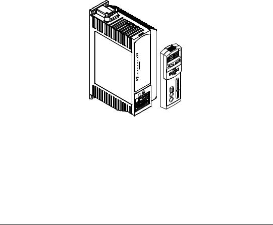
Introduction
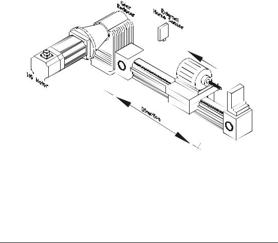
The FM-3 module is a compact and rugged function module that attaches to the front of the drive. It provides eight digital input lines and four digital output lines, in addition to the four input and three output lines available on the drive.
Unlike other function modules, the FM-3 module offers complex motion profiling. A complex motion profile consists of two or more indexes that are executed in sequence such that the final velocity of each index except the last is non-zero. Logical instructions between index statements can provide a powerful tool for altering motion profiles "on the fly". The FM-3 module defines complex motion by a configuration file that includes setups, function
assignments and programs. The configuration file is created using PowerTools Pro software1. Setup views have the same look and feel as dialog boxes. The wiring of input and output functions is done through assignments in the software. PowerTools Pro is an easy-to-use Microsoft® Windows® based setup and diagnostics tool.
Figure 1: EN Drive with FM-3 Function Module
Note that the drive’s firmware is disabled whenever a Function Module such as the FM-3 module is attached. Therefore, if the drive’s hardware is FM compatible, then the drive’s firmware can be any version because the programming features reside in the function module’s flash memory. Flash files used for firmware upgrades are available on the Control Techniques webpage.
The FM-3 module stores drive setup parameters within the module itself. This allows you to transfer the FM-3 module to another drive without losing setup parameters.
1.In this manual, Emerson Motion Control PowerTools Pro software will be referred to as PowerTools Pro.
1
FM-3 Programming Module Reference Manual
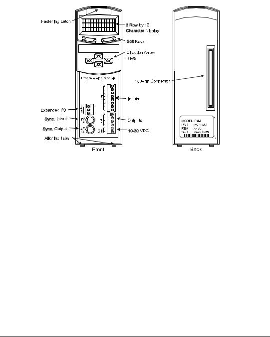
Figure 2: FM-3 Programming Module Features
2

Operational Overview
This section provides a complete functional description of the FM-3. It is intended to provide you with a thorough understanding of all operations. The description includes references to many FM-3 module and drive parameters which can be displayed and/or edited using PowerTools Pro software, or through any Modbus interface.
The FM-3 module augments the drive by providing the ability to implement programs written using PowerTools Pro. When a FM-3 module is attached to an drive, it overrides the operation and user accessible features of the drive. The drive’s basic operating modes (Pulse, Velocity and Torque) are not available when a FM-3 module is attached.
The FM-3 module stores drive setup parameters within the module itself. This allows you to transfer the FM-3 module to another drive without losing setup parameters.
The FM-3 module allows you to set up 55 different indexes, Jog functions and multiple Homes. It also provides eight digital input lines and four digital output lines in addition to the four input and three output lines available on the drive.
Software Interface
The FM-3 module is set up using PowerTools Pro software. PowerTools Pro is an easy-to-use Windows® based setup and diagnostics tool. It provides you with the ability to create, edit and maintain your drive’s setup. You can download or upload your setup data to or from a device. You can also save it to a file on your PC or print it for review or permanent storage.
PowerTools Pro Setup Software
PowerTools Pro is designed to be the easiest to use software available for single axis motion controllers.
Features
•“Hierarchy View” for quick navigation to any setup screen
•Simple I/O function assignments
•Powerful online diagnostic capabilities
•Programming
3
FM-3 Programming Module Reference Manual
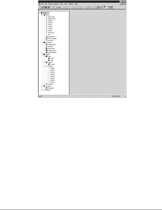
Figure 3: Hierarchy View
The “Hierarchy View” (shown above) contains expandable groups of parameters. The groups can be expanded and contracted just like folders in Windows Explorer. Left clicking on a view name in the Hierarchy view displays that View on the right side of the computer screen.
To setup a drive the user simply steps through the Hierarchy View from top to bottom. Simple applications can be setup in a matter of minutes. Many of the views have Assignment tabs that display the assignments pertaining to the view (i.e. on the Position view, the position assignments are displayed).
Keypad Interface
The keypad on the front of the FM-3 module provides navigation through a menu of common parameters and displays of current functions. Navigation through the menu is accomplished with the six keys located below the display. The top two keys are called the "soft keys" because they relate to the commands located directly above each key on the LCD. These keys are used to select the operation (e.g. Modify, Ok, Cancel), parameter group, and/or to validate information. The four arrow keys are used to navigate through parameter groups, select a specific parameter to be modified, and to modify digital and numeric data.
The operation of the arrow keys is dependent upon the type of parameter which is being modified.
4
Operational Overview
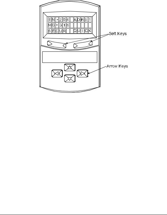
Figure 4: FM-3 Display Screen and Keypad
On the Menu screen, the drive type and axis address are always shown on the top line of the display. The second line shows the motor type. If a user defined motor is selected, the user defined motor name will appear. The third line shows two parameter group names, one above each of the soft keys.
From the Menu screen, the user selects a group of drive parameters to work with. The group names are scrolled using the left/right direction keys. The groups correspond roughly to the tabs used by the PowerTools software. The groups are shown cyclically and wrap around.
The drive parameters available with the FM-3 keypad are arranged into seven groups (see list below). Upon power-up the FM-3 module will display the default parameter groups “SECUR” (left soft key) and “QUICK” (right soft key).
•QUICK (Quick)
•PROG (Program)
•INDEX (Index)
•HOME (Home)
•JOG (Jog)
•RAMPS (Ramps)
•SECUR (Security)
5
FM-3 Programming Module Reference Manual
PBus-
Group
Slave Address
MODIF MENU
Security: 1
Baud Rate
MENU
Security: 0
Network Sts
MENU
Security: 0
Module Sts
MODIF MENU
Security: 0
MasterAddr
MENU
Security: 0
MsgProcessed
MENU
Security: 0
DVNET+
Group
MacID
MODIF MENU
Security: 1
Baud Rate
MODIF MENU
Security: 1
Network Sts
MODIF MENU
Security: 0
Module Sts
MENU
Security: 0
Net OK
MENU
Security: 0
Conn Type
MENU
Security: 0
Mster MacID
MENU
Security: 0
Transmit Cntr
MENU
Security: 0
Receive Cntr
MENU
Security: 0
Menu
Screen
EN-204 Adr01
MG-316
SECUR
SECUR |
|
RAMPS |
|
JOG* |
|
HOME |
|
INDEX* |
|
PROG* |
||||||
Group |
|
Group |
|
Group |
|
Group |
|
Group |
|
Group |
||||||
|
|
|
|
|
|
|
|
|
|
|
|
|
||||
Auto Log Out |
|
Stop |
|
|
<Jog.0.Vel> |
|
Home.0.Vel |
|
<Ind.0.Vel> |
|
<Prg.0.Init> |
|||||
MODIF |
MENU |
|
MODIF |
MENU |
|
MODIF |
MENU |
|
MODIF |
MENU |
|
MODIF |
MENU |
|
MODIF MENU |
|
|
|
|
|
|
Security: 1 |
|||||||||||
Security: 3 |
|
|
Security: 0 |
|
|
Security: 1 |
|
|
Security: 1 |
|
|
|
Security: 1 |
|
|
|
|
|
|
|
|
|
|
|
|
|
|
|
|||||
|
|
|
|
|
|
|
|
|
|
|
|
|
|
|
|
|
Password 1 |
|
Stop.Decel |
|
<Jog.0.Accl> |
|
Home.0.Accl |
|
<Ind.0.Accl> |
|
|
||||||
MODIF |
MENU |
|
MODIF |
MENU |
|
MODIF |
MENU |
|
MODIF |
MENU |
|
MODIF |
MENU |
|
|
|
Security: 3 |
|
|
Security: 1 |
|
|
Security: 1 |
|
|
Security: 1 |
|
|
|
Security: 1 |
|
|
|
|
|
|
|
|
|
|
|
|
|
|
|
|
|
|
|
|
Password 2 |
|
|
|
|
<Jog.0.Decl> |
|
Home.0.Decl |
|
<Ind.0.Decl> |
|
|
|||||
MODIF |
MENU |
|
|
|
|
MODIF |
MENU |
|
MODIF |
MENU |
|
MODIF |
MENU |
|
|
|
Security: 3 |
|
|
|
|
|
Security: 1 |
|
|
Security: 1 |
|
|
|
Security: 1 |
|
|
|
|
|
|
|
|
|
|
|
|
|
|
|
|
||||
Log Out Now? |
|
|
|
|
<Jog.0.Plus> |
|
Home.0.Init |
|
<Ind.0.Dist> |
|
|
|||||
OK |
|
|
|
|
|
MODIF |
MENU |
|
MODIF |
MENU |
|
MODIF |
MENU |
|
|
|
Security: 0 |
|
|
|
|
|
Security: 1 |
|
|
Security: 1 |
|
|
|
|
|
|
|
|
|
|
|
|
|
|
|
|
Security: 1 |
|
|
|
||||
|
|
|
|
|
|
|
|
|
|
|
|
|
|
|
|
|
|
|
|
|
|
|
<Jog.0.Mius> |
|
Calc Offset |
|
<Ind.0.Init> |
|
|
||||
|
|
|
|
|
|
MODIF |
MENU |
|
|
MENU |
|
MODIF |
MENU |
|
|
|
|
|
|
|
|
|
Security: 1 |
|
|
Security: 1 |
|
|
|
Security: 1 |
|
|
|
|
|
|
|
|
|
|
|
|
|
|
|
|
|
|
||
|
|
|
|
|
|
Posn Fdbk Ct |
|
Spec Offset |
|
|
|
|
|
|
||
|
|
|
|
|
|
|
MENU |
|
MODIF |
MENU |
|
|
|
|
|
|
|
|
|
|
|
|
Security: 0 |
|
|
|
|
|
|
|
|||
|
|
|
|
|
|
|
|
Security: 1 |
|
|
|
|
|
|
|
|
|
|
|
|
|
|
|
|
|
|
|
|
|
|
|
|
|
|
|
|
|
|
|
|
|
|
|
|
|
|
|
|
|
|
|
|
|
|
|
|
|
|
|
Select Offst |
|
|
|
|
|
|
|
|
|
|
|
|
|
|
|
|
MODIF |
MENU |
|
|
|
|
|
|
|
|
|
|
|
|
|
|
|
Security: 1 |
|
|
|
|
|
|
|
|
|
|
|
|
|
|
|
|
|
|
|
|
|
|
|
|
* Jog Group contains 2 Jogs (Jog.0 and Jog.1) Index Group contains 7 Indexes (Index.0 to Index.7) Prog Group contains 4 Programs (Prog.0 to Prog.3)
+ DeviceNet Group is only available on FM-3DN and FM-4DN modules
- Profibus Group is only available on FM-3PB and FM-4PB modules
On all screens with < > symbols, scroll left and right to select the specific Instance
Parameter Screens
QUICK
Group
Posn Fdbk
GRAPH MENU
Security: 0
Vel Fdbk
GRAPH MENU
Security: 0
Following Er
GRAPH MENU
Security: 0
Axis Address
MODIF MENU
Security: 0
Baud Rate
MODIF MENU
Security: 3
DriveInput
MENU
Security: 0
ModuleInput
MENU
Security: 0
DriveOutput
MENU
Security: 0
ModuleOutput
MENU
Security: 0
Fault Sts 1
MENU
Security: 3
Fault Sts 2
|
MENU |
Security: 0 |
|
|
|
Clear Fault? |
|
OK |
MENU |
Security: 0 |
|
Module Rev
MENU
Security: 0
Boot Rev
MENU
Security: 0
After selecting a group using one of the soft keys, the FM-3 module will display a Parameter screen for that group. This screen could be either the first screen in the group or the last screen you used in that group. The FM-3 module keeps track of the last Parameter screen viewed in
6
Operational Overview
each group and returns to that screen when you come back to the group. This is reset on power-up and the FM-3 keypad displays the first Parameter screen in the group.
In this screen, the parameter name is shown on the first line of the display. The up/down arrow keys are used to scroll through the parameters available in the selected group.The second line displays the condition or value of parameters. The third line displays the soft key actions.
The left/right arrow keys are used to scroll through the parameters when the “<“ and “>” symbols are shown.
Numeric parameter units are sometimes shown before the actual value, because the parameter value and the units cannot be displayed on one line. The unit of measure will appear on the second line for about one second. Then the actual parameter value will appear. The parameter value is updated about five times a second.
How Motion Works
The FM-3 module provides four types of motion: jogging, homing, indexing, and gearing. Only one index, jog, home, or gear may be in process at any given moment (exclusionary motion types). Through assignments and programs, the FM-3 module can sequentially run various motion routines. The Positive direction parameter affects all motion types by specifying which direction of motor revolution (CW or CCW) is considered motion in the “+” direction.
How Jogging Works
Jogging produces rotation of the motor at controlled velocities in a positive or negative direction.
Assignments to jogs are level sensitive such that when the jog input is turned on, jogging begins and continues jogging until the jog input is removed.
Each jog has its own acceleration and deceleration ramp along with a specified velocity. Jogging has no distance parameter associated with it. If trying to move a specific distance or to a known position, then an index is used.
7

FM-3 Programming Module Reference Manual
Figure 5: |
Jog Tab |
How Home Works
The Home is used in applications in which the axis must be precisely aligned with some part of the machine. The Home is initiated in one of three ways: with the Initiate Destination function found in the Assignments view, through a program, or with the Online tab. A Home or Define Home is required to set the Absolute Position Valid so that any index to absolute position can work.
The FM-3 module can home the motor to an external sensor, the motor’s encoder marker pulse, or to a sensor and then to the encoder marker pulse.
8
Operational Overview
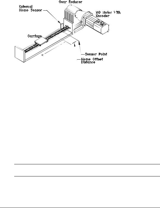
Figure 6: Basic Home Function, Example
The figure above show a basic home function using a ball screw. This example uses most of the setup features in the PowerTools Pro Home tab.
Home Sequence
1.Back off the sensor (if on the sensor. This step is optional).
2.Move to the external home sensor to establish a home reference point.
3.Next it will move to the Offset position.
4.Then the command and feedback positions are set to the value entered into the End of Home Position.
Homing to the motor’s encoder marker will establish the most accurate and repeatable home position. This method will position the motor relative to the location of the rising edge of the encoder marker pulse. Most applications will use a sensor and marker to find an accurate home position in the vicinity of the home sensor.
Several parameters affect how the Home function operates. Each of these parameters are explained in detail on the following pages.
Note
The Home function will NOT be initiated when any other motion command is in progress.
Establishing a Home Reference Position
The first step in setting up a home is to select the desired home reference type. The Home Reference parameter selected determines how the Home Reference Position is established.
9
FM-3 Programming Module Reference Manual
PowerTools Pro allows selection of one of three different Home References: Sensor, Marker, or Sensor and Marker.
Sensor
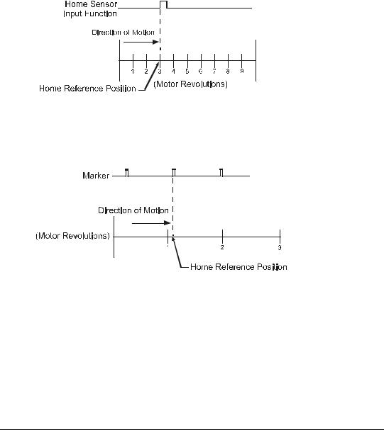
Selecting Sensor means the rising edge of the Home Sensor input function is used to establish the home reference position.
Figure 7: Sensor Home Reference Position
Marker
Selecting Marker means the rising edge of the motor’s encoder marker channel is used to establish the reference position.
Figure 8: Marker Home Reference Position
10
Operational Overview
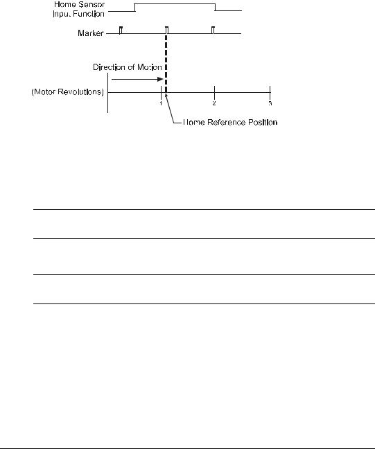
Sensor and Marker
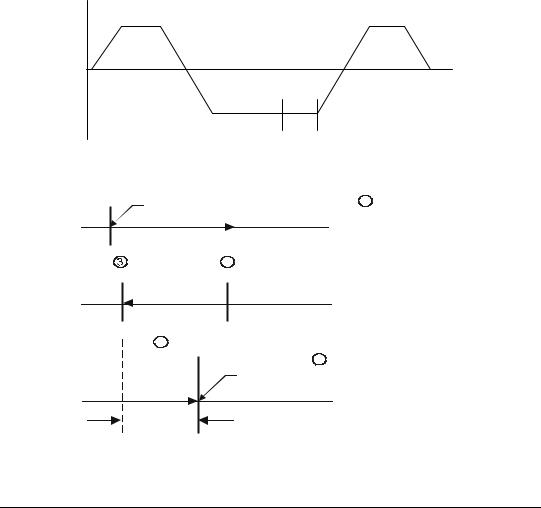
Selecting Sensor and Marker means the reference position is established using the first marker rising edge after the device sees the rising edge of the Home Sensor input function.
Figure 9: Sensor and Marker Home Reference Position Example 1
Accuracy and Repeatability
The amount of accuracy your application requires will determine the Home Reference option you select. Homing to an external sensor only will establish a repeatable home position within 0.04 revolutions at 3000 RPMs (800 sec sensor capture interval).
Note
The data above assumes the use of a perfectly repeatable home sensor.
In Sensor and Marker applications, the marker must be at least 800 sec after the rising edge of the sensor input to be considered a valid marker pulse.
Note
At 1000 RPM, the motor will travel 0.0133 revolutions (or 4.8°) in 800 sec.
11
FM-3 Programming Module Reference Manual
800 µsec
Sensor
Marker
Direction of Travel
Figure 10: Sensor and Marker Home Reference Position Example 2
The Home Sensor must be “On” for at least 800 sec to guarantee that it will be recognized.
Sensor Min.
On Time
Sensor
800 µsec
Figure 11: Sensor and Marker Home Reference Position Example 3
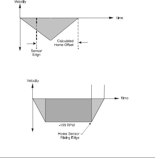
Home Offset
The Home Offset is the distance from the Reference Position to the final stopping point at the end of the homing sequence. Regardless of the value you enter for the Offset or which Home Reference you choose, there is always an offset inherent in the homing process.
The user may either specify a desired offset or allow the drive to calculate an offset automatically. The drive calculates an offset that guarantees that the motor will not have to backup to get to the offset position. This is very convenient for unidirectional applications.
The calculated offset is the distance travelled during deceleration ramp from the home velocity to a stop plus the distance travelled at the home velocity for 800 sec. This extra distance is used to guarantee that the motor will not need to backup after the deceleration ramp.
12
Operational Overview
The Specified Offset allows the user to choose an exact offset from the Home Reference.
Once the home reference is detected, the device will do whatever is necessary to reach the offset position. This may be as simple as a deceleration to a stop, a continuation at speed followed by a deceleration to a stop, or a deceleration followed by a move in the opposite direction.
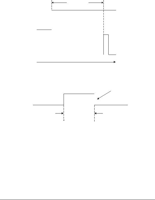
To enter a specified home offset, select the Specified Offset radio button. PowerTools Pro always displays the calculated offset value as a reference. If the home reference is detected before the axis has reached its peak velocity, the axis will still continue to the precise offset position.
Figure 12: Calculated Home Offset, Peak Velocity Not Reached
If the Home Reference is detected after the axis has reached its peak velocity, the axis will decelerate to the precise offset position.
Calculated
Home Offset
Figure 13: Calculated Home Offset, Peak Velocity Reached
13
FM-3 Programming Module Reference Manual
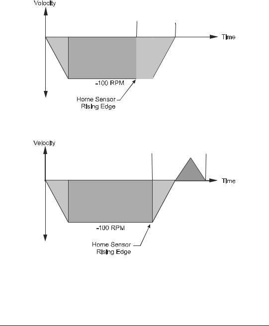
Two examples below show operation when the specified offset is greater or less than the calculated offset. This causes the axis to continue on at speed before decelerating and stopping at the offset position, or backing up after the home sensor.
Specified
Offset
Figure 14: Specified Home Offset, Greater than Calculated Offset
Specified
Offset
Figure 15: Specified Home Offset, Backup Required
End of Home Position
The End of Home Position (End Posn) defines the home position in relation to the machine’s coordinate system. At the completion of the home, the value of the End of Home Position is put into the command position.
14
Operational Overview
Home Limit Distance
This parameter places an upper limit on the incremental distance the motor will travel during the home.
If no reference is found, the system will decelerate and stop at the limit distance. The Home Limit Distance Hit function will be activated if the home stops at the limit distance without finding the reference. Additionally, the Home.CommandComplete function will not turn “On” if the limit distance is hit.
Home Examples
Example 1: Linear Application
In this example, the system uses an external sensor and the motor’s encoder marker channel to establish a Home Reference Position. This is the most accurate and most common way to home.
Figure 16: Home to Sensor and Marker, Example
When the FM-3 module sees the Home Initiate, it accelerates the motor to the Home Velocity.
The motor continues at that velocity until it first senses the Home Sensor input. It continues at the same velocity until the motor’s encoder marker channel is sensed. The rising edge of the motor’s encoder marker channel is used to establish the reference position. Once the home reference is detected, the motor decelerates to a stop and moves to the offset position.
15
FM-3 Programming Module Reference Manual
Home Sequence
1.If on sensor then back off (if enabled)
2.Search for sensor
3.Search for marker
4.Go to offset (2.0 Revs)
5.Set feedback position equal to End of Home Position
Velocity |
|
+ 100 |
+ 100 |
Back off |
|
Sensor |
|
|
Time |
- 100 |
|
Sensor |
Marker |
Figure 17: Home Velocity Profile
Start of Home |
1 |
|
|
||
|
|
Back Off Sensor |
|
|
2 |
Marker |
Sensor |
|
|
|
Home Move |
4 |
|
|
Offset Move |
|
5 |
|
|
|
2.0 Revs |
|
Final Position = End of Home Position |
|
|
|
Offset
Figure 18: Home Move Sequence
16
Loading...