


Operator’s
Manual
 7000 Series ADTS
Automatic Delayed–Transition Transfer Switches
E–design 150–400A, F–design 600–800A,
G–design 1000–4000A, F–design 3000–4000A,
TABLE OF CONTENTS section-page
INSTALLATION . . . . . . . . . . . . . . . . . . . . . . . . 1-1 Mounting and Line Connections . . . . . . . . . 1-1 Auxiliary Circuits and Harness . . . . . . . . . . . 1-2 Engine Starting Contacts . . . . . . . . . . . . . . . 1-2 Functional Test . . . . . . . . . . . . . 1-2, 1-3, 1-4, 1-5
TESTING & SERVICE . . . . . . . . . . . . . . . . . . 2-1 Transfer Test . . . . . . . . . . . . . . . . . . . . . . . . . . 2-1 Preventive Maintenance . . . . . . . . . . . . . . . . 2-1 Disconnecting the Controller . . . . . . . . . . . . 2-1 Manual Load Transfer . . . . . . . . . . . . . . . . . . 2-2 Trouble-Shooting . . . . . . . . . . . . . . . . . . . . . . 2-2
INDEX . . . . . . . . . . . . . . . . . . . . . . . . . back cover
Refer to the outline and wiring drawings provided with your 7000 Series ADTS for all installation and connection details and accessories.
DANGER is used in this manual to warn of high voltages capable of causing shock, burns, or death.
WARNING is used in this manual to warn of possible personal injury.
CAUTION is used in this manual to warn of possible equipment damage.
Refer to Group 5 Controller User’s Guide
381333–126 for ATS status display messages, time delays, pickup & dropout settings, and adjustments.
An experienced licensed electrician must install the ADTS.
G design 2000 A |
|
G design 4000 A |
50 Hanover Road, Florham Park, New Jersey 07932–1591 USA |
381333–129 C |
|
For sales or service call 1 800 800–2726 (ASCO) |
www.ascopower.com |
|
ASCO POWER TECHNOLOGIES CANADA PO Box 1238, 17 Airport Road, Brantford, Ontario, Canada N3T 5T3
Catalog Number Identification
Typical 7000 Series catalog no. for G–design switched neutral, 3 pole, 2000 A, 480 V, ADTS in Type 1 enclosure:
design |
G 7ADTS |
|
B |
3 |
2000 |
N |
5 |
|
C |
||||
|
|
|
|
|
|
|
|
|
|
|
|
|
|
prefix |
|
|
|
|
|
|
|
|
|
|
|||
letter |
|
|
|
|
|
|
|
|
|
|
|||
Neutral |
|
Phase Poles |
|
Amperes |
|
Voltage |
|
Controller |
||
A – solid |
|
2 – single Ø |
|
150 |
1000 |
|
A 115 |
J 400 |
|
5 – standard |
B – switched |
|
3 – three Ø |
|
260 |
1200 |
|
B 120 |
K 415 |
|
5X – if |
|
|
|
|
400 |
1600 |
|
C 208 |
L 440 |
|
accessories |
|
|
|
|
|
|
ordered |
||||
|
|
|
|
600 |
2000 |
|
D 220 |
M 460 |
|
|
blank – none |
|
|
|
|
|
|
||||
|
|
|
|
800 |
3000 |
|
E 230 |
N 480 |
|
|
|
|
|
|
|
4000 |
|
F 240 |
P 550 |
|
|
|
|
|
|
|
|
|
|
|||
|
|
|
|
|
|
|
G 277 |
Q 575 |
|
|
|
|
|
|
|
|
|
|
|
||
|
|
|
|
|
|
|
H 380 |
R 600 |
|
|
|
|
|
|
|
|
|
|
|
|
|
Enclosure
C – type 1
F – type 3R
G – type 4
L – type 12
M –type 3R secure
N –type 4 secure
P –type 4X secure
Q –type 12 secure blank – open type
field connections |
Group 5 |
|
terminal block TB |
||
Controller |
||
|
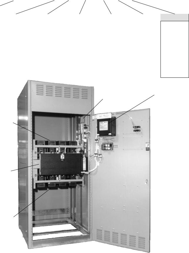
power
connections Transfer  Control & lights
Transfer
Switch
power connections
G–design 2000 ampere size in typical enclosure with location of customer connections
Rating Label
Each automatic delayed–transition transfer switch contains a rating label to define the loads and fault circuit withstand / closing ratings. Refer to the label on the transfer switch for specific values.
Do not exceed the values on the rating label. Exceeding the rating can cause personal injury or serious equipment damage.
Nameplate
The Transfer Switch nameplate includes data for each specific 7000 Series ADTS. Use the switch only within the limits shown on this nameplate. A typical Catalog Number is shown on the previous page with its elements explained.
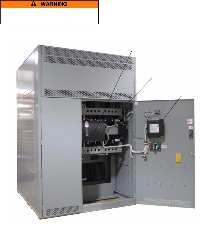
Transfer
Switch
field connections terminal block TB
Group 5
Controller
G–design 4000 ampere size in typical enclosure with location of customer connections
SECTION 1 INSTALLATION
ASCO Series 7000 Automatic Delayed–Transition Transfer Switches are factory wired and tested. Field installation simply requires mounting and connection of service cables, and auxiliary control circuits (if required).
Remove the Shipping Skid
For large switches, open the front door and remove the four lag screws (2 in front, 2 in rear) securing enclosure to the wood skid.
Supporting Foundation
The supporting foundation for the enclosure must level and straight. Refer to the applicable enclosure outline drawing included with the ADTS for all mounting details including door opening space.
If bottom cable entry is used, the foundation must be prepared so that the conduit stubs are located correctly. Refer to the enclosure outline drawing for specified area and location. Provide cable bending space and clearance to live metal parts. When a concrete floor is poured, use interlocking conduit spacer caps or a wood or metal template to maintain proper conduit alignment.
Mounting
Refer to the outline and mounting diagram provided with the ADTS; it shows all mounting details and instructions.
Protect the switch from construction grit and metal chips to prevent malfunction or shortened life of the automatic switch switch.
Mount the ADTS vertically to a rigid supporting structure. Level all mounting points by using flat washers behind the holes to avoid distortion of the switch.
The controller is mounted on the cabinet door. An add-on DIN rail is provided for some optional accessories and is mounted below controller on the door.
Auxiliary Cable Boxes
For 1000 & 1200 amp. sizes, an auxiliary cable box is required for all (normal, emergency, & load)bottom or top entry. Order ASCO part no. 609027 if required.
On 1000 & 1200 amp. be sure to install auxiliary cable box if both service and load cables are entering through the top or bottom of enclosure.
Line Connections
A Wiring Diagram is furnished with the ASCO Series 7000 ADTS (separate from this manual). Refer to this drawing. All wiring must be made in accordance with the National Electrical Code and local codes.
De–energize the conductors before making any line or auxiliary circuitry connections. Be sure that Normal and Emergency line connections are in proper phase rotation. Place engine generator starting control in the OFF position. Make sure engine generator is not in operation.
Testing Power Conductors
Do not connect the power conductors to the transfer switch until they are tested. Installing power cables in conduit, cable troughs and ceiling-suspended hangers often requires considerable force. The pulling of cables can damage insulation and stretch or break the conductor’s strands. For this reason, after the cables are pulled into position, and before they are connected, they should be tested to verify that they are not defective or have been damaged during installation.
Connecting Power Conductors
After the power cables have been tested, connect them to the appropriate terminal lugs on the transfer switch as shown on the wiring diagram provided with the switch. Make sure the lugs provided are suitable for use with the cables being installed. Standard terminal lugs are solderless screw type and will accept the wire sizes listed on the drawings provided with the switch. Be careful when stripping insulation from the cables; avoid nicking or ringing the conductor. Remove surface oxides from cables by cleaning with a wire brush. When aluminum cable is used, apply joint compound to conductors. Tighten cable lugs to the torque specified on rating label.
Do not run cables in front of or behind the switch. Cables can be bundled on the right side of the switch. Maintain proper electrical clearance between the live metal parts and grounded metal: ½ inch minimum for 150-400 amps, 1 inch minimum over 400 amps.
It is not necessary to remove the barriers from the transfer switches to install the cables. If you do remove them,however, be sure to reinstall the barriers carefully.
Bus Connections
For large switches use grade 5 hardware to connect bus to appropriate terminal plates. Wipe off the bus surfaces before they are joined. If the bus is very dirty, gently clean the surfaces with a non---flammable solvent. Avoid touching the cleaned surfaces.
Do not breathe cleaning solvent vapors.
1--1
 Loading...