


READ AND SAVE THESE INSTRUCTIONS
PRIMA SNUGGER
Ceiling Fan Owner's Manual
Model Numbers
CF905BS00 CF905ORB00 CF905CK00 CF905VNB00 CF905GES00
Net Weight: 18.3 Lbs.
Part No. F40BP74320000 |
Form No. BP7432 |
|
U.L. Model No.: CF905 |
!WARNING
WARNING: To avoid fire, shock, and serious personal injury, follow these instructions.
Safety Instructions
1.Read your owner’s manual carefully and keep it for future reference.
2.Before servicing or cleaning unit, switch power off at service panel and lock service panel disconnecting means to prevent power from being switched on accidentally. When the service disconnecting means cannot be locked, securely fasten a warning device, such as a tag, to the service panel.
3.Be careful of the fan and blades when cleaning, painting, or working near the fan. Always turn off the power to the ceiling fan before servicing.
4.Do not put anything into the fan blades while they are turning.
5.Do not operate reversing switch until fan blades have come to a complete stop.
Additional Safety Instructions for Installation
1.To avoid possible shock, be sure electricity is turned off at the fuse box before wiring, and do not operate fan without blades.
2.All wiring must be in accordance with the National Electrical Codes “ANSI/NFPA 70-2008” and Local Electrical Codes. Use the National Electrical Code if Local Codes do not exist. The ceiling fan must be grounded as a precaution against possible electrical shock. Electrical installation should be made or approved by a licensed electrician.
3.The ceiling structure must be capable of reliably supporting at least 50 pounds.
4.Use only U.L. outlet boxes listed as “Acceptable for Fan Support”, and use the mounting screws provided with the outlet box. Most outlet boxes commonly used for support of light fixtures are not acceptable for fan support and may need to be replaced. Consult a qualified electrician if in doubt.
5.The fan must be mounted with the fan blades at least 7 feet from the floor to prevent accidental contact with the fan blades.
6.Follow the recommended instructions for the proper method of wiring your ceiling fan. If you do not know enough about electrical wiring, have your fan installed by a licensed electrician.
NOTE: All set screws must be checked and re-tightened where necessary before installation.
NOTE: This fan is suitable for use with solid-state speed controls.
WARNING: To reduce the risk of fire or electric shock, this fan should only be used with fan speed control, Model No. SW46/U.L. Model No. UC9020 manufactured by Rhine Electric Co., Ltd.
WARNING: To avoid fire, shock or injury, do not use an Emerson or any other brand of control not specifically approved for this fan.
WARNING: This product is designed to use only those parts supplied with this product and/or any accessories designated specifically for use with this product by Emerson Electric Co. Substitution of parts or accessories not designated for use with this product by Emerson Electric Co. could result in personal injury or property damage.
WARNING: To reduce the risk of personal injury, do not bend the blade flange when installing the blade flanges, balancing the blades or cleaning the fan. Do not insert foreign objects in between rotating fan blades.
DATE CODE:
The date code of this fan may be found on the box, stamped in ink on a white label. You should record this data above and keep it in a safe place for future use.
2 |
U.L. Model No.: CF905 |
EMERSON QUICK START GUIDE
The Quick Start Guide covers the installation instructions common for ceiling fan operations. If additional assistance with wiring, alternate hanging systems, or lighting options, proceed to the complete instructions of this Owner’s Manual.
The Quick Start Guide sections include page numbers to correspond with the appropriate sections of the Owner’s Manual for detailed instructions.
*See Unpacking Instructions for a complete list of parts for installation.
!WARNING
To reduce the risk of fire, electric shock, or personal injury, mount fan to outlet box marked “Acceptable for Fan Support of 15.9 kg (35 lbs) or less", and use screws supplied with outlet box. Most outlet boxes commonly used for support of light fixtures are not acceptable for fan support and may need to be replaced. Consult a qualified electrician if in doubt.
How to Wire Your Ceiling Fan (page 8)
!WARNING
Turning off wall switch is not sufficient. To avoid possible electrical shock, be sure electricity is turned off at the main fuse or circuit breaker box before wiring. All wiring must be in accordance with National and Local codes and the ceiling fan must be properly grounded as a precaution against possible electrical shock.
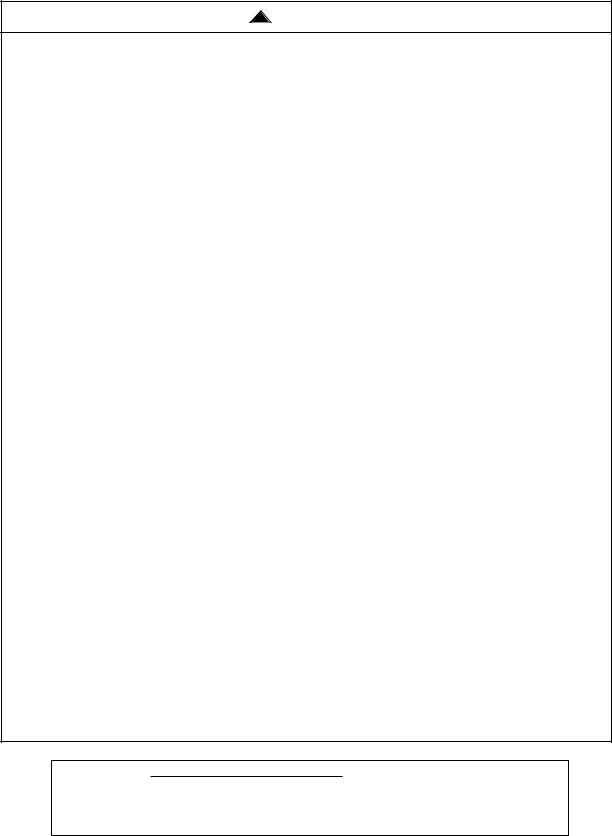
1.Disconnect electrical power to the branch circuit at the circuit breaker or fuse box before attempting to install the ceiling fan hanger bracket on the outlet box.
2.Carefully pull the branch circuit wires though the center hole of the mounting plate.
OUTLET
BOX
CEILING
MOUNTING
PLATE
CEILING
MOUNTING
OUTLET BOX PLATE HOOK
SCREWS (2)
3.Attach ceiling mounting plate to outlet box using screws supplied with box.
4.Hang the fan motor assembly onto the ceiling mounting plate hook using the radial slot nearest the circular hole.
CEILING |
HOOK |
|
RADIAL SLOT |
||
MOUNTING PLATE |
||
|
HOLE |
5.Connect the green grounding lead from the mounting plate and the green grounding lead from the motor assembly to the supply grounding conductor (this may be a bare wire or wire with green colored insulation). Securely connect wires with wire connectors supplied.
6.Securely connect the fan motor white wire to the supply white (neutral) wire using wire connector supplied.
7.Securely connect the fan motor black wire to the supply black (hot) wire using wire connector supplied.
8.Cap the blue fan wire with a wire connector if using the supplied wall control.
9.After connections have been made, turn leads upward and carefully push leads into the outlet box, with the white and green leads on one side of the outlet box and the black and blue leads on the other side of the outlet box.
FAN MOTOR
BLUE WIRE
SUPPLY
BLACK WIRE
FAN MOTOR
BLACK WIRE
FAN MOTOR
WHITE WIRE
SUPPLY
WHITE WIRE
SUPPLY
GREEN WIRE
FAN MOTOR ASSEMBLY
FAN MOTOR ASSEMBLY
3 |
U.L. Model No.: CF905 |
EMERSON QUICK START GUIDE
How to Put Your Ceiling Fan Together (pages 9 & 10)
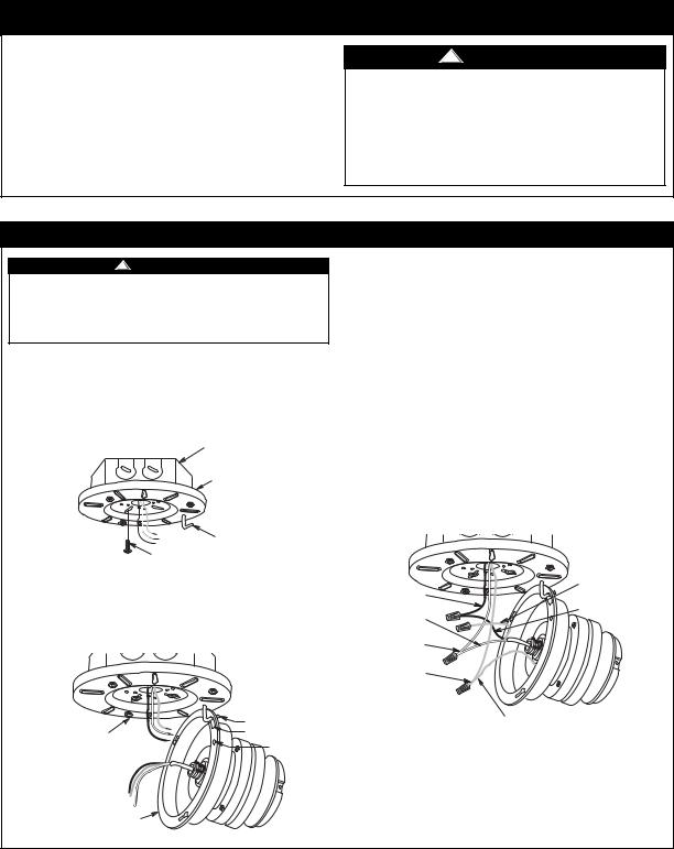
1.Remove the 10-24 x 3/8” pan head screw with lockwasher nearest the hook from the ceiling mounting plate and retain for later use. Loosen the remaining two 10-24 x 3/8” pan head screws several turns.
2.While still attached to the mounting plate hook, pivot the fan motor assembly upwards and mate it up against the ceiling mounting plate. Align and engage the two keyhole slots with the two loosened screw heads.
3.Securely tighten both 10-24 x 3/8” pan head screws.
4.Reinstall the previously removed 10-24 x 3/8” pan head screw with lock washer to lock the motor assembly onto the ceiling mounting plate.
5.Loosen two opposing 10-24 x 3/8” pan head screws and remove the remaining two 10-24 x 3/8” pan head screws from the outer rim of the ceiling mounting plate.
6.Slide the fan housing trim ring over the fan housing cover.
7.Position the fan housing cover over the fan motor assembly, align and rotate the housing to engage the two loosened 10-24
x3/8” pan head screw heads in the ceiling mounting plate. Securely tighten both screws.
8.Reinstall the previously removed 10-24 x 3/8” pan head screws to lock the housing cover onto the ceiling mounting plate.
9.Push the trim ring upwards and rotate so that it engages and locks onto the four mounting screw heads of the fan housing cover.
10.Mount the blade flanges to the fan blades using three 10-24 x 5/16” washer head blade screws per blade (supplied). Repeat for the four remaining blades.
KEY HOLE SLOT
 10-24 x 3/8" PAN
HEAD SCREW WITH
LOCKWASHER (3)
FAN MOTOR
ASSEMBLY
TIGHTEN TWO OPPOSING 10-24 x 3/8"
PAN HEAD SCREWS
 FAN CEILING
MOUNTING PLATE
REINSTALL THE TWO PREVIOUSLY REMOVED 10-24 x 3/8" PAN HEAD SCREWS
 FAN HOUSING
COVER
MOUNTING
SCREW HEADS
 CEILING
TRIM RING
 FAN
FAN
HOUSING
COVER
10-24 x 5/16" WASHER  HEAD BLADE SCREW (3)
FAN BLADE BLADE FLANGE 

4 |
U.L. Model No.: CF905 |

EMERSON QUICK START GUIDE
How to Put Your Ceiling Fan Together (pages 10 & 11)
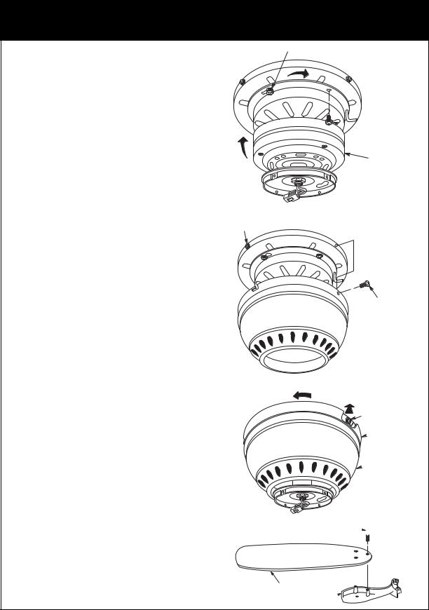
11.Attach one blade assembly to the motor using the two 1/4-20 x 9/16” captive flange screws with lockwashers. Make sure the screws are tightened securely. Repeat this procedure for the other four blade assemblies.
NOTE: Take care not to scratch the fan housing when installing the blade assemblies.
12.Remove the four switch housing assembly mounting screws from the switch housing plate and retain for future use.
13.Engage the connector of the switch housing assembly with the fan motor assembly connector. The two connectors are keyed and color-coded and must be mated correctly (color-to-color) before they can be engaged. Make sure the connector latch closes properly.
BLADE FLANGE ASSEMBLY
1/4-20 x 9/16" CAPTIVE FLANGE SCREW WITH LOCKWASHER (2 sets per flange)
SWITCH HOUSING MOUNTING PLATE HOLE
14.Position the switch housing assembly on the switch housing plate and align the holes in the switch housing assembly with the holes in the plate. Secure the switch housing assembly by installing the four screws removed previously.
NOTE: To install an accessory light kit, remove switch housing and make light kit electrical connections to blue and white leads marked “For Light” in the switch housing. Follow light kit instructions for wiring and installation. Then reinstall switch housing as outlined above.
See page 10 for detailed instruction of how to connect the blue fan wire to the branch circuit.
SWITCH HOUSING
CONNECTOR
MOTOR CONNECTOR
SWITCH HOUSING
MOUNTING SCREW (4)
SWITCH
HOUSING
ASSEMBLY
MOUNTING
SCREWS (4)
Installation of Wall Control (page 12)
!WARNING
Turning off wall switch is not sufficient. To avoid possible electrical shock, be sure electricity is turned off at the main fuse or circuit breaker box before wiring. All wiring must be in accordance with National and Local codes and the ceiling fan must be properly grounded as a precaution against possible electrical shock.
NOTE: Electric connections should be in accordance with the National Electrical Codes and all Local Codes. Before starting, disconnect power to the circuit at the fuse box or circuit breaker panel.
1.Remove the faceplate and screws from the existing wall switch. Pull switch out from wall outlet box.
2.Disconnect wire from existing fan wall switch.
3.Slide the fan control in the OFF position (0).
4.Connect one BLACK wire from the fan control to the fan/motor lead with a wire connector (provided).
5.Connect the other BLACK wire from the fan control to the 120VAC hot wire with a wire connector (provided).
NOTE: Use wire connectors (supplied) to secure electrical connections.
6.Attach the fan control to the wall outlet box with two 6-32 x 3/4” screws (provided).
7.Position the faceplate (provided) onto the speed control. Using the two 6-32 x 1/4” screws, screw the faceplate and speed control to the wall outlet box.
TO
NEUTRAL
TO FAN MOTOR LOAD
MOTOR LOAD
1.2 AMP MAXIMUM
BLACK 
3 |
BLACK |
4 |
|
2 |
|
1 |
|
0 |
|
TO 120VAC
SOURCE HOT
* For additional installation review full instructions on page 12.
5 |
U.L. Model No.: CF905 |
 Loading...