


Operator’s
Manual
 7000 Series 7ATB
Automatic Transfer &
Bypass–Isolation Switches
G design 1000 through 4000 amp. sizes
DANGER is used in this manual to warn of high voltages capable of causing shock, burns, or death.
WARNING is used in this manual to warn of possible personal injury.
CAUTION is used in this manual to warn of possible equipment damage.
Refer to the outline and wiring drawings provided with your 7000 Series ATB for all installation and connection details and accessories.
Refer to Group 5 Controller User’s Guide 381333–126 for ATS status display messages, time delays, pickup & dropout settings, and adjustments.
An experienced licensed electrician must install the 7ATB.
Rating Label
Each 7000 Series 7ATB contains a rating label to define the loads and fault circuit withstand/closing ratings. Refer to the label on the Transfer Switch for specific values.
Do not exceed the values on the rating label. Exceeding the rating can cause personal injury or serious equipment damage.
Nameplate
The Transfer Switch nameplate includes data for each specific 7000 Series ATB. Use the switch only within the limits shown on this nameplate. A typical Catalog Number is shown below with its elements explained:
TABLE OF CONTENTS section-page
INSTALLATION
Mounting . . . . . . . . . . . . . . . . . . . . . . . . . . . . . 1-1 Power Connections . . . . . . . . . . . . . . . . . . . . 1-2 Engine Starting & Auxiliary Circuits . . . . . . 1-2 Functional Test . . . . . . . . . . . . . . . . . . . . . 1-3, 1-4
TESTING & SERVICE
Transfer Test . . . . . . . . . . . . . . . . . . . . . . . . . . 2-1 Preventive Maintenance . . . . . . . . . . . . . . . . 2-1 Disconnecting the Controller . . . . . . . . . . . . 2-1 Manual Load Transfer . . . . . . . . . . . . . . . . . . 2-2 Trouble-Shooting . . . . . . . . . . . . . . . . . . . . . . 2-2
BYPASSING & ISOLATING
Bypassing the ATS . . . . . . . . . . . . . . . . . . . . 3-1 Isolating the ATS . . . . . . . . . . . . . . . . . . . . . . 3-2 Return to Service . . . . . . . . . . . . . . . . . . . 3-3, 3-4
4000 amp. size |
INDEX |
back cover |
|
||
50 Hanover Road, Florham Park, New Jersey 07932–1591 USA |
381333–132 F |
|
For sales or service call 1 800 800–2726 (ASCO) www.ascopower.com |
|
|
ASCO POWER TECHNOLOGIES CANADA PO Box 1238, 17 Airport Road, Brantford, Ontario, Canada N3T 5T3
Catalog Number Identification |
|
Typical 7000 Series ATB catalog no. for overlapping |
|||||||||||
|
|
|
|
|
|
|
neutral, 3 pole, 4000 amp., 480 V, in Type 1 enclosure: |
||||||
|
G7ATB |
|
C |
|
3 |
4000 |
|
N |
|
5 |
|
C |
|
Neutral |
|
Phase Poles |
|
Amperes |
|
A – solid |
|
2 |
– single Ø |
|
1000 |
B – switching |
|
3 |
– three Ø |
|
1200 |
C – overlapping |
|
|
|
|
1600 |
blank – none |
|
|
|
|
2000 |
|
|
|
|
|
2600 |
|
|
|
|
|
3000 |
|
|
|
|
|
4000 |
|
|
|
|
|
|
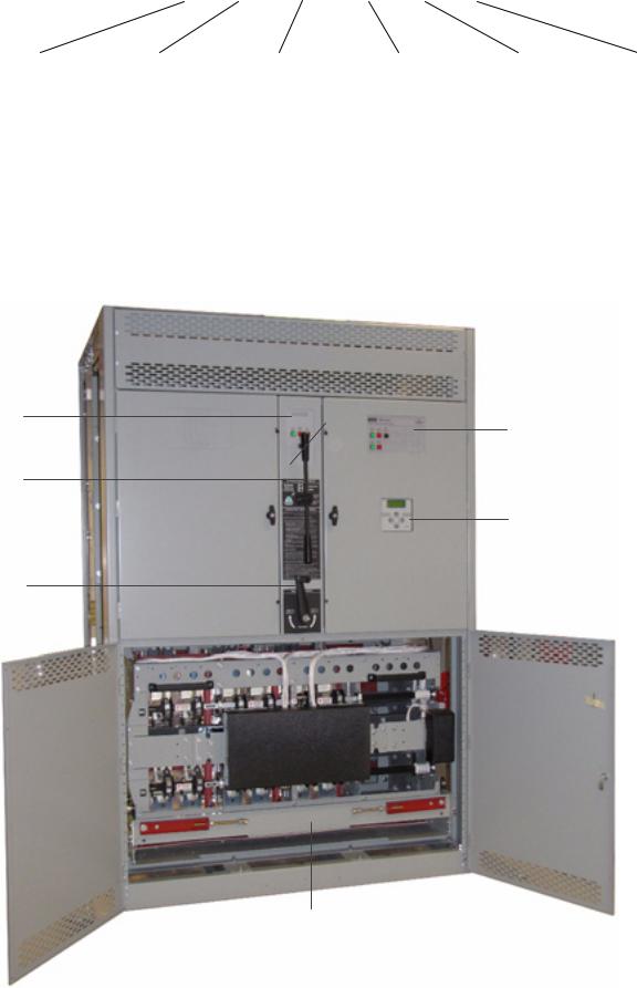
Status
Lights
&
Engine
Control
Bypass
Handle
Isolation
Handle
Voltage |
|
Controller |
|
Enclosure |
|
A 115 |
J 400 |
|
5 – standard |
|
C – type 1 |
B 120 |
K 415 |
|
5X – if |
|
F – type 3R |
C 208 |
L 440 |
|
accessories |
|
G – type 4 |
|
ordered |
|
|||
D 220 |
M 460 |
|
|
L – type 12 |
|
|
|
|
|||
E 230 |
N 480 |
|
|
|
blank – open type |
F 240 |
P 550 |
|
|
|
|
|
|
|
|
||
G 277 |
Q 575 |
|
|
|
|
H 380 |
R 600 |
|
|
|
|
|
|
|
|
|
|
Transfer Control
& Lights
Group 5 Controller
Transfer Switch
G7ATB 4000 A with the lower doors open (transfer switch shown)
SECTION 1 INSTALLATION
The ASCO 7000 Series Automatic Transfer & Bypass–Isolation Switch (ATB) consists of an upper bypass–isolation switch, a lower transfer switch, a monitoring and transfer controller, and door–mounted controls. The ATB is factory wired and tested. Installation requires removal of the shipping skid then securing the enclosure to the supporting foundation.
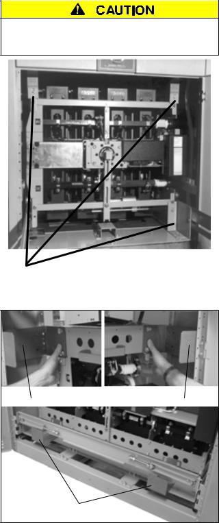
Remove Shipping Brackets / Angles from the Transfer Switch
Open the lower front door(s). The Transfer Switch carriage is secured to the frame for shipment. Remove the three or four shipping brackets or L–angles (1 upper left, 1 upper right, 1 lower right, or 2 lower on 4000 A).
Remove the Shipping Skid
Open the front lower door and remove the two front lag screws securing the enclosure to the wood skid. Next remove the rear lower panel and remove the two rear lag screws securing the enclosure to the wood skid.
To prevent serious damage, remove 3 shipping angles from the transfer switch carriage. Do not turn the Isolation Handle until they are removed!
Supporting Foundation
The supporting foundation for the enclosure must be level and straight. Allow at least 35 inches in front of the enclosure for draw out of the Transfer Switch.
Refer to the enclosure outline drawing included with the ATB for all mounting details including door opening space.
If bottom cable entry is used, the foundation must be prepared so that the conduit stubs are located correctly. Refer to the appropriate enclosure outline drawing for specified cable entrance area and location. Provide cable bending space and clearance to live metal parts. When a concrete floor is poured, use interlocking conduit spacer caps or a wood or metal template to maintain proper conduit alignment.
Mounting
Refer to the enclosure outline drawing furnished with this switch and mount the 7000 Series ATB according to the details and instructions shown on the drawing.
1---1
remove 3 or 4 shipping brackets ( L–angles)
Figure 1-1. On 1000–3000 A remove three shipping L–angles.
remove 2 upper shipping brackets
remove 2 lower shipping brackets
Figure 1-2. 4000 A remove four shipping L–angles.
 Loading...