


7400
Single Phase UPS system
S i n g l e m o d u l e a n d ‘1 + N’ ( e x p a n d a b l e )
UNINTERRUPTIBLE POWER SYSTEM
U s e r M a n u a l
EMERSON Network Power (India) Pvt. Ltd.

Dear Customer,
Please accept our thanks for giving us the privilege to serve you by choosing a Liebert
make ‘UPS’.
If this is your first Liebert UPS, we hope it is the beginning of a long relationship
which delivers value to your organisation. If you already own and use a Liebert, we are
doubly honoured by your decision of continuing this relationship.
It is our constant endeavour to partner you for the growth and success of your business.
This philosophy is reflected in our Mission statement “To deliver value through Air
& Power Quality solutions to achieve customer delight”. Please do give us
feedback to help us realize our Mission.
Emerson Network Power (India) Private Limited

IMPORTANT
This manual contains information concerning the installation, operation and maintenance
of the Series 7400 1Phase Uninterruptible Power System (UPS) for the single module
and one plus one Systems.
All relevant parts of the manual should be read prior to commencing installation.
The UPS must be commissioned by an engineer approved by the manufacturer (or his
agent) before being put into service. Failure to observe this condition will invalidate any
implied warranty.
The Series 7400 1Phase UPS has been designed for Commercial / Industrial use only.
The Series 7400 1Phase UPS is not designed for direct use in any life support
application.
If you encounter any problem with the procedures contained in this manual you should
seek immediate assistance from Emerson Network Power (India) Pvt. Ltd. Sales Office
from whom the equipment was purchased. Alternatively contact the Emerson Network
Power (India) Pvt. Ltd. Customer Service & Support department at the address shown
below:
EMERSON NETWORK POWER
(INDIA) PRIVATE LIMITED
Plot No. C-20, Road No. 19
Wagle Industrial Estate
Thane – 400 604, INDIA
Phone : +91 22 5807000
5802388
Fax : +91 22 5800829
5828358
Emerson Network Power (India) Pvt. Ltd. pursues a policy of continual product development and
reserves the right to change the equipment without notice.
@ Copyright 2001 by Emerson Network Power (India) Pvt. Ltd.
Unauthorized reproduction prohibited
All rights reserved

REGISTERED AND HEAD OFFICEREGISTERED AND HEAD OFFICE
EMERSON NETWORK POWER (INDIA) PVT. LTD.
PLOT NO. C-20, ROAD NO. 19
WAGLE INDUSTRIAL ESTATE
THANE – 400 604 MAHARASHTRA ,INDIA
TELEPHONE: (00 91 22) 5807000 / 5802388
FAX: (00 91 22) 5800829 / 5828358
Z O N A L O F F I C E S
MUMBAI
B 414-424, Bhaveshwar Arcade,
(opp. Shreyas cinema), LBS Road,
Ghatkopar(W), MUMBAI – 400 086
Tel : 022-5002318, 5002294, 5002437
Fax: 022-5002415 Pager : 9623-988 000
Mobile : 9820030917, 9820030915
NEW DELHI
18 / 14, WEA, Pusa Lane, Karol Baug;
NEW DELHI 110 005
Tel : 011- 5724706, 5781878, 5781071,
5744774, 5766438
Fax: 011- 5757601
Pager : 9632-100 300
KOLKOTA
77 A, Raja Basant Roy Road,
KOLKOTA – 700 029
Tel : 033 - 4646387, 4647197
Fax: 033 – 4667172
BANGALORE
501, C Wing, Mittal Towers,
No.6, MG Road, BANGALORE – 560 001
Tel : (080) – 55994543, 5598825, 5581448
Pager: (080) 96239888000
Fax: 080 – 558 8546

Branch Offices:
BARODA
39 / 2, Arunodaya Society,
Alkapuri, BARODA -390 005
Tel : 0265-314296, 330383
Fax: 0265-314296, 330383
CHANDIGARH
SCO-198 / 199 / 200,
Sector – 34A, Near Labour Chowk,
CHANDIGARH
Phone: 0172-662 873
Mobile: 9814100901
CHENNAI
No. 22, First Floor, Gopal Krishna Road,
T. Nagar, CHENNAI – 600 017
Tel : 044 - 8231742, 8221063, 8228996
Fax: 044 - 8231742
COCHIN
Lakshmini No. 36 / 2684,
Veluthamma House, Azad Road,
Kaloor, COCHIN 682017
Tel : 0484 - 341985
Fax: 0484 - 341986
GOA
622 / A, La Citadel Colony
Dona Paula, GOA – 403 004
Tel : c/o. 0832 – 220 723
JAMSHEDPUR
Kashi kunj, Road no. 2, Gr. Floor
Contractor’s area, Bistupur;
JAMSHEDPUR – 831 001
Tel : 0657-437549
Fax: 0657-437549
LUCKNOW
206, Sriram Tower, Ashok Marg
LUCKNOW
Phone : 0522-201467
Pager : 9628-555091
Mobile: 9839025563
NAGPUR
203, Ganga Apts,
13, Giripeth
NAGPUR 400 010
Phone / Fax : 0712 – 540423, 548551
PUNE
B-6, Shri Dwarka co -op. Society,
467/ C1, Hare Krishna Mandir Path,
Model Colony, Off University Road,
PUNE – 411006
Tel : 020 - 5676975, 5670709
Fax: 020 - 4004020
SECUNDARABAD
Plot no. 4, Sardar Patel Road
SECUNDARABAD – 500 003
Tel : 040 - 7717263, 7719196
Fax: 040 - 7806502
GUWAHATI
South Savania, Ashram Road,
Ulubari, GUWAHATI 781 007
Tel : 0361 - 543848
Fax: 0361 - 543270
Mobile: 9864023587

Safety Procedure
WARNING
This is a class A UPS product. In a domestic environment, this
product may cause radio interface in which case the user may
be required to take additional measures.
WARNING
HIGH EARTH LEAKAGE CURRENT: EARTH CONNECTIONS IS
ESSENTIAL BEFORE CONNECTING THE INPUT SUPPLY.
This equipment must be earthed in accordance with local
electrical codes.
WARNING
THIS UPS DOES NOT INCORPORATE AUTOMATIC BACKFEED
PROTECTION. A WARNING LABEL MUST BE FITTED TO ALL
EXTERNAL PRIMARY POWER ISOLATIONS STATING.
INSULATE THE UNINTERRUPTIBLE POWER SYSTEM BEFORE
WORKING ON THIS CIRCUIT.

GENERAL
As with other types of high power equipment, dangerous voltages are present within
the UPS and battery enclosure. The risk of contact with these is minimised as the live
component parts are housed behind a hinged, lockable door. Further internal safety
screens make the equipment protected to IP20 standards.
No risk exists to any personnel when operating the equipment in the normal manner,
following the recommended operating procedures.
All equipment maintenance and servicing procedures involve internal access and
should be carried out only by trained personnel.
BATTERIES
Battery manufacturers supply details of the necessary precautions to be observed
when working on, or in the vicinity of a large bank of battery cells. These
precautions should be followed implicitly at all times.
Particular attention should be paid to the recommendations concerning local
environmental conditions and the provision of protective clothing, first-aid and fire
fighting facilities
TEST EQUIPMENT
When the battery is under charge, it is earth-referenced about its mid -point –e.g. if
the battery s being charged at 460V the battery extremities will be at +230V and –
230V with respect to neutral (earth). When using mains -powered test equipment
such as oscilloscopes in the UPS voltage area, always use a differential mode of
operation to disconnect the oscilloscope frame earth.
PERSONNEL
When working inside the UPS (trained personnel only) it is recommended that protection
be worn to prevent eye damage, should an electric ware be struck by mishandling or severe
electrical fault.
Some of the power components are very heavy. If their removal is necessary, ensure that
sufficient manpower is available; otherwise use adequate mechanical handling equipment.
When working in the gene ral area of the UPS where high voltages are present, a second
person should be standing -by to assist and summon help in case of accident.

I N D E X
1 General Description 1
1.1 Introduction 1
1.2 Design Concept 1
1.2.1 Redundant vs Non redundant configuration 1
1.2.2 7400 Module Design 2
1.2.3 Bypass Supplies 3
1.2.4 UPS Power Switch Configuration 4
1.2.5 Battery circuit breaker 4
1.2.6 One plus one parallel control 7
1.2.7 Common Battery 9
1.2.8 Operator Control Panel 10
1.2.9 Battery Circuit Breaker 13
1.2.10 Battery cabinet/ rack 13
1.3 Safety Precautions 14
1.3.1 General 14
1.3.2 Batteries 14
1.3.3 Test Equipment 14
1.3.4 Personnel 14
2 Operating Instructions 15
2.1 Introduction 15
2.1.1 Redundant Module System 15
2.1.2 Non Redundant Module System 15
2.1.3 General Notes 15
3 Installation (Electrical) 21
3.1 Introduction 21
3.1.1 Equipment Positioning and Environmental considerations 22
3.1.2 Raised floor installation 22
3.1.3 Battery Location 23
3.2 Preliminary Checks 23
3.3 Connecting UPS Power Cables 25
3.3.1 Cable entry 25
3.3.2 Cable rating 25
3.3.3 Cable connections 26
3.3.4 Cabling procedure 26
3.4 Battery Circuit Breaker Boxes 32

4 Optional Equipment 35
4.1 AS400 Interface Board (#10021512003) 36
4.1.1 AS400 Interface board outputs 36
4.1.2 Remote control inputs 36
4.1.3 Calibration 36
4.2 4-Way AS400 Interface Board (#100201120004) 38
4.2.1 Remote control inputs 38
4.2.2 Calibration 38
4.3 Output Interface (Remote alarms) Board (#100215120007 &
#100215120002) 40
4.3.1 Alarm Outputs 40
4.3.2 Remote control inputs 40
4.4 Remote Alarm Monitor (RAM) for Single Module and 1+1 UPS System
42
5 Maintenance 47
5.1 Introduction 47
5.2 Safety Precautions 47
5.3 Scheduled Maintenance 47
5.3.1 Daily checks 47
5.3.2 Weekly checks 48
5.3.3 Annual Service 48
5.3.4 Extended Service 49
5.3.5 Battery Maintenance 49
6 Troubleshooting 51
6.1 Troubleshooting UPS systems 51
6.1.1 Operating parameters and limitation s 51
6.1.2 General troubleshooting procedure 51
6.2 Display Panel Message Interpretation 55
ANNEXURE 57

Series 7400 Single Phase 1+N U PS
1.2.1 Redundant vs
Chapter 1Chapter 1
General Description
1.1 Introduction
The Uninterruptible Power Supply system is connected between a
critical load, such as digital drives & automation, distributed digital
Process Control System, telecom equipment, programmable logic
controller, mission critical applications, computer, and its three
phase mains power supply. Being designed to furnish a well
regulated 1 PH output power supply under all rated load and input
supply conditions the system offers the users the following
advantages: -
Increased power quality :
The UPS has its own internal voltage and frequency regulator
circuits which ensure that its output is maintained within close
tolerances independent of voltage and frequency variations on the
mains power lines.
Increased noise rejection :
By rectifying the input AC power to DC power, and then converting
it back to AC, any electrical noise present on the input mains
supply line is effectively isolated from the UPS output, therefore the
critical load sees only clean power.
Power blackout protection:
If the mains power fails, the UPS continues to power the critical
load from its battery source, leaving the load immune from power
disturbances.
1.2 Design Concepts
The one-plus-one system comprises two standard 7400 series UPS
Non-Redundant
configuration
modules which are modified to allow their outputs to be connected
in parallel. These can then be used in a “redundant” or “nonredundant” configuration as explained below.
In a non-redundant module configuration, the system is sized such
that both UPS modules are required to feed the potential load, and
if one of the two modules develops a fault, or is for some reason
shut down, the other module automatically shuts down also.
Note: In such an event the load is transferred to an unprocessed bypass supply as described later.
In a redundant module configuration the system is sized such that
the potential load can be provided by just one of the two modules.
Under normal circumstances both modules are operational and
share the load current equally; but if one module develops a fault,
or is shut down, the second module is able to take over the full load
demand and continue to provide it with processed, backed-up
power. The advantages of a redundant system over a nonredundant system in terms of overall system reliability are selfevident.
Changing a one-plus-one system’s configuration between
redundant and non-redundant is quite straightforward, being
carried out by configuration links on the circuit board, which
governs the modules’ parallel control operation.
1
Series 7400 Single Phase 1+N U PS
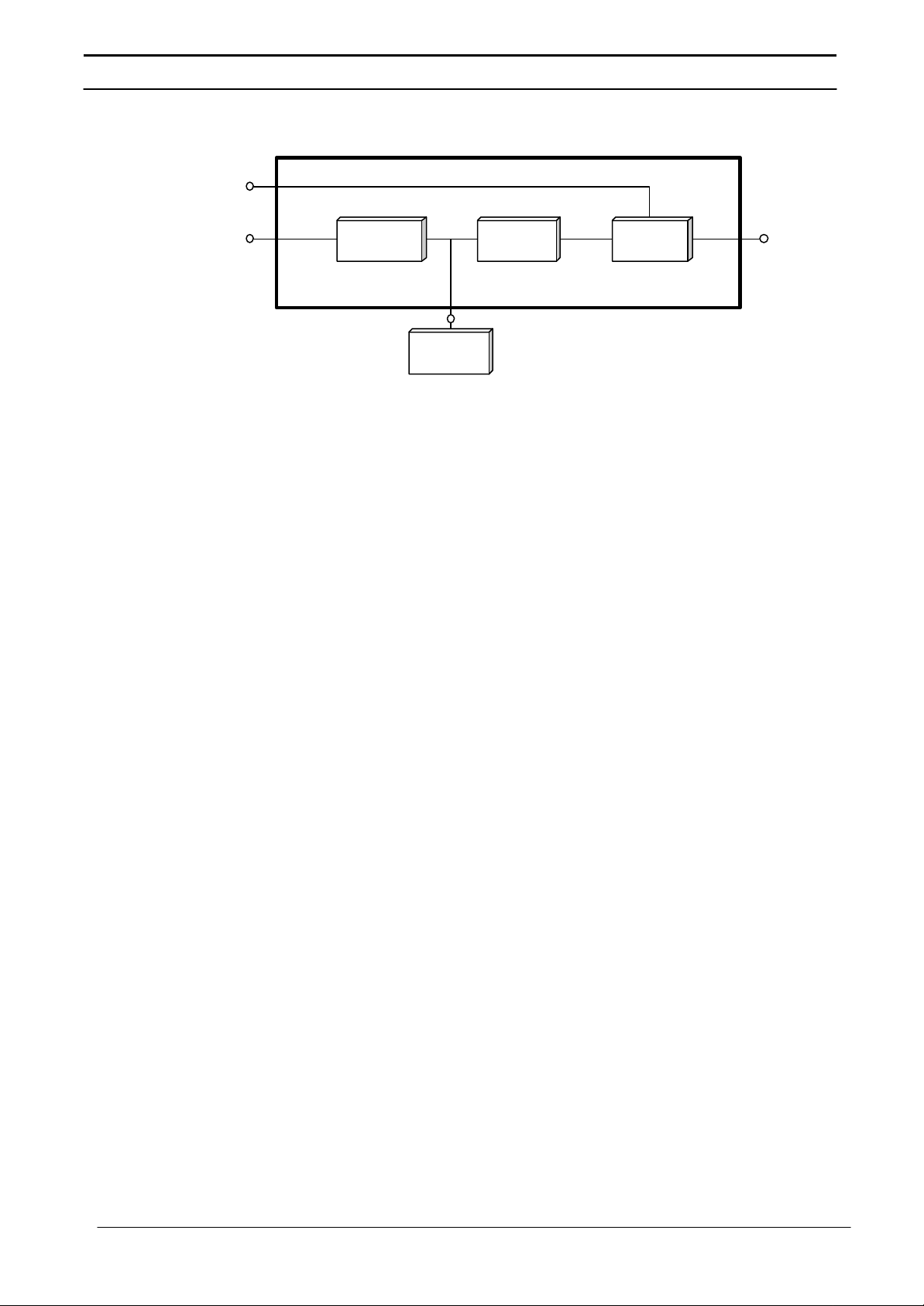
Figure 1: Series 7400 UPS Single Module Block Diagram
1.2.2 7400 Module
Design
Bypass
Supply
Mains
Supply
(a.c) (d.c) (a.c)
RECTIFIER
INVERTER
(d.c)
STATIC
SWITCH
UPS
Output
Supply
BATTERY
As previously mentioned, each of the two modules forming the
one-plus-one system is basically a standard single module 7400
series UPS. This section describes an individual module’s
operating principles - the effects of the additional parallel control
facilities on the standard module are described later.
The UPS basically operates as an AC-DC-AC converter (see figure
1). The first conversion stage (from AC to DC) uses a 3 Phase,
fully-controlled SCR bridge rectifier to convert the incoming mains
supply into a regulated 432V DC busbar.
The DC busbar produced by the rectifier provides both battery
charging power and power to the inverter section -which is of a
transistorised / IGBT based pulse width modulation (PWM) design
and provides the second conversion phase; i.e. reconverting the
DC busbar voltage back into an AC voltage waveform.
During normal operation both the rectifier and inverter sections are
active and provides regulated load power whilst simultaneously
float charging the battery. In the event of a mains power failure,
the rectifier becomes inoperative and the inverter is powered solely
from the battery. Critical load power is maintained under these
conditions until the battery is fully discharged, whereupon the UPS
shuts down. The end of battery discharge is assumed when the
battery voltage falls to 320Vdc. In case of 80 to 125 kVA, 1 PH
models the end of discharge is taken as 330Vdc.
The period for which the load can be maintained following a mains
power failure is known as the system’s ‘Autonomy Time’ and is
dependent upon both the battery A/Hr capacity and the applied
percentage load. It is usual in larger installations to provide an
alternative UPS input power source from a stand-by generator
when the mains supply fails. Once such a generator has been
brought on-line, and the UPS input power has been re-established,
the batteries immediately begin to recharge. Modern generators
can be started and brought on-line very quickly and where such a
facility is incorporated into the UPS installation it results in short
battery discharge periods and correspondingly rapid recharge
times.
2
Series 7400 Single Phase 1+N U PS
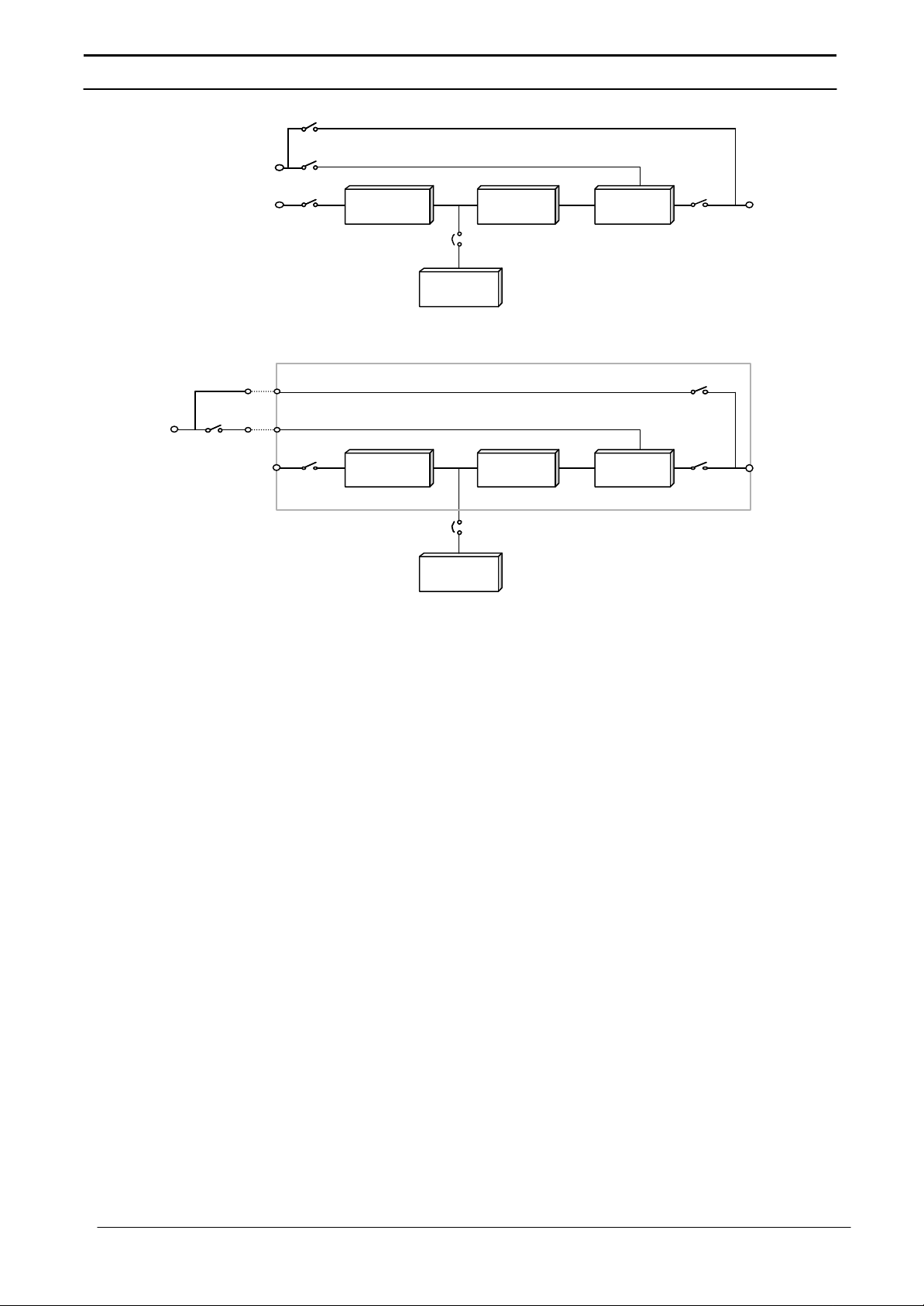
Figure 2: Series 7400 UPS Isolator configurations
Maintenance Bypass
Isolator
Maintenance Bypass Line
Bypass
Supply
Mains
Supply
Bypass
Supply
Bypass
Isolator
Mains
Supply
1.2.3 Bypass Supplies
Bypass Isolator
Static Bypass Line
Input
Isolator
RECTIFIER
INVERTER
Battery
Breaker
STATIC
SWITCH
Output
Isolator
UPS
Output
Supply
BATTERY
A. BLOCK SCHEMATIC FOR 230V OUTPUT 1PH. UPS SYSTEM
Maintenance Bypass Line
Static Bypass Line
Maintenance Bypass
Isolator
Input
Isolator
RECTIFIER
INVERTER
STATIC
SWITCH
Output
Isolator
UPS
Output
Supply
Battery
Battery
Breaker
Breaker
BATTERY
B. BLOCK SCHEMATIC FOR 110V OUTPUT 1PH. UPS SYSTEM
The circuit block annotated ‘Static Switch’ in figure 2 contains an
electronically controlled switching circuit, which enables the critical
load to be connected either to the Inverter output or to a Bypass
power source via the ‘static bypass line’. Normally, the load is
connected to the inverter; but in the event of a UPS overload, or
inverter failure, it is automatically transferred to the static bypass
line due to static switch action. Note that the Bypass supply should
be in normal condition and enabled.
To provide a clean (no-break) load transfer between the inverter
output and static bypass line, the inverter output and bypass supply
must be fully synchronised during normal operating conditions.
This is achieved through the inverter control electronics which
make the inverter frequency track that of the static bypass supply provided that the bypass remains within an acceptable frequency
window. The synchronising window is pre-selected to 2% of
nominal frequency, giving an acceptable frequency window of
±1Hz.
A warning message [INVERTER UNSYNCHRONIZED] is displayed
on the operator control panel when the inverter and bypass
supplies are not synchronized.
A second, manually controlled, ‘Maintenance bypass’ supply is also
incorporated into the UPS design. Its purpose it to enable the
critical load to be powered from the mains (bypass) supply while
the UPS is shut down for maintenance or troubleshooting.
Note:- The load is unprotected against mains power supply aberrations or
failure when it is connected to either the static bypass or maintenance bypass
supply.
3

Series 7400 Single Phase 1+N U PS
1.2.4 UPS Power
Switch
1.2.5 Battery Circuit
Configuration
Breaker
Figure 2 illustrates what is known as the “Split Bypass”
configuration. This is the standard configuration for all 1PH Models
In the “Split Bypass” configuration the static bypass line is switched
by a separate isolator to a dedicated ‘Bypass’ power source which
also feeds the maintenance bypass line.
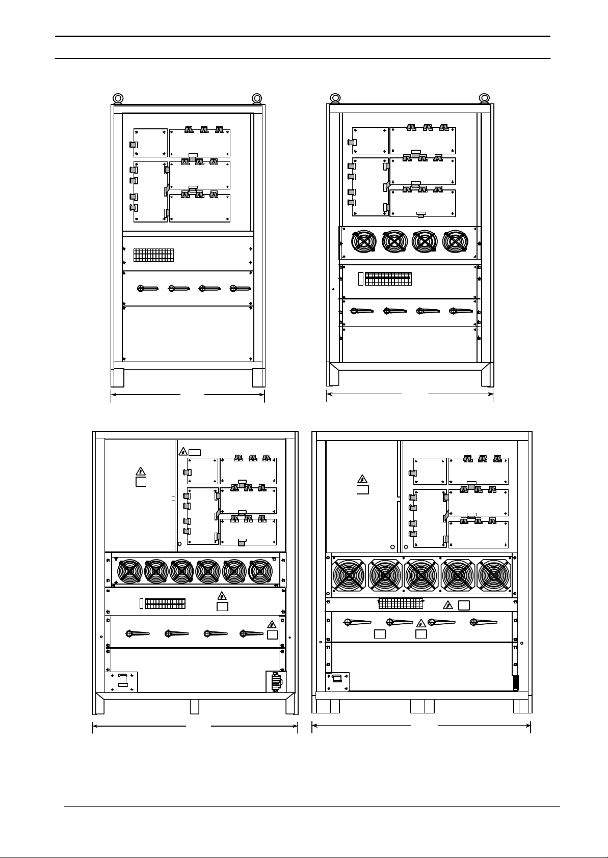
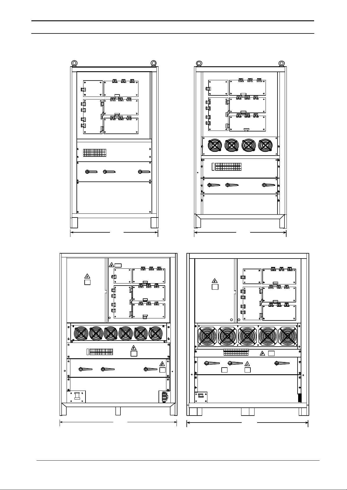
The power switch locations in the various 7400 models are shown
in Figure 3.
With the exception of the maintenance bypass isolator, all the
isolators shown must be closed during normal UPS operation.
Although it cannot be classified as a ‘power’, the reset switch may
be used as a part of the UPS operating procedure. Fitted to the
UPS Logic Board, the reset switch is used by the operator to retransfer the load to the inverter following a detected overload or
overtemperature fault.
The battery is connected to the DC Busbar through a circuit
breaker fitted inside the battery Cabinet / Rack or located adjacent
to the batteries where a battery Cabinet / Rack is not used. This
circuit breaker is closed manually, but it contains an undervoltage
release coil which enables it to be tripped from the UPS control
electronics following certain detects for faults. It also has a
magnetic trip facility for overload protection.
4
Series 7400 Single Phase 1+N U PS
Figure 3A: Power Isolator identification for 230V output system
10/ 40 kVA
50 kVA
60/ 80 kVA
105 kVA
I2
Output
Isolator
I3
Maintenance
Bypass
Isolator
830830
I4
Static
Bypass
Isolator
I1
Input
Isolator
I4
I4
Output
Output
Isolator
Isolator
I3
I3
Maintenance
Maintenance
Bypass
Bypass
Isolator
Isolator
900900
I2
I2
Static
Static
Bypass
Bypass
Isolator
Isolator
I1
I1
Input
Input
Isolator
Isolator
I4
Output
Isolator
I3
Maintenance
Bypass
Isolator
I2
Static
Bypass
Isolator
12501250
I1
Input
Isolator
I4
Output
Isolator
I3
Maintenance
Bypass
Isolator
14001400
I2
Static
Bypass
Isolator
I1
Input
Isolator
5
Series 7400 Single Phase 1+N U PS
Figure 3B: Power Isolator identification for 110V output system
10/ 40 kVA
50 kVA
60/ 70 kVA
105 kVA
I2
Output
Isolator
I3
Maintenance
Bypass
Isolator
830830
I1
Input
Isolator
I4
Output
Isolator
I3
Maintenance
Bypass
Isolator
900900
I1
Input
Isolator
I4
Output
Isolator
I3
Maintenance
Bypass
Isolator
12501250
I1
Input
Isolator
I4
Output
Isolator
I3
Maintenance
Bypass
Isolator
14001400
I1
Input
Isolator
6

Series 7400 Single Phase 1+N U PS
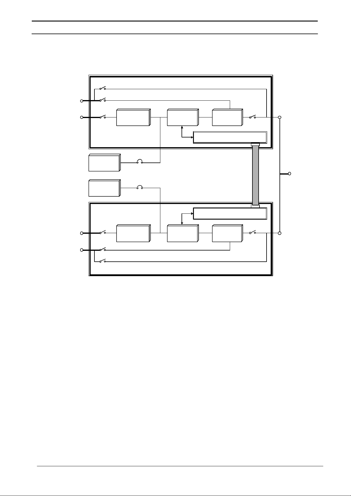
1.2.6 One plus One
Parallel
Control
When two of the standard 7400 modules just described are
connected together to form a one-plus-one system, each module
is fitted with an additional circuit board which allows the two
modules to communicate with each other. Communication takes
place via a single ribbon cable connected between the modules as
illustrated in figure 4.
Note: - Modifying a standard module for use with a one-plus-one system also
involves replacing certain other circuit boards with modified versions, and
relocating certain minor assemblies. This means that although it is not
impossible to modify an existing 7400 module to form part of a one-plus-one
system it is not a straightforward proposition.
The inter-module parallel control responsibilities are complex but
can be summarised as follows:
Synchronisation:
As the outputs from both UPS modules are connected together to
provide a single load supply, it is imperative that the inverters are
fully synchronised both in frequency and phase. This is achieved by
digitally locking the two inverter control oscillators. Similarly, as has
already been mentioned, it is necessary for the inverters to be
synchronised to the bypass supply to enable a “no-break” transfer
to be achieved when the static switch transfers the load to the
bypass supply. The inverter control oscillators are therefore not
only locked together but are also made to track the bypass
frequency.
Current sharing:
The parallel control circuit compares the module’s output current
with that of its partner and is thereby able to effect current sharing
between the modules by making fine adjustments of an individual
module’s output voltage.
Redundancy configuration:
A link in the parallel control logic determines whether the one-plusone system operates in a “redundant” or “non-redundant”
configuration. If a non-redundant mode is selected the two static
switch sections are effectively locked together in that both the
static switches are turned off or on by a single control signal. Thus
if one module develops a fault, when running, its static switch
control logic will transfer its output from the inverter to the static
bypass line and simultaneously send a signal to the static switch
control logic in the second module to do likewise. This does not
happen if the system is configured as a redundant system, in
which case the second module is allowed to continue supplying the
load from its inverter when the first module trips its inverter off line.
Reverse current:
A reverse current monitor circuit detects current flowing into, rather
than out of, the module’s output terminals. Such a condition can
arise if a module develops an internal power fault or if for some
reason the two modules become unbalanced, and is liable to
further damage the module and also degrade the load supply. If a
reverse current is detected the inverter on the affected module is
immediately shut down and load transferred to the bypass supply
depending on the system redundancy configuration.
7
Series 7400 Single Phase 1+N U PS
Figure 4: Parallel control in a one-plus-one system
Bypass
Supply
Mains
Supply
Mains
Supply
Bypass
Supply
BATTERY
BATTERY
RECTIFIER
INVERTER
RECTIFIER
INVERTER
Battery charge current sharing:
The illustration in figure 4 shows a dedicated battery installation for
each module; however, it is possible to fit an option kit which allows
the two modules in a one-plus-one system to share a common
battery. Such an installation is shown in figure 5 overleaf.
STATIC
SWITCH
1+1 PARALLEL CONTROL
UPS
Output
Supply
1+1 PARALLEL CONTROL
STATIC
SWITCH
8

Series 7400 Single Phase 1+N U PS
Figure 5: ‘Common Battery’ configuration
Bypass
Supply
Mains
Supply
BATTERY
Mains
Supply
Bypass
Supply
1.2.7 Common Battery
RECTIFIER
INVERTER
Logic
Control
Common Batt. Panel
RECTIFIER
INVERTER
A “Common battery” option kit contains a DCCT (DC Current
Transformers) which are fitted to the battery power lines and
monitored by the parallel control logic. Each module monitors its
battery charge current and compares it with the charge current
provided by the other module. This enables a module to match its
charge current to that of its partner by effecting fine voltage control
over the rectifier section.
The components used by the Common Battery Option are
contained in a separate cabinet known as the Common Battery
Panel.
STATIC
SWITCH
1+1 PARALLEL CONTROL
UPS
Output
Supply
1+1 PARALLEL CONTROL
STATIC
SWITCH
9
Series 7400 Single Phase 1+N U PS
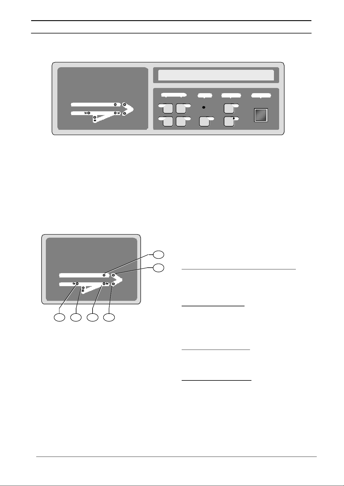
Figure 6: Operator Control Panel
1.2.8 Operator Control
Figure 7: Mimic Panel
Uninterruptible Power System
=
=
The operator control panel is divided into three functional areas;
Panel
‘Mimic indications’, Control switches’, and ‘LCD display panel’.
Uninterruptible Power System
=
LS1 LS2 LS4 LS6
=
MEASUREMENTS
Vo
f
LS3
LS5
ALARM
Io
B ON
INVERTER EMERGENCY
OFF
((•))
Mimic Indications
Six LEDs are mounted on a single line
diagram to represent the various UPS
power paths. These LEDs, which are
annotated in figure7, show the current UPS
operational status and should be
interpreted as detailed below.
LSI - Input supply OK / Rectifier operative:
This led illuminates when the input isolator
(I1) is closed, the input supply is within 20%
of nominal voltage, and the rectifier is
operative.
LS2 - Battery volts OK:
This led illuminates when the battery circuit
breaker is closed and the battery voltage is
within the UPS operating range - 320V432V nominal. (330V - 445V* nominal for
the 80 to 125 kVA Models).
LS3 - Bypass supply OK:
This led illuminates when the static bypass
supply in within 10% of its nominal voltage
and the static bypass isolator is closed.
LS4 - Inverter-output OK:
This led illuminates when the inverter is
operating and its output is within a preset
acceptable voltage window.
* - In case of battery on boost, this voltage can go upto 475V.
10
Series 7400 Single Phase 1+N U PS
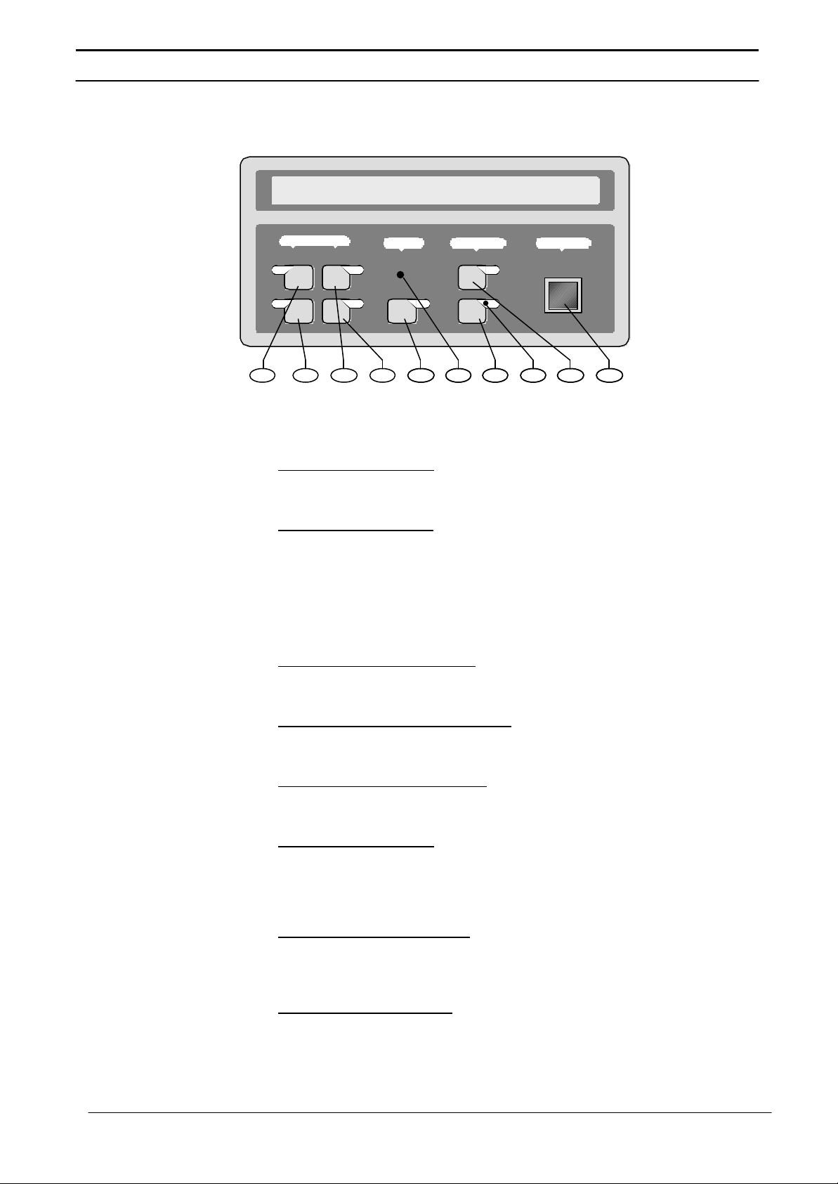
Figure 8: Control Panel Switches
MEASUREMENTS
Vo
f
ALARM
Io
B ON
((•))
INVERTER EMERGENCY
OFF
S2 S3 S4 S5 LS7 S7 LS8 S6 S8
S1
LS5 - Load on bypass:
This led illuminates when the output isolator is closed and the load
is connected to the bypass via the static switch.
LS6 - Load on Inverter:
This led illuminates when the output isolator is closed and the load
is connected to the inverter via the static switch.
Control switches
Seven tactile switches are located on the Operator Panel, together
with an emergency stop push button which is fitted with a safety
cover to prevent inadvertent operation.
Switch S1 (Vo) - Output volts:
When this switch is pressed, the lower line of the LCD Display
shows the output phase voltage w.r.t neutral.
Switch S2 (Fo) - Output frequency:
When this switch is pressed, the lower line of the LCD Display
shows the output frequency.
Switch S3 (Io) - Output current:
When this switch is pressed, the lower line of the LCD Display
shows the output current.
Switch S4 (B) - Battery:
When this switch is pressed, the lower line of the LCD Display
shows the battery voltage and current. Note that a discharging
current is symbolised by a preceding minus (-) sign, plus autonomy
time is displayed according to % load for SMF batteries.
Switch S5 ((•)) - Alarm reset:
Pressing this switch cancels the audible alarm. The alarm led and
messages will remain active if a detected fault condition is still
present.
Switch S6 - Inverter OFF:
Pressing this switch turns OFF the inverter and causes the load to
be transferred to the static bypass supply.
11

Series 7400 Single Phase 1+N U PS
Switch S7 - Inverter ON:
Pressing this switch activates the inverter and causes the load to
be transferred to the inverter side of the static switch after the
inverter voltage has had time to stabilise.
Switch S8- Emergency Stop:
When the emergency stop switch is pressed it disables the static
switch block entirely (so removing load power). It also disables the
rectifier and inverter, and trips the battery circuit breaker. Under
normal circumstances it does not remove UPS input power since
this is applied through a manually controller isolator; however, if the
UPS input supply is connected via a circuit breaker having an
electrical trip facility the emergency stop signal can be used to
drive the external circuit breaker’s trip circuit.
There are two LEDs contained within the switch panel area:
LS7 Alarm:
This led accompanies the audible alarm warning when any alarm
condition is initiated. The audible warning can be cancelled by the
reset switch (S5) but LS7 will only extinguish after the alarmed
condition has reverted to normal.
LS8 - Inverter status:
This green led situated near the inverter ON switch illuminates
when the inverter is selected ON.
12
 Loading...