


 Loading...
Manual Supplement
00809-0500-4530, Rev AA
October 2010
Rosemount 5300/5400 Series
Rosemount 5300/5400 Series with HART to Modbus Converter
Safety Messages . . . . . . . . . . . . . . . . . . . . . . . . . . . . . . . . . page 1-2
Introduction . . . . . . . . . . . . . . . . . . . . . . . . . . . . . . . . . . . . . page 1-3
Workflow . . . . . . . . . . . . . . . . . . . . . . . . . . . . . . . . . . . . . . . page 1-3
Mechanical Installation . . . . . . . . . . . . . . . . . . . . . . . . . . . page 1-4
Electrical Installation . . . . . . . . . . . . . . . . . . . . . . . . . . . . . page 1-4
Establish HART Communication . . . . . . . . . . . . . . . . . . . . page 1-10
Transmitter Configuration . . . . . . . . . . . . . . . . . . . . . . . . . page 1-13
Modbus Communication Protocol Configuration . . . . . . page 1-14
Alarm Handling . . . . . . . . . . . . . . . . . . . . . . . . . . . . . . . . . . page 1-22
Common Modbus Host Configuration . . . . . . . . . . . . . . . page 1-25
Specific Modbus Host Configuration . . . . . . . . . . . . . . . . page 1-30
Troubleshooting . . . . . . . . . . . . . . . . . . . . . . . . . . . . . . . . . page 1-34
HMC Firmware Upgrade in Rosemount Radar Master . . page 1-35
Specifications . . . . . . . . . . . . . . . . . . . . . . . . . . . . . . . . . . . page 1-40
This instruction is a supplement to the Rosemount 5300 Series Reference
Manual (Document No. 00809-0100-4530), and the Rosemount 5400 Series
Reference Manual (Document No. 00809-0100-4026).
www.rosemount.com

Rosemount 5300/5400 Series
Manual Supplement
00809-0500-4530, Rev AA
October 2010
SAFETY MESSAGES
Procedures and instructions in this section may require special precautions to ensure the safety of the personnel performing the operations. Information that
raises potential safety issues is indicated by a warning symbol ( ). Please refer to the following safety messages before performing an operation preceded by this symbol.
Failure to follow safe installation and service guidelines could result in death or serious injury
•Make sure the transmitter is installed by qualified personnel and in accordance with applicable code of practice.
•Use the equipment only as specified in the Rosemount 5300 Series Reference Manual (Document No. 00809-0100-4530), the Rosemount 5400 Series Reference Manual (Document No. 00809-0100-4026), and in this Manual Supplement. Failure to do so may impair the protection provided by the equipment.
•Do not perform any services other than those contained in this manual unless you are qualified.
Explosions could result in death or serious injury
•Verify that the operating environment of the transmitter is consistent with the appropriate hazardous locations specifications.
•To prevent ignition of flammable or combustible atmospheres, disconnect power before servicing.
•Before connecting a HART® or FOUNDATION™ fieldbus based communicator in an explosive atmosphere, make sure the instruments in the loop are installed in accordance with intrinsically safe or non-incendive field wiring practices.
•To avoid process leaks, only use o-ring designed to seal with the corresponding flange adapter.
Electrical shock can result in death or serious injury
•Avoid contact with the leads and terminals. High voltage that may be present on leads can cause electrical shock.
•Make sure the main power to the Rosemount 5300 Series transmitter or Rosemount 5400 Series transmitter is off and the lines to any other external power source are disconnected or not powered while wiring the transmitter.
Probes with non-conducting surfaces
•Probes covered with plastic and/or with plastic discs may generate an ignition-capable level of electrostatic charge under certain extreme conditions. Therefore, when the probe is used in a potentially explosive atmosphere, appropriate measures must be taken to prevent electrostatic discharge.
1-2
Manual Supplement
00809-0500-4530, Rev AA
October 2010
Rosemount 5300/5400 Series
INTRODUCTION |
The Rosemount 5300 Series and Rosemount 5400 Series transmitters are |
|||||||||||
|
|
Modbus compatible measurement devices that support communication with a |
||||||||||
|
|
Remote Terminal Unit (RTU) using a subset of read, write, and diagnostic |
||||||||||
|
|
commands used by most Modbus compatible host controllers. The |
||||||||||
|
|
transmitters also support communication through Levelmaster and Modbus |
||||||||||
|
|
ASCII protocols. |
|
|
|
|
|
|
|
|||
|
|
The HART® to Modbus Converter (HMC) module is located inside the |
||||||||||
|
|
Rosemount 5300 and Rosemount 5400 transmitter enclosure and provides |
||||||||||
|
|
power to and communicates with the transmitter through a HART interface. |
||||||||||
Figure 1-1. System Overview |
|
|
|
|
|
|
|
|
|
|
|
|
|
|
5300/5400 transmitter enclosure |
|
|
||||||||
|
|
|
|
|
|
|
|
|
Modbus and |
|
|
|
|
|
|
|
|
|
|
|
|
||||
|
|
|
|
|
|
|
|
|
Levelmaster |
|
|
|
|
|
|
|
|
|
|
|
|
communication |
Remote |
|
|
|
|
|
|
|
|
|
|
|
|
|
Terminal |
|
|
|
|
|
|
|
|
|
|
|
|
|
|
|
|
|
|
|
|
|
|
|
|
|
Unit |
|
|
|
|
|
HART |
|
|
|
|
|
|
|
|
|
|
5300/5400 |
|
signals |
HART to |
|
|
|
|
|
|
|
|
|
transmitter |
|
|
|
Modbus |
|
|
|
|
|
|
|
|
electronics |
|
|
|
Converter |
|
|
|
|
|
|
|
|
|
|
|
|
|
|
|
HART signals |
Rosemount |
|
|
|
|
|
|
|
|
|
|
|
|
|
Radar Master/ |
|
|
|
|
|
|
|
|
|
|
|
|
Field |
|
|
|
|
|
|
|
|
|
|
|
|
Communicator |
|
|
|
|
|
|
|
|
|
|
|
|||
|
|
During normal operation, the HMC “mirrors” the contents of process variables |
||||||||||
|
|
from the 5300/5400 transmitter to the Modbus registers. To configure the |
||||||||||
|
|
5300/5400 transmitter, it is possible to connect a configuration tool to the |
||||||||||
|
|
HMC. See “Transmitter Configuration” on page 1-13 for more information. |
||||||||||
WORKFLOW |
Overview of workflow for commissioning a Rosemount 5300 or a Rosemount |
|||||||||||
|
|
5400 transmitter with Modbus protocol: |
|
|
||||||||
|
|
1. Mount the transmitter on the tank. |
|
|
||||||||
|
|
2. Connect the power and communication wires. |
|
|
||||||||
|
|
3. Establish HART communication with the transmitter through Rosemount |
||||||||||
|
|
|
Radar Master, or a Field Communicator. This is done by: |
|||||||||
|
|
• Connecting to the HART terminals, or |
|
|
||||||||
|
|
• Connecting to the MA/MB terminals (tunneling mode) |
|
|
||||||||
|
|
4. |
Configure the transmitter. |
|
|
|||||||
|
|
5. Configure the Modbus communication. |
|
|
||||||||
|
|
6. Configure Modbus host. |
|
|
||||||||
|
|
7. Verify output values as reported by the transmitter. |
|
|
||||||||
1-3

Rosemount 5300/5400 Series
Manual Supplement
00809-0500-4530, Rev AA
October 2010
MECHANICAL INSTALLATION
ELECTRICAL INSTALLATION
For instructions on how to mount the Rosemount 5300/5400 transmitter, refer to the Rosemount 5300 Series Reference Manual (Document No. 00809-0100-4530), and the Rosemount 5400 Series Reference Manual (Document No. 00809-0100-4026).
NOTE
For general electrical installation requirements, including grounding requirements, refer to Rosemount 5300 Series Reference Manual (Document No. 00809-0100-4530), and the Rosemount 5400 Series Reference Manual (Document No. 00809-0100-4026).
To connect the Rosemount 5300/5400:
1. Disconnect/shut off the electrical power to transmitter head and then open the instrument cover. Do not remove the cover in an explosive atmosphere with a live circuit.
2.Pull the cable through the cable gland/conduit. For the RS-485 bus, use shielded twisted pair wiring, preferably with an impedance of 120 (typically 24 AWG) in order to comply with the EIA-485 standard and EMC regulations. The maximum cable length is 4000 ft/1200 m.
3.Make sure that the transmitter housing is grounded, then connect wires according to Figure 1-2 and Table 1-1. Connect the lead that originates from the “A” line from the RS-485 bus to the terminal marked MB, and the lead that originates from the “B” line to the terminal marked MA.
4.If it is the last transmitter on the bus, connect the 120 termination resistor.
5.Connect the leads from the positive side of the power supply to the terminal marked POWER +, and the leads from the negative side of the power supply to the terminal marked POWER -. The power supply cables must be suitable for the supply voltage and ambient temperature, and approved for use in hazardous areas, where applicable.
6.Attach and tighten the housing cover. Tighten the cable gland, then plug and seal any unused terminals, and connect the power supply.
1-4
Manual Supplement
00809-0500-4530, Rev AA
October 2010
Rosemount 5300/5400 Series
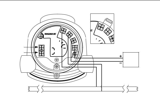
Figure 1-2. Field Wiring Connections
HART to Modbus Converter
|
|
MB |
|
|
MODBUS MA |
- |
|
HART - |
(RS-485) |
||
- |
POWER |
+ |
|
HART + |
HART |
Ambients > 60 ºC |
|
Use wiring rated |
|||
+ |
for min 90 ºC |
|
|
|
|
|
|
120
verter
MB
MODBUS MA
(RS-485) -
In case it is the last transmitter on the bus, connect the 120 termination resistor
Power
Supply
A
120 |
RS-485 Bus |
120 |
B
1-5

Rosemount 5300/5400 Series
Manual Supplement
00809-0500-4530, Rev AA
October 2010
Connection Terminals The connection terminals are described in Table 1-1 below:
Table 1-1. Connection Terminals
Connector label |
Description |
Comment |
|
HART + |
Positive HART connector |
Connect to PC with RRM |
|
|
|
software, Field |
|
HART - |
Negative HART connector |
Communicator, or other |
|
|
|
HART configurators. |
|
MA |
Modbus RS-485 B connection |
|
|
(RX/TX+)(1) |
|
||
|
Connect to RTU |
||
MB |
Modbus RS-485 A connection |
||
|
|||
(RX/TX-)(1) |
|
||
POWER + |
Positive Power input terminal |
Apply +8 Vdc to +30 Vdc |
|
POWER - |
Negative Power input terminal |
(max. rating) |
|
|
|
|
Figure 1-3. Connection Terminals for Rosemount 5300/5400 with HART to Modbus Converter
(1)The designation of the connectors do not follow the EIA-485 standard, which states that RX/TXshould be referred to as 'A' and RX/TX+ as 'B'.
HART to Modbus Converter
|
|
MB |
|
|
|
MA |
|
|
|
MODBUS |
- |
|
|
(RS-485) |
|
HART - |
- |
POWER |
+ |
|
|
HART Ambients > 60 ºC |
|
HART + |
+ |
Use wiring rated |
|
for min 90 ºC |
|
||
|
|
||
1-6
Manual Supplement
00809-0500-4530, Rev AA
October 2010
Rosemount 5300/5400 Series
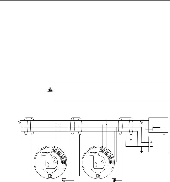
RS-485 Bus
•The 5300/5400 transmitters do not provide electrical isolation between the RS-485 bus and the transmitter power supply
•Maintain a bus topology and minimize stub length
•Figure 1-4 identifies multidrop wiring topology, where up to 32 devices may be wired on one RS-485 bus
•The RS-485 bus needs to be terminated once at each end, but should not be terminated elsewhere on the bus
Installation cases
Install the Rosemount 5300/5400 Series Transmitters as shown in Figure 1-4.
•Use common ground for Modbus Master and Power Supply
•The Power cables and RS-485 Bus are in the same cable installation
•An ground cable is installed and shall be used (cable size ≥4 mm according to IEC60079-14, or size according to applicable national regulations and standards). A properly installed threaded conduit connection may provide sufficient ground.
•The cable shielding is grounded at master site (optional)
NOTE
The HMC equipped transmitter contains intrinsically safe circuits that require the housing to be grounded in accordance with national and local electrical codes. Failure to do so may impair the protection provided by the equipment.
Figure 1-4. Multidrop Connection of
5300/5400 Transmitters
120 |
RS-485 Bus |
HART to Modbus Converter
MB
|
MODBUS MA |
- |
|
(RS-485) |
|
- |
POWER |
+ |
|
HART Ambients > 60 ºC |
|
+ |
Use wiring rated |
|
for min 90 ºC |
|
|
HART to Modbus Converter
MB
|
MODBUS MA |
- |
|
(RS-485) |
|
- |
POWER |
+ |
|
HART Ambients > 60 ºC |
|
+ |
Use wiring rated |
|
for min 90 ºC |
|
|
120
B Modbus
AMaster
Z 
Power Supply
Internal |
|
Internal |
|
Ground Screw |
External |
Ground Screw |
External |
|
Ground Screw |
|
Ground Screw |
1-7

Rosemount 5300/5400 Series
Manual Supplement
00809-0500-4530, Rev AA
October 2010
Alternatively, the Rosemount 5300/5400 Series Transmitters can be installed as shown in Figure 1-5. If this wiring layout is used, there is an increased risk for communication disturbances due to differences in potential between grounding points. By using the same grounding point for Modbus Master and Power Supply, this risk is reduced.
Figure 1-5. Alternative Multidrop
Connection of 5300/5400
Transmitters
120 |
RS-485 Bus |
HART to Modbus Converter
MB
|
MODBUS MA |
- |
|
(RS-485) |
|
- |
POWER |
+ |
|
HART Ambients > 60 ºC |
|
+ |
Use wiring rated |
|
for min 90 ºC |
|
|
HART to Modbus Converter
MB
|
MODBUS MA |
- |
|
(RS-485) |
|
- |
POWER |
+ |
|
HART Ambients > 60 ºC |
|
+ |
Use wiring rated |
|
for min 90 ºC |
|
|
120
B Modbus
A Master
Z
Internal |
Internal |
Ground Screw |
Ground Screw |
External |
External |
Ground Screw |
Ground Screw |
Power
Supply
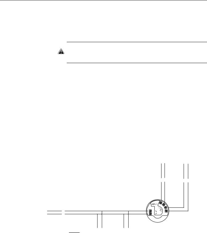
Star Topology
For a Star Topology Connection of the 5300/5400 transmitters, the transmitter with the longest cable run needs to be fitted with a 120termination resistor.
Figure 1-6. Star Topology
Connection of 5300/5400
Transmitters
verter
MB
MODBUS MA
(RS-485) -
For Star Topology connection, connect the 120 termination resistor to the transmitter with the longest cable run.
1-8
Manual Supplement
00809-0500-4530, Rev AA
October 2010
Rosemount 5300/5400 Series
External HART Devices (Slaves)
The HMC supports up to four external HART devices. The external devices are separated by using the HART address. The address must be different between the external devices and only addresses 1 to 5 are allowed for multiple slaves. Connect the devices one at a time and change the short address prior to connecting the next device by using a HART Configuration Tool such as RRM, or a Field Communicator.
NOTE
The power supply from the HMC to external HART devices is not intrinsically safe. In a hazardous environment, any external HART device connected to the HMC must have Flameproof/Explosion-proof certification.
The HMC cyclically polls the HART devices for measurement values. The update rate depends on the number of connected devices and is shown in Table 1-2.
Table 1-2. Approximate update |
|
|
rates for measurement values |
|
|
No. of devices |
Approx. update rate |
|
|
(slaves) |
|
|
|
|
|
1 |
2 seconds |
|
2 |
3 seconds |
|
3 |
4 seconds |
|
4 |
5 seconds |
|
5 |
5 seconds |
Figure 1-7. The HMC Module supports up to four external devices (slaves)
RS-485 |
|
Power |
Bus |
|
Supply |
|
|
|
HART to Modbus Converter
MB
|
MODBUS MA |
- |
|
(RS-485) |
|
- |
POWER |
+ |
|
HART Ambients > 60 ºC |
|
+ |
Use wiring rated |
|
for min 90 ºC |
|
|
Up to four |
|
|
|
external |
External HART |
|
External HART |
devices |
device 2 |
|
device 1 |
|
|
|
|
1-9

Rosemount 5300/5400 Series
Manual Supplement
00809-0500-4530, Rev AA
October 2010
ESTABLISH HART
COMMUNICATION
Connect to the MA/MB terminals
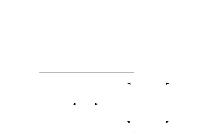
Figure 1-8. RS-485 Communication after startup
The Rosemount 5300 Series and Rosemount 5400 Series can be configured using the Rosemount Radar Master (RRM) PC software or a Field Communicator. Configuration is done by sending HART commands through the HART to Modbus Converter (HMC) to the 5300/5400 transmitter electronics. To establish HART communication, connect to the MA/MB terminals, or to the HART terminals. Both alternatives are described below.
The 5300/5400 level transmitter can be configured with RRM using the MA, MB terminals.
An RS-485 Converter is required to connect to the transmitter.
The transmitter will try to establish communication using different protocols during 20 second timeslots from time of startup.
|
|
|
|
Configured |
|
|
|
Configured |
|
|
|
|
|
|
|
protocol |
|
|
|
protocol |
|
|
|
Modbus RTU |
|
HART |
|
(Modbus RTU, |
|
HART |
|
(Modbus RTU, |
|
|
|
20 seconds |
|
20 seconds |
|
Levelmaster, |
|
20 seconds |
|
Levelmaster, |
|
|
|
|
|
|
|
or Modbus |
|
|
|
or Modbus |
|
|
|
|
|
|
|
ASCII) |
|
|
|
ASCII) |
|
Time |
|
|
|
|
|
20 seconds |
|
|
|
20 seconds |
|||
|
|
|
|
|
|
|
|
|
|
|
|
0 s |
20 s |
40 s |
60 s |
80 s |
100 s |
||||||
The transmitter will continue to use a communication protocol once communication has been established.
1-10
Manual Supplement
00809-0500-4530, Rev AA
October 2010
Rosemount 5300/5400 Series
To configure the 5300/5400 level transmitter using RRM and the MA, MB terminals, do the following:
1.Connect the RS-485 Converter to the MA, MB connectors.
2.Start RRM and open Communication Preferences.
3.Enable HART communication and make sure the port for the RS-485 Converter is selected. Use the following settings:
4.Connect the power wires (or cycle power) to the transmitter.
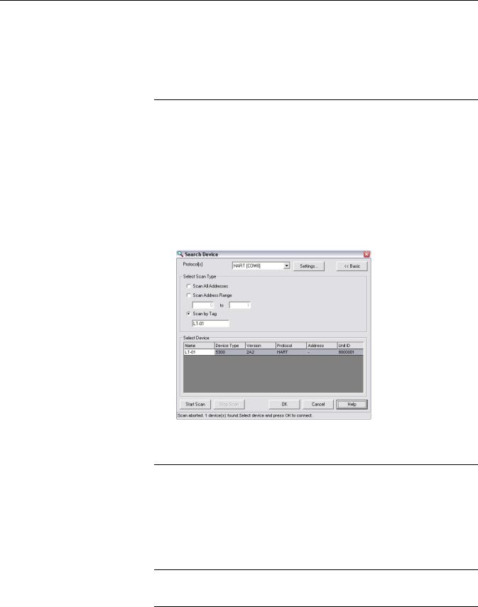
5.Wait 20 seconds and then open the Search Device window in RRM (also see note below). Make sure HART address 1 is being scanned.
1-11
Rosemount 5300/5400 Series
Manual Supplement
00809-0500-4530, Rev AA
October 2010
6.Connect to the transmitter and perform the necessary configuration.
7.After completing the configuration, disconnect the RS-485 Converter, connect the Modbus communication wires and cycle power to the transmitter
8.Verify communication between the transmitter and the RTU is established (can take up to 60 seconds from startup).
NOTE
Take the following into consideration if there are multiple 5300/5400 Modbus units on the bus:
By default, the transmitters have HART address 1. It will not be possible to establish communication on HART address 1 if several transmitters have the same address. In this case, there are alternative solutions to establish communication:
Connect to the HART terminals
1.Select the Scan by Tag option in the Search Device window in RRM and enter the HART Device Tag of the transmitter. Communication can now be established with an individual transmitter even if several devices have the same HART address.
2.Make sure the 5300/5400 transmitter is alone on bus. Disconnect or turn off power from any other devices.
To configure the 5300/5400 transmitter, connect the communicator or PC to the HART terminals using a HART modem, see Figure 1-3 on page 1-6. Both the configuration tool and the RS-485 bus can be connected simultaneously. Configuration data is sent with HART commands through the HMC to the 5300/5400 transmitter electronics, as illustrated in Figure 1-1 on page 1-3. Note that the power supply must be connected during configuration, see also “Electrical Installation” on page 1-4.
NOTE
Measurement data is not updated to the Modbus Master when a configuration tool is connected.
1-12

Manual Supplement
00809-0500-4530, Rev AA
October 2010
Rosemount 5300/5400 Series
TRANSMITTER CONFIGURATION
Configuration data such as Tank Height, Upper Null Zone, dielectric constants, and other basic parameters are configured in the same way as for a standard Rosemount 5300/5400 transmitter. For more information, see the Rosemount 5300 Series Quick Installation Guide (Document No. 00825-0100-4530), and the Rosemount 5400 Series Quick Installation Guide (Document No. 00825-0100-4026).
Make sure that the measurement unit of the Primary Variable (PV) matches the configuration of the Modbus Host since the transmitter output value does not include any information on associated measurement units.
For further information on basic configuration, see the Rosemount 5300 Series Reference Manual (Document No. 00809-0100-4530), and the Rosemount 5400 Series Reference Manual (Document No. 00809-0100-4026).
NOTE
The 5300/5400 transmitter with Modbus protocol is configured to HART address 1 at factory. This reduces power consumption by locking the analog output at 4 mA.
1-13
Loading...