


Installation Manual
 5100 Series, Catalog 5150
Connectivity Module
For use with Automatic Transfer Switches,
Power Manager, & Digital Power Meter
Section |
Page |
Welcome............................................................................................................. |
ii |
Overview, Specifications, Installation Overview, DIP Switch (RS485) |
.............. iii |
Outline and Mounting Drawing .......................................................................... |
iv |
Interface Wiring Diagrams................................................................. |
v, vi, vii, viii |
Status LEDs....................................................................................................... |
ix |
1 |
Installation |
|
|
|
|
Installation Overview, DIP switch (RS485)........................................................ |
|
iii |
|
|
on Automatic Transfer Switches (7000, 4000, 300, 940/962)......................... |
|
1-1 |
|
|
on stand-alone Power Manager, Test Communications ................................. |
|
1-2 |
|
|
View & Change Configuration Pages, View Pages after Installation .............. |
|
1-3 |
|
2 |
7000 & 4000 Series ATS (with & without a Power Manager or Power Meter) |
|||
|
Configurator Screens................................................................................ |
|
2 - 1, 2-2 |
|
|
Detail Screen ................................................................................................... |
|
2-3 |
|
3 |
Series 300 ATS (with & without a Power Manager or Power Meter) |
|
||
|
Configurator Screens................................................................................ |
|
3 - 1, 3-2 |
|
|
Detail Screen ................................................................................................... |
|
3-3 |
|
4 |
ASCO 940 / 962 ATS (with & without a Power Manager) |
|
|
|
|
Configurator Screen ........................................................................................ |
|
4-1 |
|
|
Detail Screen ................................................................................................... |
|
4-2 |
|
5 |
Power Manager & Power Meter (stand-alone, generator, or circuit breaker) |
|||
|
Configurator Screen ........................................................................................ |
|
5-1 |
|
Appendix |
Detail Screens .......................................................................................... |
|
5 - 2, 5-3 |
|
TCP/IP Installation & Configuration for Windows XP ® and Windows 7 ® |
A-1 |
|||
|
||||
|
Troubleshooting............................................................................................... |
|
A-3 |
|
|
Create & copy favorites folder, 3rd Party Modbus ® device configuration........ |
A-4 |
||
|
Enabling SNMP Internet-standard protocol..................................................... |
|
A-5 |
|
|
Communication Address Forms .......................................................... |
in the back |
||
Index ................................................................................................................ |
|
back page |
||
381333-367 B
50 Hanover Rd, Florham Park, NJ 07932-1591 USA |
|
call 1 800 800-2726 (ASC0) for sales or service |
www.ascopower.com |

ii Welcome |
Connectivity Module |
Who Should Use this Installation Manual
This manual for the Connectivity Module should be used to assist individuals who will:
|
|
• install the Connectivity Module (mount and wire) |
||
|
|
• configure the Connectivity Module |
|
|
|
|
• enter in information about your Automatic Transfer Switches |
||
|
|
(7000 & 4000 Series, Series 300, ASCO 940,962,436,434,447,448) |
||
|
|
• use Ethernet access to monitor Connectivity Module (connected devices) |
||
Prerequisites |
A working knowledge of Windows XP ® and Windows Internet Explorer 6.0 or higher |
|||
|
|
(with Microsoft Virtual Machine or the latest version of the Java Runtime Environment |
||
|
|
loaded) is necessary to configure the Connectivity Module. |
||
Important information |
To properly set up the software, you will need the nameplate data and other |
|||
that you will need |
|
information from all your Automatic Transfer Switches including: |
||
|
|
• ATS Name (your designation for the ATS) |
||
|
|
• ATS Location (where the ATS is located in the building) |
||
|
|
• Voltage Rating, Ampere Rating, and number of Poles for each ATS |
||
|
|
• Catalog No. and Serial No. of each ATS |
||
|
|
• Type of ATS (ATS or ATS/BP [ATS with bypass-isolation switch]) |
||
|
|
• Device Address (set in each ATS, Power Manager , or Digital Power Meter) |
||
|
|
|
|
|
|
|
Product |
|
Manuals that you may need |
7000 & 4000 Series ATS & Group 5 Controller |
|
381333-126 & appropriate ATS manual |
||
Series 300, ASCO 940, 962, 436, 434, 447, 448 ATS |
|
appropriate ATS manual |
||
Power Manager Xp, Catalog 5220D, 5220T |
|
381333-199 |
||
Digital Power Meter, Catalog 5210 |
|
381333-368 |
||
Serial Module, Catalog 5110 (Acc. 72A) |
|
381333-240 |
||
ATS Remote Annunciator, Catalog 5310 (1 channel) |
|
381333-316 & 381333-317 |
||
ATS Remote Annunciator, Catalog 5350 (8 channel) |
|
381333-314 & 381333-315 |
||
ATS Remote Annunciator kits 8 channel K871966-004, 1 channel K871966-005
Kits include: ATS Remote Annunciator (RA), Connectivity Module (CM), power supply, mounting hardware, connecting cable The CM can be configured to provide ATS data to ATS Remote Annunciators (RA) over Ethernet either on encryption disabled or enabled mode. Details on how to configure all required parameters for the two modes are in the RA manuals listed above.
Encryption disabled mode is the default operation mode for both the CM and the RA. In this mode, the TCP port and protocol assigned must be the same for both devices.
Encryption enabled mode is when both the CM and RA are configured for AES 128-bit encryption/decryption communication. In this mode, the AES mode and AES port settings in the CM are enabled and assigned a value respectively. Note that the AES port value must be different from the TCP port value (see screen on page 2-1).
Likewise, in the RA, encryption must be enabled and the TCP port is assigned with the same value as the AES port of the CM. Note that the encryption works only on RAs with software version -003 or higher (refer to Configuration, Annunciator screen).
Tip Ö |
Communication Address form is included at the back to help you fill in needed information on your |
|
Connectivity Modules, ATSs, Power Managers, Digital Power Meters. |
The Connectivity Module provides Ethernet-access that allows users to view data from ASCO automatic transfer switches, Power Managers, and Digital Power Meters. All users must follow these precautions:
!DANGER
NOTICE
To avoid possible shock, burns, or death, deenergize all electrical sources to the ATS before installing the Connectivity Module.
Be sure that Users to whom you give access are those persons that you want to view information about the electrical system.
Windows and Internet Explorer are registered trademarks of Microsoft Corporation.

Connectivity Module |
Overview, Specifications, Installation Overview, DIP Switch iii |
Overview
The Connectivity Module brings together several different serial devices that communicate at different baud rates and with different protocols to a common Ethernet media. It can communicate with up to eight clients, such as Web applications (web pages), Vpi, or third-party Modbus ® devices simultaneously over Ethernet media.
Specifications
Power Requirements: |
24 V dc nominal (8 – 28 V dc) |
||
|
1.5 Watt, UL Class 2 power supply, if needed. |
||
Mounting: |
|
|
35 mm DIN rail |
Dimensions: |
3.5” H, 2.8” W, 2.9” D (8.9 cm, 7.1 cm, 7.4 cm) |
||
Field Communication Cable Requirements: |
|||
Ethernet: |
Belden 7882A or equiv. UTP CAT 5 with |
||
|
RJ45 connectors (untwisted pair or higher) |
||
Serial: |
Belden 9842, 9829, 89729, 82729 or Apha |
||
|
6202C, 6222C, 58902. UL Listed, stranded, |
||
twisted pairs, over-all foil shield with stranded drain wire |
|||
J1, J2 TTL Port Connectors: |
Two built-in TTL ports |
||
|
(DB9 pin male) for ATS/PM connectivity |
||
J3 Ethernet Port Connector :
One built-in 10 Base T (RJ45) 10 Mbps Ethernet port
J4 Serial RS-485 Port:
One 5-pin terminal block header with a socket block (J4) designed to be daisy chained for up to 32 devices.
Terminal 1 |
– RX+ |
Terminal 4 |
– TX- |
Terminal 2 |
– RX- |
Terminal 5 |
– Com |
Terminal 3 |
– TX+ |
|
|
Ambient Temperature: |
|
Operating |
32 to 140° F (0 to 60° C) |
Storage - |
-40 to 185° F (-40 to 85° C) |
Configuration Parameters: The parameters that are required to make an Ethernet connection are:
IP Address |
169.254.1.1 |
Subnet Mask |
255.255.0.0 |
Gateway0.0.0.0 |
|
TCP Port No. |
10001 |
The TCP port is used for passing the data to the applications and is configurable for user specific requirement.
Baud Rates |
19200 (default) or 9600 |
Flow Control |
No Flow Control (default) |
Interface Mode |
TTL/RS485 – 4 wires (default) |
Reply Timeout |
200 milliseconds (default) |
Protocol Support: The following protocols are supported:
Serial Protocol: |
|
ASCO I, II, and Modbus |
Transport Protocol: |
TCP, UDP |
|
Application Protocol: HTTP, Telnet, Modbus/TCP |
||
AES Encryption |
enable or disable |
|
Installation Overview
1.Determine the kind of network to use to connect the various devices to the Connectivity Module.
2.If a RS485 network will be used, do not install the Connectivity Module until the DIP switches are checked and set on the bottom of the unit. See below.
3.Refer to the outline & mounting drawing (page iv) and wiring diagrams (pages v, vi).
4.Select the appropriate installation (pages 1-1, 1-2) that corresponds to the product to be connected.
5.Establish and test communications (page 1-2). Refer to Status LEDs (page vii).
6.View and change configuration pages (page 1-3).
Check the DIP Switch Settings for RS485
For RS485 networks only, before installing the Connectivity Module check the position of the DIP switch actuators on the bottom of the unit. The upper two actuators turn on a built-in termination resistor, if needed. The lower two actuators select either a 2-wire or 4-wire RS485 network. See the figure below.
Termination Resistor, upper two actuators
On a daisy chained RS485 network the Connectivity Module termination resistor must be ON. Likewise only the farthest device from the Connectivity Module must have the termination resistor ON. All other devices must be OFF. The DIP switch upper two actuators control the built-in termination resistor:
ON – move to left. OFF – move to right.
2-Wire or 4-Wire network, lower two actuators
If a 2-wire RS485 network is to be attached to the Connectivity Module, move the lower two actuators to the left. If a 4-wire RS485 network is used, move these actuators to the right.
DIP Switch on bottom of unit
Modbus is a registered trademark of Gould Inc.

iv Outline and Mounting Drawing |
Connectivity Module |

v Wiring Diagrams |
Connectivity Module |
|
|
Connectivity Module |
Wiring Diagrams vi |
|
|

vii Wiring Diagrams |
Connectivity Module |
|
|

Connectivity Module |
Wiring Diagrams viii |
Connectivity Module |
Status LEDs ix |
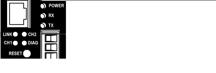
Status LEDs
LED |
LED Description |
LED Function / Mode of Operation |
|
POWER |
Power indication status. |
Solid GREEN – functioning as a Connectivity Module (Acc. 72E). |
|
|
|||
GREEN/AMBER |
Solid AMBER – functioning as a Serial Module (Acc. 72A). |
||
|
|||
|
|
||
|
|
|
|
RX |
Data receiving status. |
Blinking GREEN – indicates receiving data from a client. |
|
GREEN |
|||
|
|
||
|
|
|
|
TX |
Data transmit status. |
Blinking GREEN – indicates transmitting data to a client. |
|
GREEN |
|||
|
|
||
|
|
|
|
LINK |
Link status. |
Solid GREEN – indicates active Ethernet connection. |
|
GREEN |
|||
|
|
||
|
|
|
|
CH1 |
Client connection status. |
Blinking GREEN – indicates active Ethernet client connection. |
|
GREEN |
|||
|
|
||
|
|
|
|
|
|
Blinking YELLOW then off – indicates server disconnection because of |
|
CH2 |
Additional Diagnostic LED. |
Ethernet client inactivity. |
|
|
|||
YELLOW |
Solid YELLOW then off – indicates server disconnection due to Ethernet |
||
|
|||
|
|
||
|
|
client disconnection. |
|
|
|
|
|
|
|
Off – indicates no error. |
|
|
Diagnostic. |
Short blinking RED then off – indicates active client/server write process. |
|
DIAG |
|
||
RED |
Long blinking light then off – indicates server is receiving unrecognized |
||
|
|||
|
|
request packet from an Ethernet client. |
|
|
|
Solid RED – indicates major error. |
|
|
|
|

1-1 Installation
How to Install the Connectivity Module
on 7000 & 4000 Series and Series 300 ATSs
The Connectivity Module (CM) mounts on a DIN rail under the ATS Controller (Group 5 & 1). A short serial cable connects the CM to the Controller. If a Power Manager (PM) or Digital Power Meter (DPM) is present, a long serial cable connects the CM to the PM. Refer to installation drawings provided and follow the steps below to install the Connectivity Module.
Connectivity Module Kit |
Connectivity Module Kit |
|||
K889950 |
K889950-001 for |
|||
for 7000 & 4000 Series |
7000 & 4000 Series |
|||
and Series 300 only |
and Series 300 |
|||
|
|
with PM or DPM |
||
Connectivity |
629800-004 |
Connectivity |
629800-004 |
|
Module 5150 |
Module 5150 |
|||
|
|
|||
DIN Rail and |
754607 |
DIN Rail and |
754607 |
|
Hardware |
Hardware |
|||
|
|
|||
10-in. Serial |
|
10-in. Serial |
|
|
Cable for |
629798-001 |
Cable for |
629798-001 |
|
Controller |
|
Controller |
|
|
|
|
4-ft Serial |
|
|
|
|
Cable for |
629798-002 |
|
|
|
PM or DPM * |
|
|
|
* A 9-foot serial cable (629798-004) is |
|||
|
required for G7ATB, G7ACTB, G7ADTB. |
|||
! DANGER
To avoid possible shock, burns, or death, deenergize all electrical sources to the ATS before installing the Connectivity Module.
1.De-energize both Normal and Emergency sources that feed the ATS. Open enclosure door and check with a non-contact AC voltage detector.
2.Mount the DIN rail (supplied in the kit) onto two studs (on the door) below the Controller. Connectivity Module will mount on the right side.
3.Install Connectivity Module onto DIN rail by hooking the bottom of module on bottom of DIN rail and rocking it upward unit it snaps in place.
4.Install the 10-inch serial cable between the Controller receptacle (J7 on Group 5, J4 on Group 1) and the Connectivity Module J1 receptacle.
5.If a PM (or DPM) is present, connect the 4-foot serial cable between the PM J5 receptacle (or DPM J2 receptacle) and the Connectivity Module J2 receptacle.*
Now test communications (go to page 1-2).
Connectivity Module
How to Install the Connectivity Module on ASCO 940/962 ATSs
The Connectivity Module (CM) mounts on a DIN rail near the ATS Control Panel. A separate power supply is needed unless it is connected to a Power Manager (PM). Group 6A/7A Control Panel must have a Serial Communication Kit added. A single communication cable (2 twisted pairs and overall shield connects the CM to the Control Panel). Refer to installation drawings provided and follow the steps below to install the Connectivity Module.
Connectivity Module Kit |
Connectivity Module Kit |
|
|||||
K889953 |
|
K889953-001 |
|
||||
for ASCO 940/962 only |
for ASCO 940/962 with PM |
|
|||||
Connectivity |
|
629800-004 |
Connectivity |
629800-004 |
|
||
Module 5150 |
|
Module 5150 |
|
||||
|
|
|
|
|
|
||
DIN Rail and |
|
|
754610 |
DIN Rail and |
754610 |
|
|
Hardware |
|
|
Hardware |
|
|||
|
|
|
|
|
|
||
Serial Com. |
|
|
|
|
Serial Com. |
|
|
Kit for Group |
|
|
467508 |
Kit for Group |
467508 |
|
|
6A/7A CP * |
|
|
|
|
6A/7A CP * |
|
|
|
|
|
|
|
Serial Cable |
629798-002 |
|
|
|
|
|
|
for PM |
|
|
|
|
|
|
|
|
|
|
* Serial |
communication & |
transient protection |
boards. |
||||
|
|
|
|
Communication Cable |
|
||
Required |
|
|
|
|
|||
Power Supply ** |
(4 wires and an overall shield) |
|
|||||
not supplied |
|
|
not supplied |
|
|||
24 Vdc, 80 mA ** use |
Belden 9842, 9829, 89729, 82729 or |
|
|||||
16 AWG wire |
|
Alpha 6202C, 6222C, 58902 only |
|
||||
** If a Power Manager (PM) is present, a power supply is not needed for the Connectivity Module (CM). The serial cable from the PM provides the power to the CM.
! DANGER
To avoid possible shock, burns, or death, deenergize all electrical sources to the ATS before installing the Connectivity Module.
1.De-energize both Normal and Emergency sources that feed the ATS. Open enclosure door and check with a non-contact AC voltage detector.
2.Mount DIN rail (supplied in the kit) onto two studs (on the door) below or adjacent to the Control Panel.
3.Install the Connectivity Module onto DIN rail.
4.Prepare and connect the specified communication cable between the Control Panel terminals and the Connectivity Module J4 terminals as listed below:
5.Prepare and connect the 24 Vdc power supply to the Connectivity Module. Use 16 AWG wiring to J5 terminal plug (1 is + positive, 2 is – negative).
Now test communications (go to page 1-2).
 Loading...