


600 A
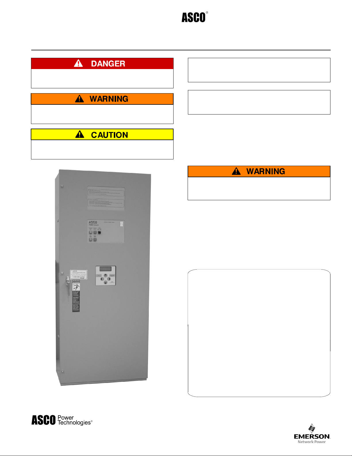
Operator’s
7000 Series A T S
Automatic T ransfer Switches
Manual
DANGER is used in this manual to warn of high
voltages capable of causin g shock, burns, or death.
WARNINGisusedinthismanualto
warn of possible personal injury.
CAUTIONisusedinthismanualto
warn of possible equipment damage.
J–desi gn , 260, 400, & 600 A
Refer to the outline and wiring drawings provided
with your 7000 Series ATS for all installation and
connection details and accessories.
Refer to Group 5 Controller User’s Guide
381333–126 for ATS status display messages, time
delays, pickup & dropout settings, and adjustments.
Rating Label
Each automatic transfer switch (ATS) has a rating label to
define the loads and fault circuit withstand/closing ratings.
Refer to the label on the transfer switch for specific values.
Do not exceed the values on the rating label.
Exceeding the rating can cause personal injury
or serious equipment damage.
260 amp. size
Nameplate
The Transfer Switch nameplate includes data for each
specific ASCO 7000 Series ATS. Use the ATS only within
the limits shown on this nameplate.
An experienced licensed electrician must install the ATS.
TABLE OF CONTENTS
section-page
INSTALLATION 1-1........................
Mounting and Line Connections 1-1.........
Auxiliary Circuits and Harness 1-2...........
Engine Starting Contacts 1-2...............
Functional Test 1-2 through 1-5..............
TESTING & SERVICE 2-1..................
Transfer Test 2-1..........................
Preventive Maintenance 2-1................
Disconnecting the Controller 2-1............
Manual Load Transfer 2-2..................
Trouble-Shooting 2-2......................
INDEX back cover.........................
50 Hanover Road, Florham Park, New Jersey 07932–1591 USA
For sales or service call 1 800 800–2726 (ASCO) www.ascopower.com
ASCO POWER TECHNOLOGIES CANADA PO Box 1238, 17 Airport Road, Brantford, Ontario, Canada N3T 5T3
telephone 519 758–8450, fax 519 758–0876, for service call 1 888 234–2726 (ASCO) www.asco.ca
381333–283 B
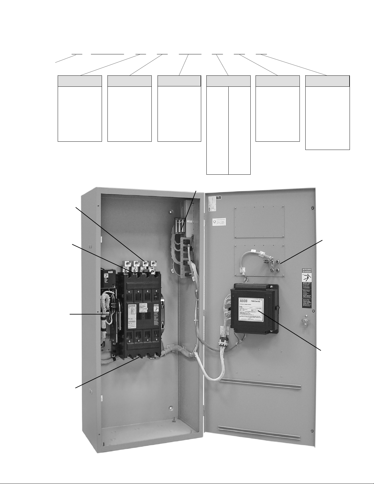
Catalog Number Identification
A typical Catalog Number is shown below with its elements explained. The example is for a 7000 Series 7ATS
with overlapping neutral, 3 pole, 600 amp, 480 V, in a Type 1 enclosure:
design
prefix
letter
A –solid
B –switched
C – overlapping
blank – none
load power
connections
J
Neutral
7ATS C 3 600 N 5 C
Phase Poles
2 –singleØ
3 –threeØ
Amperes Voltage Controller Enclosure
260
400
600
A 115
B 120
C 208
D 220
E 230
F 240
G 277
H 380
customer terminals block
J 400
K 415
L 440
M 460
N 480
P 550
Q 575
R 600
5 –standard
5X –if
accessories
ordered
C –type1
F –type3R
G –type4
H –type4X
L –type12
blank – open type
emergency
power
connections
Transfer
Switch
normal power
connections
transfer
control
&lights
Controller
260 amp. size in typical enclosure with location of customer connections
SECTION 1 INSTALLATION
ASCO 7000 Series Automatic Transfer Switches (ATSs)
are factory wired and tested. Field installation requires
requires mounting and connection of service cables,
and auxiliary control circuits (if required).
Remove the Shipping Skid (large ATSs)
For large ATSs, open the front door and remove the
four lag screws (2 in front, 2 in rear) securing enclosure
to the wood skid.
Supporting Foundation
The supporting foundation for the enclosure must be
level and straight. Refer to the applicable enclosure
outline drawing included with the switch for all
mounting details including door opening space.
If bottom cable entry is used, the foundation must be
prepared so that the conduit stubs are located
correctly. Refer to the enclosure outline drawing for
specified area and location. Provide cable bending
spaceandclearancetolivemetalparts. Whena
concrete floor is poured, use interlocking conduit
spacer caps or a wood or metal template to maintain
proper conduit alignment.
Mounting
Refer to the a pplicable enclosure outline drawing
furnished with this switch and mount the automatic
transfer switch according to details and instructions
shownondiagram.
Testing Power Conductors
Do not connect the power conductors to the transfer
switch until they are tested. Installing power cables in
conduit, cable troughs and ceiling-suspended hangers
often requires considerable force. The pulling of cables
can damage i nsulation and stretch or break the
conductor’s strands. For this reason, after the cables
are pulled into position, and before
connected, they should be tested to verify that they are
not defective or have been damaged during
installation.
Protect the automatic transfer switch from
construction grit and metal chips to prevent
malfunction or shortened life of the ATS.
they are
Connecting Power Conductors
After the power cables have been tested, connect them
to the appropriate terminal lugs on the transfer switch
as shown on the wiring diagram provided with the
switch. Makesurethelugsprovidedaresuitablefor
use with the cables being installed. Standard terminal
lugs are solderless screw type and will accept the wire
sizes listed on the drawings provided with the switch.
Be careful when stripping insulation from the cables;
avoid nicking or ringing the conductor. Remove
surface oxides from cables by cleaning with a wire
brush. When aluminum cable is used, apply joint
compound to conductors. Tighten cable lugs to the
torque specified on rating label.
Line Connections
Refer to the Wiring Diagram provided with the switch.
All wiring must be made in accordance with the
National Electrical Code and local codes.
It is not necessary to remove pole covers from the
transfer switch for cabling. If you do remove them,
reinstall them carefully.
De–energize the conductors before making
any line or auxiliary circuitry connections.
Be sure that Normal and Emergency line
connections are in proper phase rotation.
Place engine generator starting control in the
OFF position. Make sure engine generator is
not in operation.
Controller Ground
A grounding wire must be connected to the controller’s
lower left mounting stud. Because the controller is
mounted on the enclosure door, a conductive strap
must be used between the enclosure and the door. This
connection provides proper grounding which does not
rely upon the door hinges.
Harnesses
The transfer switch is connected to the left side of the
controller by a plug–in harness (two plugs).
1 --- 1
 Loading...