


Gas Valve Cross Reference
for Furnaces, Boilers and Heaters
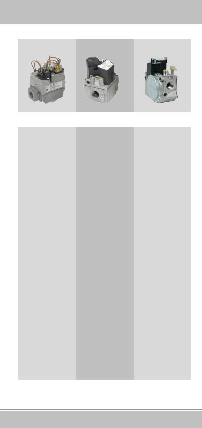
36H
36C 36J
White-Rodgers36Series
Complete online Cross Reference for White-Rodgers and competitive gas valves www.white-rodgers.com
White-Rodgers is the leading manufacturer of gas valves to the OEM. When it’s time to replace – replace with the same brand trusted by OEMs on their equipment!
R-4360

Index |
|
Gas Valve Selection Guide................................................. |
3 |
Range of Operation............................................................. |
5 |
Nomenclature...................................................................... |
6 |
36C.............................................................................. |
6 |
36H.............................................................................. |
7 |
36J............................................................................... |
7 |
System Applications............................................................ |
8 |
Product Features and Specifications.................................. |
11 |
36C.............................................................................. |
11 |
36H.............................................................................. |
12 |
36J............................................................................... |
13 |
Product Accessories............................................................ |
14 |
Gas Valves Cross Reference.............................................. |
15 |
Online Cross Reference
For complete online
Cross Reference
Emerson Climate Technologies Mobile Toolbox
WRMobile™ provides instant access to product replacement information including wiring diagrams, sell sheets, installation and operating instructions for thermostats, gas valves and HVAC controls. Scan and download the App here.
White-Rodgers Technical Support
800-284-2925
White-Rodgers Customer Service
888-725-9797
The White-Rodgers replacement information is provided without charge as a complimentary service and is therefore given on the express understanding and agreement of the recipient that it is given without warranty (express or implied) or liability of any kind. It is the responsibility of the installer to verify that a White-Rodgers replacement is suitable for installation. This may require referring to product installation instructions, contacting the original equipment manufacturer, contacting a qualified service person or other steps. Final responsibility for the selection and application of a control rests solely with the installer.
R-4360 1236
2 Gas Valve Cross Reference

►Gas Valve Selection Guide
What questions need to be asked when matching up gas valves?
1.Type of Valve
1.1Standing Pilot
1.2Intermittent Ignition (Proven/Intermittent Pilot)
1.3Direct Burner Ignition (Spark or Hot Surface)
1.4Single Stage
1.5Two-Stage
2.Pipe Size Both Inlet and Outlet
3.Coil Voltage
3.124V
3.2750 mV
3.3Line Voltage (120 or 240V)
4.Type of gas (LP or Natural)
5.Opening Characteristics of Gas Valve
5.1Fast Opening
5.2Slow Opening
5.3Step Opening
Hot Surface Ignition
24 VAC
|
|
|
|
|
|
|
|
|
|
|
|
|
|
|
|
Fast |
|
Opening |
|
|
|
|
Slow |
|
Opening |
||
|
|
|
|
|
|
|
|
||||||
L |
|
|
|
|
|
|
|
|
|
|
|
|
|
|
|
|
|
|
|
|
|
|
|
|
|
|
|
.P. |
|
|
Nat. |
|
|
L.P. |
|
|
Nat. |
||||
|
|
|
|
|
|
|
|
|
|
|
|
|
|
|
|
36H32 |
|
-423 |
|
|
|
|
36H33 |
|
-412 |
||
|
|
|
|
|
|
|
|
||||||
|
|
|
|
|
|
|
|
|
|
|
|
|
|
All reducer bushings and conversion kits |
|
|
All reducer bushings |
|
and conversion kits |
||||||||
|
|
are included |
|
|
|
|
are included |
||||||
Direct Spark
|
|
|
|
|
|
|
|
|
|
|
SINGLE |
|
|
|
|
|||||||
|
|
|
|
|
|
|
|
|
|
|
STAGE |
|
|
|
|
|||||||
|
|
|
|
|
|
|
|
|
|
|
|
|
|
|
|
|
|
|
|
|
|
|
|
|
|
|
|
Fast |
|
Opening |
|
|
|
Step |
|
Opening |
|
|
|
|
|||||
|
|
|
|
|
|
|
|
|
|
|
||||||||||||
|
|
|
|
|
|
|
|
|
|
|
|
|
|
|
|
|
|
|
|
|
|
|
|
|
|
|
|
|
|
|
|
|
|
|
|
|
|
|
|
|
|
|
|
|
|
|
|
|
L.P. |
|
|
|
|
Nat. |
|
|
|
Nat. |
|
|
|
|
||||||
|
|
|
|
|
|
|
|
|
|
|
|
|
|
|
|
|
|
|
|
|
|
|
|
|
|
|
|
|
36H32 |
|
-423 |
|
|
|
|
36C74 |
|
-913 |
|
|
|
|
|
||
|
|
|
|
|
|
|
|
|
|
|
||||||||||||
|
|
|
|
|
|
|
|
|
|
|
|
|
|
|
|
|
|
|
|
|
|
|
|
|
All reducer bushings and conversion kits |
|
|
All reducer bushings are included |
|
|
|||||||||||||||
|
|
|
|
|
are included |
TWO |
|
|
|
|
||||||||||||
|
|
|
|
|
|
|
|
|
|
|
|
|
|
|
||||||||
|
|
|
|
|
|
|
|
|
|
|
STAGE |
|
|
|
|
|||||||
|
|
|
|
|
|
|
|
|
|
|
|
|
|
|
|
|
|
|
|
|
|
|
|
|
|
|
|
|
|
|
|
|
|
|
|
|
|
|
|
|
|
|
|
|
|
|
|
|
|
|
Relay |
|
|
|
|
|
|
Bimetal |
|
|
|
|
||||||
|
|
|
|
|
|
|
|
|
|
|
|
|
|
|
|
|
|
|
|
|
|
|
|
|
|
|
|
|
|
|
|
|
|
|
|
|
|
|
|
|
|
||||
|
|
L.P. |
|
|
|
Nat. |
|
|
L.P. |
Nat. |
|
|
||||||||||
|
|
|
|
|
|
|
|
|
|
|
|
|
|
|
|
|
|
|
|
|
|
|
|
|
|
|
|
|
|
|
|
|
|
|
|
|
|
|
|
|
|
||||
|
|
|
|
|
|
|
|
|
|
|
|
|
|
|
|
|
|
|
|
|
|
|
|
|
|
|
|
|
|
|
|
|
|
36H64-463 |
|
|
|
|
|||||||
|
|
|
|
|
|
|
|
|
|
|
|
|
|
|
|
|
|
|
||||
|
|
|
|
|
|
|
|
|
All reducer bushings and conversion kits |
|
|
|
|
|
|
|
||||||
|
|
|
|
|
|
|
|
|
|
|
are included |
|
|
|
|
|
|
|
||||
|
|
|
|
|
|
|
|
|
|
|
|
|
|
|
|
|
|
|
|
|
|
|
|
|
|
|
|
|
|
|
|
|
|
|
|
|
|
|
|
|
|
|
|
|
|
Gas Valve Cross Reference 3

►Gas Valve Selection Guide
Standing Pilot
|
|
|
|
|
|
|
|
|
|
|
|
|
FAST |
|
|
|
|
|
|
|
||||
|
|
|
|
|
|
|
|
|
|
|
|
|
OPENING |
|
|
|
|
|
|
|
||||
|
|
|
|
|
|
|
|
|
|
|
|
|
|
|
|
|
|
|
|
|
|
|
|
|
|
|
|
|
|
|
|
|
|
|
|
|
|
|
|
|
|
|
|
|
|
|
|
|
|
|
|
|
Millivolt |
|
|
|
|
24Vac |
|
|
|
120Vac |
||||||||||||
|
L |
|
|
|
|
|
|
|
|
|
|
|
|
|
|
|
|
|
|
|
|
|
|
|
|
|
|
|
|
|
|
|
|
|
|
|
|
|
|
|
|
|
|
|
|
||||
|
.P. |
|
|
|
|
Nat. |
|
|
L.P. |
|
Nat. |
L.P. |
|
|
Nat. |
|||||||||
|
|
|
|
|
|
|
|
|
|
|
|
|
|
|
|
|
|
|
|
|
|
|
|
|
|
|
|
|
|
-433 |
|
|
|
|
|
|
|
|
|
|
|
|
|
|
|||||
|
|
|
36C03U |
|
|
|
|
|
|
36C03-433 |
|
|
|
36C03A-410 |
||||||||||
|
|
|
|
|
|
|
|
|
|
|
|
|
|
|
|
|
|
|
|
|||||
|
|
|
|
|
|
|
|
|
|
All reducer bushings and |
conversion kits are included |
|
|
|
|
|
|
|
||||||
|
|
|
|
|
SLOW |
|
|
|
|
|
|
|
STEP |
|
|
|
|
|
|
|
||||
|
|
|
|
|
OPENING |
|
|
|
|
|
|
|
OPENING |
|
|
|
|
|
|
|
||||
|
|
|
|
|
|
|
|
|
|
|
|
|
|
|
|
|
|
|
|
|
|
|
|
|
|
|
|
24Vac |
|
|
|
|
|
|
|
Millivolt |
|
|
|
|
|
|
|
||||||
|
|
|
L |
|
|
|
|
|
|
|
|
|
|
|
|
|
|
|
|
|
|
|
|
|
|
|
|
|
|
|
|
|
|
|
|
|
|
|
|
|
|
||||||||
|
|
|
.P. |
Nat. |
|
L |
.P. |
Nat. |
|
|
|
|
||||||||||||
|
|
|
|
|
|
|
|
|
|
|
|
|
|
|
|
|
|
|
|
|
|
|
|
|
|
|
|
|
|
36C53 |
|
-418 |
|
|
|
|
|
|
|
|
|
|
|
|
|
|
|
|
|
|
|
|
|
|
|
|
|
|
|
|
36C04U-438 |
|
|
|
|
|
|
|
||||||
|
|
|
|
|
|
|
|
|
|
|
|
|
|
|
|
|
|
|
|
|||||
|
Reducer bushings & conversions kits included |
|
|
Reducer bushings are included |
|
|
|
|
||||||||||||||||
|
|
|
|
|
|
|
|
|
|
|
|
|
|
|
|
|
|
|
|
|
|
|
|
|
Cycle Pilot
24Vac
|
|
|
|
|
|
|
|
|
|
|
|
|
|
|
|
Fast |
|
Opening |
|
|
|
|
Slow |
|
Opening |
||
|
|
|
|
|
|
|
|
||||||
L |
|
|
|
|
|
|
|
|
|
|
|
|
|
|
|
|
|
|
|
|
|
|
|
|
|
|
|
.P. |
|
|
Nat. |
|
|
L.P. |
|
|
Nat. |
||||
|
|
|
|
|
|
|
|
|
|
|
|
|
|
|
|
36C84 |
|
-926 |
|
|
|
|
36C94 |
|
-906 |
||
|
|
|
|
|
|
|
|
||||||
|
|
36C84-945 |
|
|
|
|
|
|
|
|
|||
|
|
36C84-921 |
|
|
All reducer bushings and conversion kits are |
||||||||
|
|
36C84-913 |
|
|
|||||||||
|
|
|
|
|
|
included |
|||||||
|
|
36C84-912 |
|
|
|
|
|||||||
|
|
|
|
|
|
|
|
|
|
||||
|
|
|
|
|
|
|
|
|
|
|
|
|
|
All reducer bushings and conversion kits are |
|
|
|
|
|
|
|
|
|||||
|
|
included |
|
|
|
|
|
|
|
|
|||
4 Gas Valve Cross Reference
►Range of Operation
36C |
|
36H |
|
36J |
|
|
|
|
|
|
|
|
|
|
Applications
|
Direct Spark |
Direct Spark |
Direct Spark |
|
|
Hot Surface Ignition |
Hot Surface Ignition |
Hot Surface Ignition |
|
|
Proven Pilot |
Proven Pilot/ |
|
|
|
Standing Pilot |
Intermittent Pilot |
|
|
|
|
|
|
|
|
|
|
|
|
|
Natural Gas Range of Regulation |
|
|
|
|
50 to 400 KBTU/HR |
50 to 400 KBTU/HR |
40 to 210 KBTU/HR |
|
|
|
|
|
|
|
Opening Characteristic |
|
|
|
|
Fast Open |
Fast Open |
Fast Open |
|
|
Slow Open |
Slow Open |
Slow Open |
|
|
Step Open |
2-Stage Fast Open |
2-Stage Fast Open |
|
|
|
2-Stage Slow Open |
2-Stage Slow Open |
|
|
|
|
|
|
|
Inlet/Outlet Size Options |
|
|
|
|
|
|
|
|
|
|
|
|
|
|
1/2" x 3/8" |
1/2" x 1/2" |
1/2" x 1/2" |
|
|
1/2" x 1/2" |
1/2" x 3/4" |
|
|
|
1/2" x 3/4" |
3/4" x 3/4" |
|
|
|
3/4" x 3/4" |
|
|
|
Gas Valve Cross Reference 5

►36C Nomenclature
36C XX X - XXX
Basic Model Number Series
Specification of options/features (numbered versions)
|
|
|
|
|
|
|
|
|
VOLTAGE LETTER CODING |
|
|
|
|
||||
LETTER |
VOLTAGE |
FREQUENCY |
CURRENT |
|
|
|
TYPE NUMBER |
|
NONE |
24 |
|
60 |
A.C. |
|
NUMBER |
PIPE SIZE (INLET x OUTLET) |
|
A |
120 |
|
60 |
A.C. |
|
1XX |
1⁄2” x 3⁄8” |
|
B |
115 |
|
50 |
A.C. |
|
2XX |
1⁄2” x 1⁄2” |
|
C |
24 |
|
50 |
A.C. |
|
3XX |
1⁄2” x 3⁄4” |
|
G |
240 |
|
60 |
A.C. |
|
4XX |
3⁄4” x 3⁄4” |
|
H |
240 |
|
50 |
A.C. |
|
|
|
|
U |
.750 |
|
-- |
D.C. |
|
|
|
|
MODEL |
TYPE |
REGULATOR |
LINE |
STEP |
OPERATOR |
NUMBER |
GAS |
INTERRUPTER |
|||
36C01 |
NAT |
NO |
NO |
NO |
RELAY |
36C02 |
NAT/LP |
YES |
YES |
NO |
RELAY |
36C03 |
NAT |
YES |
YES |
NO |
RELAY |
36C04 |
NAT |
YES |
YES |
REGULATED |
RELAY |
36C05 |
NAT |
YES |
YES |
REGULATED |
RELAY |
36C10 |
ALL |
NO |
YES |
NO |
RELAY |
36C12 |
NAT/LP |
YES |
YES |
REGULATED |
RELAY |
36C13 |
LP |
YES |
YES |
NO |
RELAY |
36C14 |
LP |
YES |
YES |
REGULATED |
RELAY |
36C15 |
LP |
YES |
YES |
REGULATED |
RELAY |
36C21 |
ALL |
NO |
NO |
NO |
RELAY |
36C27 |
NAT |
YES |
NO |
REGULATED |
RELAY |
36C36 |
NAT/LP |
YES |
NO |
NO |
RELAY |
36C38 |
NAT |
YES |
NO |
NO |
RELAY |
36C40 |
NAT |
YES |
YES |
NO |
RELAY |
36C41 |
LP |
YES |
YES |
NO |
RELAY |
36C53 |
NAT.LP |
YES |
YES |
NO |
RELAY |
36C67 |
NAT/LP |
YES |
YES |
FIXED |
RELAY |
36C68 |
NAT/LP |
YES |
SOLENOID |
NO |
RELAY |
36C74 |
NAT/LP |
YES |
SOLENOID |
REGULATED |
RELAY |
36C76 |
NAT/LP |
YES |
SOLENOID |
NO |
RELAY |
36C77 |
NAT/LP |
YES |
SOLENOID |
FIXED |
RELAY |
36C78 |
NAT/LP |
YES |
SOLENOID |
NO |
RELAY |
36C81 |
NAT/LP |
YES |
SOLENOID |
NO |
RELAY |
36C84 |
NAT/LP |
YES |
SOLENOID |
NO |
RELAY |
36C87 |
NAT/LP |
YES |
SOLENOID |
REGULATED |
RELAY |
36C90 |
NAT/LP |
YES |
SOLENOID |
NO |
RELAY |
36C92 |
NAT/LP |
YES |
SOLENOID |
NO |
RELAY |
36C94 |
NAT/LP |
YES |
SOLENOID |
SLOW |
RELAY |
36D01 |
NAT/LP |
YES |
NO |
FIXED |
RELAY |
36D11 |
ALL |
NO |
SOLENOID |
NO |
RELAY |
36D13 |
NAT/LP |
YES |
SOLENOID |
NO |
RELAY |
36D14 |
NAT/LP |
YES |
SOLENOID |
NO |
RELAY |
36D22 |
NAT |
YES |
YES |
NO |
RELAY |
36D23 |
NAT/LP |
YES |
SOLENOID |
NO |
RELAY |
36D24 |
NAT/LP |
YES |
SOLENOID |
NO |
RELAY |
36D27 |
NAT/LP |
YES |
SOLENOID |
NO |
RELAY |
36D29 |
NAT/LP |
YES |
SOLENOID |
NO |
RELAY |
36D32 |
NAT/LP |
YES |
YES |
NO |
RELAY |
6 Gas Valve Cross Reference

►36H Nomenclature
36H XX X - XXX
Basic Model Number Series 
FEATURES
Model |
Fast Open |
Slow Open |
Direct Ignition |
Proven Pilot |
Single Stage |
Two Stage |
Number |
||||||
36H22 |
X |
|
X |
|
X |
|
36H23 |
|
X |
X |
|
X |
|
36H32 |
X |
|
|
X |
X |
|
36H33 |
|
X |
|
X |
X |
|
36H54 |
X |
|
X |
|
|
X |
36H55 |
|
X |
X |
|
|
X |
36H64 |
X |
|
|
X |
|
X |
36H65 |
|
X |
|
X |
|
X |
TYPE NUMBER CODING
Number |
Pipe Size (inlet x outlet) |
4XX |
3/4" NPT x 3/4" NPT |
3XX |
1/2" NPT x 3/4" NPT |
2XX |
1/2" NPT x 1/2" NPT |
VOLTAGE/FEATURE LETTER CODING
Alpha |
Voltage |
Additional Features |
Numeric |
||
None |
24V 50/60 HZ |
|
|
|
|
►36J Nomenclature
36J XX X - XXX
Basic Model Number Series 
FEATURES
Model |
Fast Open |
Slow Open |
Convertible |
Two Stage |
Number |
||||
36J22 |
X |
|
X |
|
36J23 |
|
X |
X |
|
36J24 |
|
X |
X |
|
36J26 |
|
X |
X |
|
36J29 |
X |
|
X |
|
36J30 |
|
X |
X |
|
36J52 |
|
X |
X |
|
36J54 |
X |
|
X |
X |
36J55 |
|
X |
X |
X |
TYPE NUMBER CODING
Number |
Pipe Size (inlet x outlet) |
|
2XX |
1/2 NPT x 1/2 NPT |
|
Pressure Tap Towers |
||
|
||
5XX |
1/2 NPT x 1/2 NPT |
|
1/8 NPT Press. Taps |
||
|
||
|
|
|
6XX |
1/2 NPT x 1/2 NPT Bottom Outlet |
|
1/8 NPT Press. Taps |
||
|
||
|
|
VOLTAGE / FEATURE LETTER CODING
Alpha Numeric |
Voltage |
Additional Features |
None |
24V 50/60 HZ |
Std. Adj. |
Y |
24V 50/60 HZ |
Limited Max. Adj. Reg. |
|
|
|
Gas Valve Cross Reference 7
►System Applications
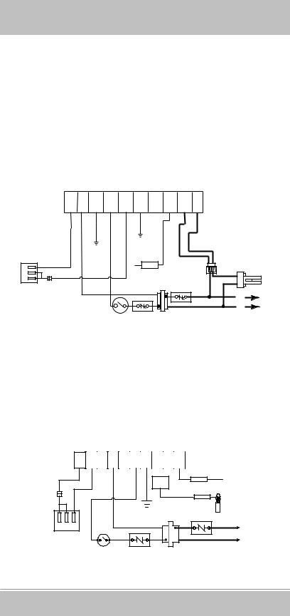
Hot Surface Ignition (HSI)
The thermostat calls for heat and energizes the HSI control. If system is equipped with prepurge, the purge fan is energized and power will be delayed thirty seconds before application to the Hot Surface Ignitor. If prepurge is not selected, the ignitor is powered within one second. The ignitor heats up and at the end of the heating period, the redundant and main valves are opened. A flame must be detected within a fixed time period or both valves close, the ignitor is turned off and the HSI control locks out unless the system is equipped with retry. Retry indicates the ignition sequence will be repeated for a total of three tries if flame is undetected or lost within 30 seconds of ignition.
M |
T |
G |
T |
M |
L |
|
V |
N |
V |
||||
R |
H |
2 |
||||
2 |
D |
1 |
||||
|
|
|
H |
F |
L |
H |
|
S |
S |
|||
P |
1 |
|||
2 |
1 |
|||
|
|
|
BURNER |
|
BLUE |
|
|
GROUND |
|
|
HOT |
|
|
|
RED |
|
|
MV2 |
|
SURFACE |
|
C |
|
ADAPTER |
||
|
IGNITER |
|||
|
FLAME |
|||
P |
MV1 |
|
|
|
M |
PROBE |
|
|
|
External |
|
|
|
|
GAS |
|
LIMIT |
|
|
VALVE |
Jumper |
|
CONTROLLER |
|
|
|
|
|
L1 |
|
|
|
|
(HOT) |
|
|
|
|
L2 |
|
THERMOSTAT OR |
ALTERNATE TRANSFORMER |
|
|
|
CONTROLLER |
LIMIT |
|
|
Typical Wiring for Hot Surface Ignition System
Direct Spark Ignition (DSI)
The thermostat calls for heat and simultaneously energizes the DSI control module and gas valve solenoid. Sparks at the ignition electrodes ignite the gas at the main burner. Flame is sensed through the electrodes by the flame detection circuit and shuts off the sparking. If flame is not established within a fixed time period
(lock-out time) main and redundant valves close, sparking ceases and the control module locks out.
MV |
VAL |
TR |
TH |
GND |
FLY LEAD |
SPARK |
|
|
|
|
|
|
SPARK |
MV |
|
|
|
|
|
PROBE |
|
|
|
|
|
|
(GND) |
FLAME |
FLAME |
|
||
|
|
|
|
|
PROBE |
External |
|
|
Jumper |
|
|
|
Burner Ground |
LIMIT |
|
|
|
|
|
CONTROLLER |
M P C |
(GND) |
L1 (HOT) |
GAS |
|
L2 |
VALVE |
|
|
|
|
|
THERMOSTAT OR |
ALTERNATE TRANSFORMER |
|
CONTROLLER |
LIMIT |
|
Typical Wiring for Direct Spark Ignition System
8 Gas Valve Cross Reference
►System Applications
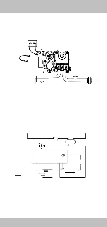
Standing Pilot
Gas flow to the pilot burner is controlled by a safety valve which is manually operated and held in by current generated from a thermocouple placed in the pilot flame. When the thermostat calls for heat the main valve is energized.
Electrical Cut Out (E.C.O.) Switch or
Supplementary Limit in appliance
ECO Terminals (2) |
Power Unit |
|
Jumper
NOTE: If appliance does not |
ON |
have E.C.O. Switch |
T |
or supplementary limit, |
PILO |
OFF |
|
jumper E.C.O. terminals |
|
TH, TH-TR to Thermostat
TH |
TR |
TH TR |
|
PILOT |
TH-TR, TR to Transformer |
ADJ. |
W |
R |
24 VAC |
Line |
Hot |
|
|
|
|
|
Thermostat |
Transformer |
|
||
Wiring for 36C03 (24 VAC) with E.C.O.
Proven Pilot
The thermostat calls for heat and simultaneously energizes the pilot valve and the Proven Pilot control. Sparking from the ignition electrode to the pilot burner ignites the gas at the pilot burner.
Flame is sensed by the flame detection circuit which energizes the main valve. Main burner gas is ignited and sparking ceases once a pilot flame is detected.
HOT |
LINEVOLTAGE |
NEUTRAL |
LIMIT 120VAC
|
W |
|
R |
|
|
|
|
COMMON (“C”) |
|
|
|
THERMOSTAT |
|
|
|
|
25 VAC |
|
|
|
|
|
|
|
|
H.V. LEAD |
T |
P |
M |
M |
P |
T |
G |
F |
IGNITION |
N |
||||||||
H |
V |
V |
V |
V |
R |
D |
P |
ELECTRODE |
|
|
|
|
|
|
|
|
(PILOT) |
|
|
|
C |
|
|
|
|
|
|
|
|
P |
|
|
|
|
SENSE |
LINEVOLTAGE |
|
|
M |
|
|
|
|
|
|
|
|
|
|
|
ELECTRODE |
||
LOWVOLTAGE |
|
|
|
|
|
|
|
|
Typical Wiring for Proven/Intermittent Pilot System
Gas Valve Cross Reference 9
 Loading...