


Vission 20/20 micro-controller
Operation and service manual

Table of Contents
Section Title |
Section Number |
How To Use This Manual.................................................................................................................... |
TOC-8 |
Section 1 • Operational Flow Charts |
|
Requirements to Start Compressor ................................................................................................... |
1-1 |
Critical Compressor Run Logic at Compressor Start........................................................................... |
1-1 |
Compressor Amperage Load Limiting ............................................................................................... |
1-1 |
Figure 1-1. Operational Flow Charts .................................................................................................. |
1-1 |
High Discharge Pressure Load Limiting............................................................................................. |
1-1 |
Suction Pressure Override Load Limit During Temperature Control ................................................... |
1-2 |
Section 2 • Installation Recommendations |
|
Proper Wiring Sizing ......................................................................................................................... |
2-1 |
Voltage Source ................................................................................................................................. |
2-1 |
Figure 2-1. Vission 20/20 with Individual Transformer ....................................................................... |
2-1 |
Figure 2-2. EMI and Vission 20/20 ..................................................................................................... |
2-1 |
Grounding ........................................................................................................................................ |
2-2 |
Mixing Voltages ................................................................................................................................ |
2-2 |
DC signals ......................................................................................................................................... |
2-2 |
Figure 2-3. Ground Wiring ................................................................................................................ |
2-2 |
Figure 2-4. Mixed Voltage Wiring...................................................................................................... |
2-2 |
Wiring Methods................................................................................................................................ |
2-3 |
Figure 2-5. Correct Transformer Wiring Method ............................................................................... |
2-3 |
Figure 2-6. Incorrect Transformer Wiring Method ............................................................................. |
2-3 |
Best Practices.................................................................................................................................... |
2-4 |
Section 3 • Hardware Architecture |
|
Overview .......................................................................................................................................... |
3-1 |
Figure 3-1. Hardware Architecture Overview .................................................................................... |
3-1 |
Digital Input/Output (I/O)................................................................................................................. |
3-2 |
Table 3-1. Digital I/O ......................................................................................................................... |
3-3 |
Analog Inputs ................................................................................................................................... |
3-4 |
Table 3-2. Analog Inputs.................................................................................................................... |
3-5 |
Analog Outputs ................................................................................................................................ |
3-6 |
Digital & Analog I/O Boards Layout.................................................................................................... |
3-6 |
Table 3-3. Analog Outputs................................................................................................................. |
3-7 |
Figure 3-2. Digital I/O Board Layout................................................................................................... |
3-7 |
Digital Outpout Boards ..................................................................................................................... |
3-8 |
Figure 3-3. Digital Output Board Layout ............................................................................................ |
3-8 |
Digital Input Boards .......................................................................................................................... |
3-9 |
Figure 3-4. Digital Input Board Layout ............................................................................................... |
3-9 |
Digital In-Out Boards ........................................................................................................................ |
3-10 |
Figure 3-5. Digital Input-Output Board Layout................................................................................... |
3-10 |
Analog Input Boards ......................................................................................................................... |
3-11 |
Figure 3-6. Analog Input Board Layout .............................................................................................. |
3-11 |
Analog Input Jumper Tables .............................................................................................................. |
3-12 |
Table 3-4. Analog Input Jumper Tables.............................................................................................. |
3-12 |
Analog Output Boards ...................................................................................................................... |
3-14 |
Figure 3-6. Analog Output Board Layout ........................................................................................... |
3-14 |
Vission 20/20 • Operation and Service Manual •Vilter/Emerson • 35391SC 1.8.5153 |
TOC - 1 |

Table of Contents |
|
|
|
Section Title |
Section Number |
Section 4 • Main Screen |
|
Overview .......................................................................................................................................... |
4-1 |
Figure 4-1. Digital I/O Board Layout................................................................................................... |
4-1 |
Top Status Bar................................................................................................................................... |
4-2 |
Figure 4-2. Top Status Bar ................................................................................................................. |
4-2 |
Parameter Bar................................................................................................................................... |
4-3 |
Figure 4-3. Parameter Bar ................................................................................................................. |
4-3 |
Figure 4-4. Unit Start Pop-Up Window .............................................................................................. |
4-4 |
Bottom Status Bar............................................................................................................................. |
4-5 |
Figure 4-5. Bottom Status Bar ........................................................................................................... |
4-5 |
Splash Screen.................................................................................................................................... |
4-6 |
Figure 4-6. Splash Screen .................................................................................................................. |
4-6 |
Section 5 • Menu Screen |
|
Overview .......................................................................................................................................... |
5-1 |
Navigation Buttons ........................................................................................................................... |
5-1 |
Figure 5-1. Menu Screen ................................................................................................................... |
5-2 |
Section 6 • Compressor Control |
|
Overview .......................................................................................................................................... |
6-1 |
Pulse Proportional Control................................................................................................................ |
6-1 |
Figure 6-1. Compressor Control Screen ............................................................................................. |
6-1 |
Auto-Cycle ........................................................................................................................................ |
6-2 |
Figure 6-2. Proportional Band & Setpoint .......................................................................................... |
6-2 |
Variable Frequency Drive (VFD)......................................................................................................... |
6-3 |
Figure 6-3. VFD One-Step Control Method ........................................................................................ |
6-3 |
Figure 6-4. VFD Two-Step Control Method ........................................................................................ |
6-3 |
Pumpdown Control........................................................................................................................... |
6-4 |
Pulldown Control .............................................................................................................................. |
6-5 |
Control Mode.................................................................................................................................... |
6-6 |
Stop load & Force unload .................................................................................................................. |
6-6 |
Capacity Slide Triggered Outputs...................................................................................................... |
6-6 |
Volume Slide Position Offset ............................................................................................................. |
6-6 |
Soft Load .......................................................................................................................................... |
6-6 |
Load Anticipating.............................................................................................................................. |
6-7 |
Oil Control ........................................................................................................................................ |
6-7 |
Liquid Injection ................................................................................................................................. |
6-7 |
Section 7 • Alarms and Trips |
|
Overview .......................................................................................................................................... |
7-1 |
Alarms and Trips Setpoints................................................................................................................ |
7-1 |
Figure 7-1. Alarms and Trips Screen................................................................................................... |
7-1 |
Compressor Inhibits.......................................................................................................................... |
7-3 |
Safety Failure Messages .................................................................................................................... |
7-3 |
Section 8 • Timers |
|
Overview .......................................................................................................................................... |
8-1 |
Timer Setpoints ................................................................................................................................ |
8-1 |
Figure 8-1. Timers Screen.................................................................................................................. |
8-1 |
Section 9 • Compressor Scheduling |
|
Overview .......................................................................................................................................... |
9-1 |
Scheduling Setpoint.......................................................................................................................... |
9-1 |
Figure 9-1. Compressor Scheduling Screen ....................................................................................... |
9-1 |
TOC - 2 |
Vission 20/20 • Operation and Service Manual •Vilter/Emerson • 35391SC 1.8.5153 |

Table of Contents
Section Title |
Section Number |
Section 10 • Compressor Sequencing |
|
Overview .......................................................................................................................................... |
10-1 |
Pressure Control Setpoints................................................................................................................ |
10-1 |
Figure 10-1. Compressor Sequencing Screen .................................................................................... |
10-1 |
Section 11 • Condenser Control |
|
Overview .......................................................................................................................................... |
11-1 |
Condenser Control Setpoint.............................................................................................................. |
11-1 |
Figure 11-1. Condenser Control Screen ............................................................................................. |
11-1 |
Step Control...................................................................................................................................... |
11-2 |
Figure 11-2. Step Control Screen....................................................................................................... |
11-3 |
VFD Settings ..................................................................................................................................... |
11-3 |
Section 12 • Service Options |
|
Overview .......................................................................................................................................... |
12-1 |
Digital Outputs ................................................................................................................................. |
12-1 |
Figure 12-1. Service Options Screen.................................................................................................. |
12-1 |
Analog Outputs ................................................................................................................................ |
12-2 |
Section 13 • Instruments Calibration |
|
Overview .......................................................................................................................................... |
13-1 |
Pressure and Temperature Inputs...................................................................................................... |
13-1 |
Figure 13-1. Instruments Calibration Screen ..................................................................................... |
13-1 |
Motor Current................................................................................................................................... |
13-2 |
Remote Capacity .............................................................................................................................. |
13-2 |
Analog Inputs ................................................................................................................................... |
13-2 |
Section 14 • Slide Calibration |
|
Overview .......................................................................................................................................... |
14-1 |
Capacity Slide Valve Potentiometer................................................................................................... |
14-1 |
Figure 14-1. Slide Calibration Screen................................................................................................. |
14-1 |
Volume Slide Valve Potentiometer .................................................................................................... |
14-2 |
Slide Valve Operation........................................................................................................................ |
14-2 |
Slide Valve Actuator Calibration for Optical Style Motors................................................................... |
14-2 |
Figure 14-2. Photochopper ............................................................................................................... |
14-3 |
Command Shaft Rotation.................................................................................................................. |
14-4 |
Table 14-1. Command Shaft Rotation Required By Actuator .............................................................. |
14-4 |
Slide Valve Troubleshooting Guide .................................................................................................... |
14-5 |
Table 14-2. Slide Valve Troubleshooting Guide .................................................................................. |
14-5 |
Slide Valve Actuator Troubleshooting Guide Blink Code .................................................................... |
14-7 |
Table 14-3. LED Blink Codes and Troubleshooting Guide.................................................................... |
14-7 |
Section 15 • Trend Chart |
|
Overview .......................................................................................................................................... |
15-1 |
Chart Operation................................................................................................................................ |
15-1 |
Figure 15-1. Trend Chart Screen ........................................................................................................ |
15-1 |
Trend Data Storage ........................................................................................................................... |
15-2 |
Setup................................................................................................................................................ |
15-3 |
Figure 15-2. Trend Setup Screen........................................................................................................ |
15-3 |
Vission 20/20 • Operation and Service Manual •Vilter/Emerson • 35391SC 1.8.5153 |
TOC - 3 |

Table of Contents |
|
|
|
Section Title |
Section Number |
Section 16 • Event List |
|
Overview .......................................................................................................................................... |
16-1 |
Event list Columns............................................................................................................................. |
16-1 |
Figure 16-1. Event List Screen............................................................................................................ |
16-1 |
Section 17 • Input / Output |
|
Overview .......................................................................................................................................... |
17-1 |
Figure 17-1. Input/Output Screen ..................................................................................................... |
17-1 |
Section 18 • Auxiliary Input / Output |
|
Overview .......................................................................................................................................... |
18-1 |
Digital Inputs .................................................................................................................................... |
18-1 |
Figure 18-1. Auxiliary Input/Output Screen ....................................................................................... |
18-1 |
Digital Outputs ................................................................................................................................. |
18-2 |
Analog Inputs ................................................................................................................................... |
18-2 |
Analog Outputs ................................................................................................................................ |
18-3 |
Control ............................................................................................................................................. |
18-3 |
Section 19 • Configuration |
|
Overview .......................................................................................................................................... |
19-1 |
Units................................................................................................................................................. |
19-1 |
Time & Date...................................................................................................................................... |
19-1 |
Figure 19-1. Configuration Screen - Page 1........................................................................................ |
19-1 |
Communications .............................................................................................................................. |
19-2 |
Touchscreen ..................................................................................................................................... |
19-2 |
Anti-Recycle...................................................................................................................................... |
19-2 |
Restart On Power Failure................................................................................................................... |
19-3 |
Compressor Sequencing ................................................................................................................... |
19-3 |
Language.......................................................................................................................................... |
19-3 |
Model & Refrigerant.......................................................................................................................... |
19-3 |
Figure 19-2. Configuration Screen - Page 2........................................................................................ |
19-4 |
Compressor Control.......................................................................................................................... |
19-4 |
Optional Function Selection.............................................................................................................. |
19-4 |
Condenser Control............................................................................................................................ |
19-5 |
Oil Pump........................................................................................................................................... |
19-5 |
Oil Cooling........................................................................................................................................ |
19-5 |
Motor Current Device ....................................................................................................................... |
19-5 |
Figure 19-3. Configuration Screen - Page 3........................................................................................ |
19-6 |
Digital Inputs .................................................................................................................................... |
19-6 |
Analog Inputs ................................................................................................................................... |
19-7 |
Figure 19-4. Configuration Screen - Page 4........................................................................................ |
19-7 |
Figure 19-5. Configuration Screen - Page 5........................................................................................ |
19-8 |
Analog Outputs ................................................................................................................................ |
19-8 |
Digital Outputs ................................................................................................................................. |
19-8 |
I/O Configuration.............................................................................................................................. |
19-9 |
Figure 19-6. Configuration Screen - Page 6........................................................................................ |
19-9 |
TOC - 4 |
Vission 20/20 • Operation and Service Manual •Vilter/Emerson • 35391SC 1.8.5153 |

Table of Contents
Section Title |
Section Number |
Section 20 • Data Backup |
|
Overview .......................................................................................................................................... |
20-1 |
Save / Load........................................................................................................................................ |
20-1 |
Figure 20-1. Data Backup Screen - Save/Load .................................................................................... |
20-1 |
Migrate............................................................................................................................................. |
20-3 |
Factory Reset .................................................................................................................................... |
20-3 |
Figure 20-2. Data Backup Screen - Migrate and Factory Reset............................................................ |
20-3 |
Section 21 • Maintenance |
|
Overview .......................................................................................................................................... |
21-1 |
Checklist........................................................................................................................................... |
21-1 |
Figure 21-1. Maintenance Screen ...................................................................................................... |
21-1 |
Notes................................................................................................................................................ |
21-2 |
Log ................................................................................................................................................... |
21-2 |
Chart ................................................................................................................................................ |
21-2 |
Section 22 • User Access |
|
Overview .......................................................................................................................................... |
22-1 |
Apply ................................................................................................................................................ |
22-1 |
Figure 22-1. User Access Screen - Login ............................................................................................. |
22-1 |
Figure 22-2. User Access Screen - Manage Accounts.......................................................................... |
22-2 |
Login ................................................................................................................................................ |
22-2 |
Manage Accounts ............................................................................................................................. |
22-2 |
Screen Security Levels....................................................................................................................... |
22-3 |
Table 22-1. Security Access Levels ..................................................................................................... |
22-3 |
Section 23 • Help Screen |
|
Overview .......................................................................................................................................... |
23-1 |
Screen Features:................................................................................................................................ |
23-1 |
Figure 23-1. Help Screen ................................................................................................................... |
23-1 |
Figure 23-2. Version Pop-Up Screen .................................................................................................. |
23-2 |
Section 24 • Twin Screw Control |
|
Overview .......................................................................................................................................... |
24-1 |
Setup................................................................................................................................................ |
24-1 |
Figure 24-1. Twin Screw Control Screen ............................................................................................ |
24-1 |
Operation ......................................................................................................................................... |
24-2 |
Section 25 • Cool Compression Control |
|
Overview .......................................................................................................................................... |
25-1 |
Setup................................................................................................................................................ |
25-1 |
Figure 25-1. Cool Compression Control Screen.................................................................................. |
25-1 |
Figure 25-2. Cool Compression Control Functions Screen.................................................................. |
25-2 |
Control Functions ............................................................................................................................. |
25-2 |
Operational Differences from Single Screw ....................................................................................... |
25-3 |
Vission 20/20 • Operation and Service Manual •Vilter/Emerson • 35391SC 1.8.5153 |
TOC - 5 |

List of Tables and Figures
Table/Figure |
Page Number |
Table 3-1. Digital I/O ......................................................................................................................... |
3-3 |
Table 3-2. Analog Inputs.................................................................................................................... |
3-5 |
Table 3-3. Analog Outputs................................................................................................................. |
3-7 |
Table 3-4. Analog Input Jumper Tables.............................................................................................. |
3-12 |
Table 14-1. Command Shaft Rotation Required By Actuator .............................................................. |
14-4 |
Table 14-2. Slide Valve Troubleshooting Guide .................................................................................. |
14-5 |
Table 14-3. LED Blink Codes and Troubleshooting Guide.................................................................... |
14-7 |
Table 22-1. Security Access Levels ..................................................................................................... |
22-3 |
Figure 1-1. Operational Flow Charts .................................................................................................. |
1-1 |
Figure 2-1. Vission 20/20 with Individual Transformer ....................................................................... |
2-1 |
Figure 2-2. EMI and Vission 20/20 ..................................................................................................... |
2-1 |
Figure 2-3. Ground Wiring ................................................................................................................ |
2-2 |
Figure 2-4. Mixed Voltage Wiring...................................................................................................... |
2-2 |
Figure 2-5. Correct Transformer Wiring Method ............................................................................... |
2-3 |
Figure 2-6. Incorrect Transformer Wiring Method ............................................................................. |
2-3 |
Figure 3-1. Hardware Architecture Overview .................................................................................... |
3-1 |
Figure 3-2. Digital I/O Board Layout................................................................................................... |
3-7 |
Figure 3-3. Digital Output Board Layout ............................................................................................ |
3-8 |
Figure 3-4. Digital Input Board Layout ............................................................................................... |
3-9 |
Figure 3-5. Digital Input-Output Board Layout................................................................................... |
3-10 |
Figure 3-6. Analog Input Board Layout .............................................................................................. |
3-11 |
Figure 3-7. Analog Output Board Layout ........................................................................................... |
3-14 |
Figure 4-1. Digital I/O Board Layout................................................................................................... |
4-1 |
Figure 4-2. Top Status Bar ................................................................................................................. |
4-2 |
Figure 4-3. Parameter Bar ................................................................................................................. |
4-3 |
Figure 4-4. Unit Start Pop-Up Window .............................................................................................. |
4-4 |
Figure 4-5. Bottom Status Bar ........................................................................................................... |
4-5 |
Figure 4-6. Splash Screen .................................................................................................................. |
4-6 |
Figure 5-1. Menu Screen ................................................................................................................... |
5-2 |
Figure 6-1. Compressor Control Screen ............................................................................................. |
6-1 |
Figure 6-2. Proportional Band & Setpoint .......................................................................................... |
6-2 |
Figure 6-3. VFD One-Step Control Method ........................................................................................ |
6-3 |
Figure 6-4. VFD Two-Step Control Method ........................................................................................ |
6-3 |
Figure 7-1. Alarms and Trips Screen................................................................................................... |
7-1 |
Figure 8-1. Timers Screen.................................................................................................................. |
8-1 |
Figure 9-1. Compressor Scheduling Screen ....................................................................................... |
9-1 |
Figure 10-1. Compressor Sequencing Screen .................................................................................... |
10-1 |
Figure 11-1. Condenser Control Screen ............................................................................................. |
11-1 |
Figure 11-2. Step Control Screen....................................................................................................... |
11-3 |
Figure 12-1. Service Options Screen.................................................................................................. |
12-1 |
Figure 13-1. Instruments Calibration Screen ..................................................................................... |
13-1 |
Figure 14-1. Slide Calibration Screen................................................................................................. |
14-1 |
Figure 14-2. Photochopper ............................................................................................................... |
14-3 |
Figure 15-1. Trend Chart Screen ........................................................................................................ |
15-1 |
Figure 15-2. Trend Setup Screen........................................................................................................ |
15-3 |
Figure 16-1. Event List Screen............................................................................................................ |
16-1 |
Figure 17-1. Input/Output Screen ..................................................................................................... |
17-1 |
Figure 18-1. Auxiliary Input/Output Screen ....................................................................................... |
18-1 |
Figure 19-1. Configuration Screen - Page 1........................................................................................ |
19-1 |
Figure 19-2. Configuration Screen - Page 2........................................................................................ |
19-4 |
Figure 19-3. Configuration Screen - Page 3........................................................................................ |
19-6 |
TOC - 6 |
Vission 20/20 • Operation and Service Manual •Vilter/Emerson • 35391SC 1.8.5153 |

List of Tables and Figures
Table/Figure |
Page Number |
Figure 19-4. Configuration Screen - Page 4........................................................................................ |
19-7 |
Figure 19-5. Configuration Screen - Page 5........................................................................................ |
19-8 |
Figure 19-6. Configuration Screen - Page 6........................................................................................ |
19-9 |
Figure 20-1. Data Backup Screen - Save/Load .................................................................................... |
20-1 |
Figure 20-2. Data Backup Screen - Migrate and Factory Reset............................................................ |
20-3 |
Figure 21-1. Maintenance Screen ...................................................................................................... |
21-1 |
Figure 22-1. User Access Screen - Login ............................................................................................. |
22-1 |
Figure 22-2. User Access Screen - Manage Accounts.......................................................................... |
22-2 |
Figure 23-1. Help Screen ................................................................................................................... |
23-1 |
Figure 23-2. Version Pop-Up Screen .................................................................................................. |
23-2 |
Figure 24-1. Twin Screw Control Screen ............................................................................................ |
24-1 |
Figure 25-1. Cool Compression Control Screen.................................................................................. |
25-1 |
Figure 25-2. Cool Compression Control Functions Screen.................................................................. |
25-2 |
END OF TOC
Vission 20/20 • Operation and Service Manual •Vilter/Emerson • 35391SC 1.8.5153 |
TOC - 7 |

How to Use This Manual
This manual contains instructions for the Vission 20/20 Operation & Service Manual. It has been divided into 25 sections.
Section 1: Operational Flow Charts
Section 2: Installation Recommendations
Section 3: Hardware Architecture
Section 4: Main Screen
Section 5: Menu Screen
Section 6: Compressor Control
Section 7: Alarms & Trips
Section 8: Timers
Section 9: Compressor Scheduling
Section 10: Compressor Sequencing
Section 11: Condensor Control
Section 12: Service Options
Section 13: Instruments Calibration
Section 14: Slide Calibration
Section 15: Trend Chart
Section 16: Event List
Section 17: Input/Output
Section 18: Auxiliary Input/Output
Section 19: Configuration
Section 20: Data Backup
Section 21: Maintenance
Section 22: User Access
Section 23: Help Screen
Section 24: Twin Screw Control
Section 25: Cool Compression Control
It is highly recommended that the manual be reviewed prior to servicing the Vission 20/20 system parts.
Figures and tables are included to illustrate key concepts.
Safety precautions are shown throughout the manual. They are defined as the following:
WARNING - Warning statements are shown when there are hazardous situations, if not avoided, will result in serious injury or death.
CAUTION - Caution statements are shown when there are potentially hazardous situations, if not avoided, will result in damage to equipment.
NOTE - Notes are shown when there are addtional information pertaining to the instructions explained.
NOTICE - Notices are shown when there are important information that can help avoid system failure.
For additional information pertaining to the Vission 20/20, refer to www.Vission2020.net/documents. Information that can be found on the site are:
•Manuals
•Release Advisories
•Application Notes
•Videos
TOC - 8 |
Vission 20/20 • Operation and Service Manual •Vilter/Emerson • 35391SC 1.8.5153 |
Section 1 • Operational Flow Charts
Requirements to Start Compressor
Volume and Capacity slides are less than 5%
Oil Separator Temp |
Filter Diff Press < |
>Oil Sep Start Trip |
Start Filter Diff Trip |
Setpt |
Setpt |
Oil Pump On: Prelub Oil Press is > Prelub Oil
Press Reset Setpt for “Min Compressor Prelub Timer” Start Compressor setting (typically 5 seconds)
Critical Compressor Run Logic at Compressor Start
Start
Compressor
|
Is |
|
|
|
|
“Oil Press |
|
|
Run Oil Press> |
|
|
|
|
|
|||
|
|
|
|
Bypass at Comp |
|
|||
Prelub Oil Press |
|
|
|
|
|
|||
|
|
|
|
|
|
|||
|
Yes |
|
|
Start” timer |
|
|||
Reset setpt? |
|
|
|
|
||||
|
|
|
|
expires (60 sec |
|
|||
(Default 5 PSI) |
|
|
|
|
|
|||
|
|
|
|
after start) |
|
|||
|
|
|
|
|
|
|
|
|
|
|
|
|
|
|
|
|
|
|
|
|
|
|
|
|
|
|
|
No |
|
|
|
|
|
|
|
Run Oil Press Failure
|
Yes |
|
“Filter Diff Press Safety |
Is Filter Diff > |
|
Hi Filter Diff Press Run |
||
Changeover” timer expires |
||
Trip Setpt |
||
(60 sec after start) |
||
for 5 seconds |
||
|
|
Is |
|
|
Run Oil Press> |
|
Yes |
Run Oil Press |
|
Reset setpt? |
||
|
||
|
(Default 40 PSI) |
|
|
No |
|
|
Run Oil Press Failure |
|
|
|
Oil Separator Temp |
|
|
|
Is |
|
|
|
|
|
|
|
Safety Changeover |
|
|
|
Oil Sep Temp > Lo |
|
|
|
|
No |
|
|
|
Yes |
|
|
Yes |
|
Run |
||
|
|
Timer expires (5 min |
|
|
Oil Sep Run Reset |
|
|
||||
|
|
|
|
|
|
|
|
|
|
||
|
|
|
|
|
|
|
|
|
|
||
|
|
|
after start) |
|
|
|
setpt? |
|
|
|
|
|
|
|
|
|
|
|
|
|
|
|
|
No
Yes
Lo Run Oil Sep Temp Failure
Run Filter Diff Press Failure
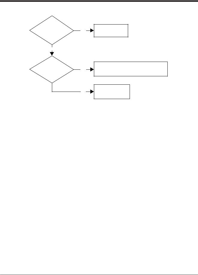
Compressor Amperage Load Limiting
|
Is |
|
|
|
|
|
|
Motor Amps > |
|
|
|
|
Capacity Increase |
||
|
Yes |
|
|
||||
FLA (ON) |
|
|
|
Disabled |
|||
|
|
|
|
||||
Setpt? |
|
|
|
|
|
||
|
|
|
|
|
|||
|
|
|
|
|
|
|
|
|
No |
|
|
|
|
|
|
Is
Motor Amps >
Capacity Decrease
FLA (OFF)
Yes until Amps < FLA x
Setpt?
1.0625
No |
Normal Loading and |
|
Unloading |
||
|
High Discharge Pressure Load Limiting
|
Is |
|
|
|
|
|
||
Dsch Press > |
|
|
|
|
Capacity Increase |
|||
|
Yes |
|
|
|||||
Cutin (ON) |
|
|
|
Disabled |
||||
|
|
|
|
|||||
Setpt? |
|
|
|
|
|
|||
|
|
|
|
|
||||
|
|
|
|
|
|
|
|
|
|
|
|
|
|
|
|
|
|
|
No |
|
|
|
|
|
|
|
Is
Dsch Press >
Capacity Decrease until
Cutout (OFF)
Yes Dsch Press < ON Setpt x
Setpt?
1.0625
No
Normal Loading and
Unloading
Figure 1-1. Operational Flow Charts (1 of 2)
Vission 20/20 • Operation and Service Manual •Vilter/Emerson • 35391SC 1.8.5153 |
1 – 1 |
Section 1 • Operational Flow Charts
Suction Pressure Override Load Limit During Temperature Control
Is
Suction Press <
Suct Press Cap
Dec OFF
Setpt?
No
Is
Suction Press <
Suct Press Cap
Dec ON
Setpt?
Yes
Capacity Increase
Disabled
Yes |
Decrease compressor capacity until Suction |
|
Press > Suction Press Cap Decrease ON setpoint. |
||
|
No
Normal Loading and
Unloading
Figure 1-1. Operational Flow Charts (2 of 2)
1 – 2 |
Vission 20/20 • Operation and Service Manual •Vilter/Emerson • 35391SC 1.8.5153 |
Section 2 • Installation Recommendations
Proper Wiring Sizing
•Always size wire gauges as specified by the National Electrical Code (NEC) for electronic control devices.
•For improved noise immunity, install one size larger wire gauge than the NEC requirement to assure ample current-carrying capability.
•Never under size wire gauges.
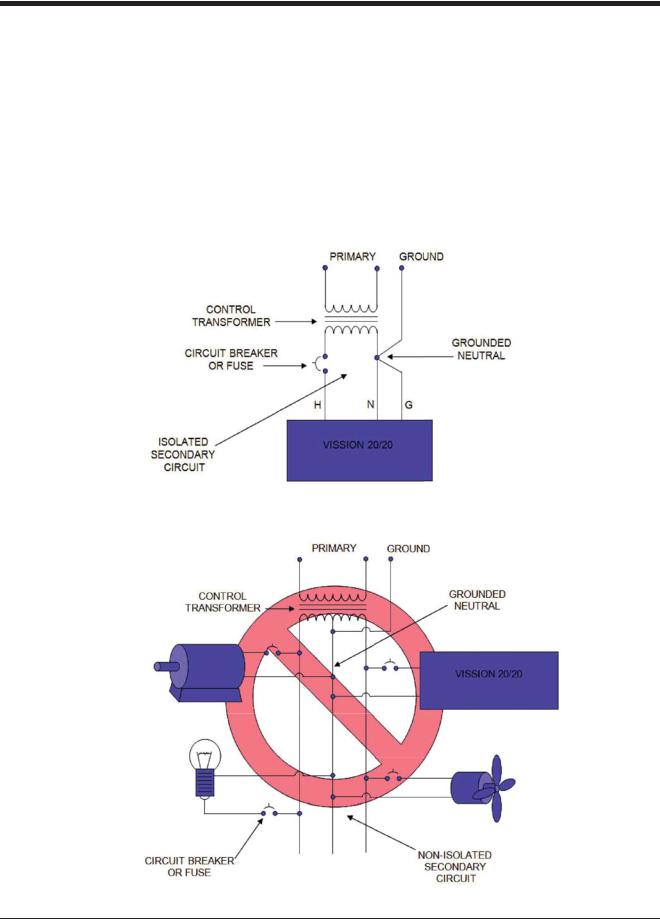
Voltage Source
• Transformers block a large percentage of
Electro-Magnetic Interference (EMI). The Vilter Vission 20/20 should be isolated with its own control transformer for the most reliable operation, see Figure 2-1. Vission 20/20 with Individual Transformer.
•Connecting the Vilter Vission 20/20 to breaker panels and central control transformers exposes the Vission 20/20 to large amounts of EMI emitted from the other devices connected to the secondary terminals of the transformer. This practice should be avoided if possible, see Figure 2-2. EMI and Vission 20/20.
Figure 2-1. Vission 20/20 with Individual Transformer
Figure 2-2. EMI and Vission 20/20
Vission 20/20 • Operation and Service Manual •Vilter/Emerson • 35391SC 1.8.5153 |
2 – 1 |
Section 2 • Installation Recommendations
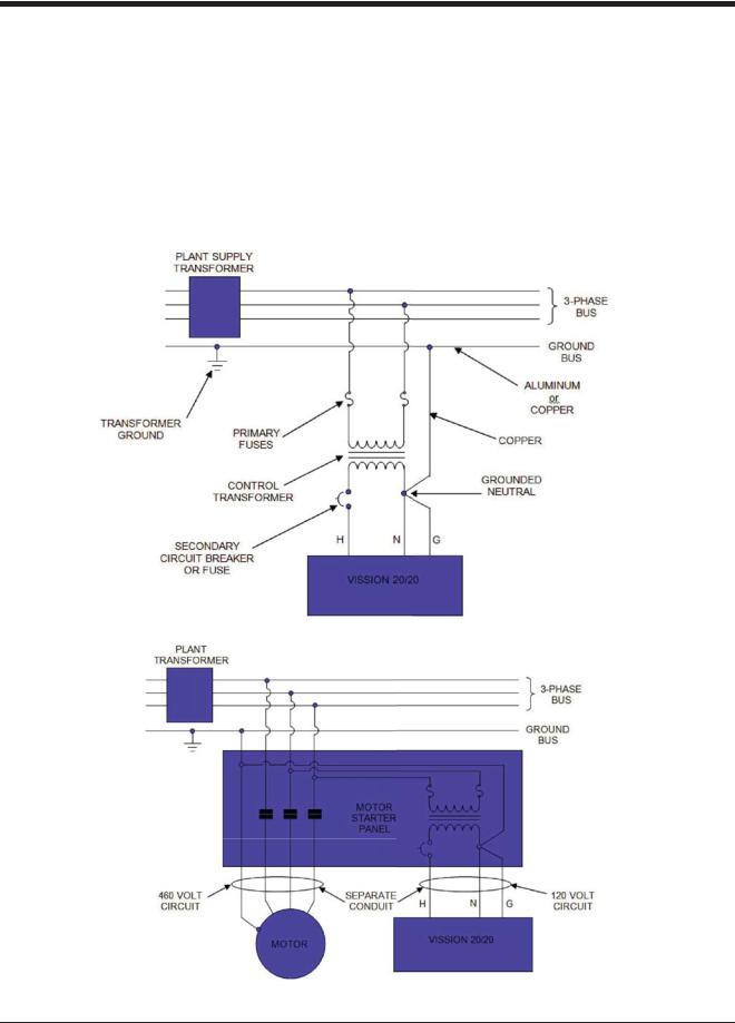
Grounding
•Continuous grounds must be run from the utility ground to the Vission 20/20, see Figure 2-3. Grounding.
•Grounds must be copper or aluminum wire.
•Never use conduit grounds.
Each voltage level must be run in separate conduit:
•460 VAC
•230 VAC
•120 VAC
•24 VAC
Mixing Voltages
•Separate different voltages from each other and separate AC from DC, see Figure 2-4. Mixed Voltage Wiring.
DC signals
•If your installation site has wire-ways or conduit trays, dividers must be installed between the different voltages.
Figure 2-3. Ground Wiring
Figure 2-4. Mixed Voltage Wiring
2 – 2 |
Vission 20/20 • Operation and Service Manual •Vilter/Emerson • 35391SC 1.8.5153 |
Section 2 • Installation Recommendations
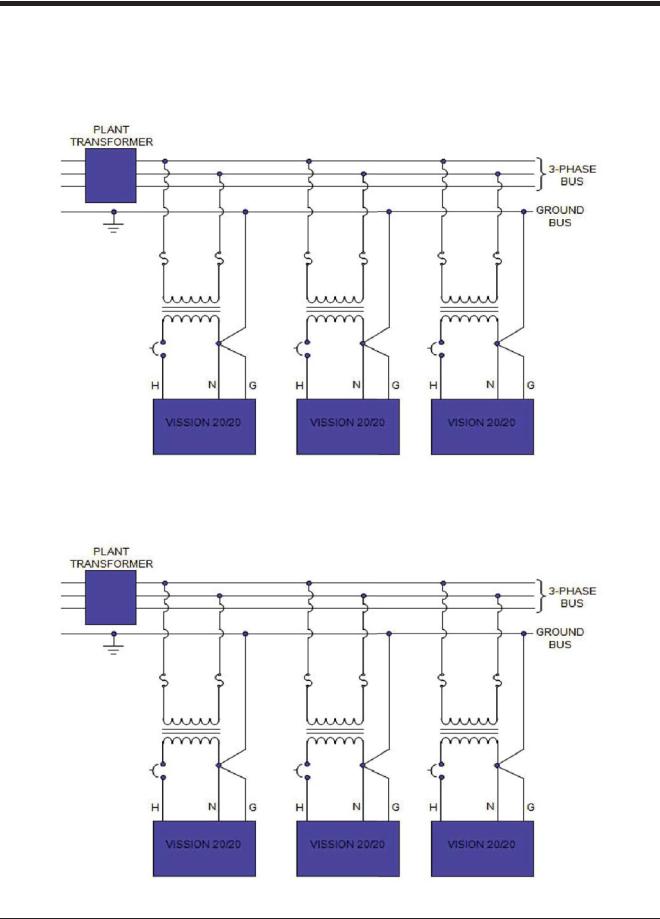
Wiring Methods
•Each Vission 20/20 panel should have its own individual control transformer, see Figure 2-5. Correct Transformer Wiring Method and Figure 2-6. Incorrect Transformer Wiring Method.
Figure 2-5. Correct Transformer Wiring Method
Figure 2-6. Incorrect Transformer Wiring Method
Vission 20/20 • Operation and Service Manual •Vilter/Emerson • 35391SC 1.8.5153 |
2 – 3 |

Section 2 • Installation Recommendations
Best Practices
• Do:
•Keep AC wires away from circuit boards.
•Always run conduit into the bottom or sides of an enclosure.
•If the conduit must be placed in the top of an enclosure, use a water-tight conduit fitting to keep water from entering the enclosure.
•The Vission 20/20 is supplied with prepunched conduit holes. Use them!
•Don’t:
•Don’t run wires through the Vission 20/20 enclosure that are not related to the compressor control.
•Don’t add relays, timers, transformers, etc. in the Vission 20/20 enclosure without first checking with Vilter.
•Don’t run conduit into the top of an enclosure.
•Don’t run refrigerant tubing inside the enclosure.
•Don’t drill metal enclosures without taking proper precautions to protect circuit boards from damage.
2 – 4 |
Vission 20/20 • Operation and Service Manual •Vilter/Emerson • 35391SC 1.8.5153 |
Section 3 • Hardware Architecture
Overview
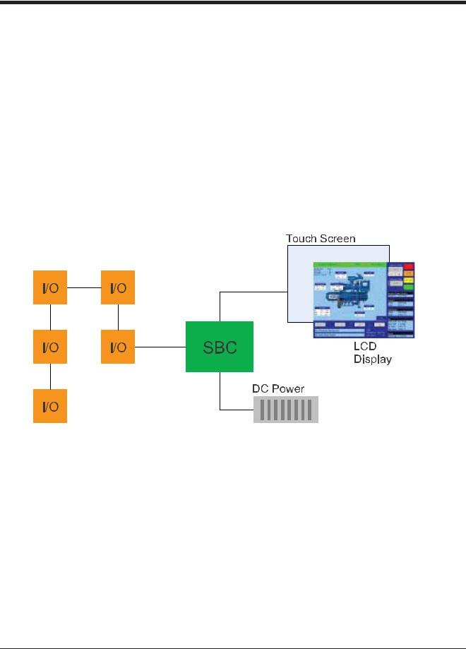
The Vission 20/20 control panel utilizes X-86 PC technology with a Linux operating system. For hardware architecture, see Figure 3-1 Hardware Architecture Overview.
The Vission 20/20 has the following attributes:
•Low power, Industrial rated X-86 CPU.
•15” XGA, high resolution LCD display. (Outdoor viewable LCD optional).
•8-wire touch screen operator interface.
•Flexible and expandable I/O.
•NEMA-4 enclosure (NEMA-4X optional).
•Industrial temperature range design.
Figure 3-1. Hardware Architecture Overview
Vission 20/20 • Operation and Service Manual •Vilter/Emerson • 35391SC 1.8.5153 |
3 – 1 |

Section 3 • Hardware Architecture
Digital Input/Output (I/O)
Refer to Table 2-1. Digital I/O.
Compressor Start Output:
•When the Vission 20/20 signals the compressor to start, this output is energized. When the Vission 20/20 signals the compressor to stop, this output is de-energized.
Oil Pump Start Output:
•When the Vission 20/20 signals the oil pump to start, this output is energized. When the Vission 20/20 signals the oil pump to stop, this output is de-energized.
Capacity Increase Output:
•This output is only active when the compressor is running. When the Vission 20/20 determines that the compressor should increase capacity by moving the slide valve to a higher percentage, this output is energized. Once the slide valve reaches 100%, this output will not energize.
Capacity Decrease Output:
•This output is only active when the compressor is running. When the Vission 20/20 determines that the compressor should decrease capacity by moving the slide valve to a lower percentage, this output is energized. Once the slide valve reaches 0%, this output will not energize.
Volume Increase Output:
•This output is only active when the compressor is running. When the Vission 20/20 determines that the compressor should increase Volume Index (VI) by moving the volume slide to a higher percentage, this output is energized. Once the volume slide reaches 100%, this output will not energize.
Volume Decrease Output:
•This output is only active when the compressor is running. When the Vission 20/20 determines that the compressor should decrease Volume Index (VI) by moving the volume slide to a lower percentage, this output is energized. Once the volume slide reaches 0%, this output will not energize.
Oil Sump Heater Output:
•This output is active and energized when the oil separator temperature is lower than the oil separator temperature setpoint. It is de-energized when the oil separator temperature is higher than the oil separator temperature setpoint.
Trip Output:
•This output is energized when the system has no Trips. If a trip is issued, the output de-energizes and stays de-energized until the trip condition is cleared.
Slide Valve Setpoint #1 Output (Economizer):
•Normally used for an economizer solenoid, but could be used for other devices. When the compressor slide valve percentage is equal to or greater than “slide valve set-point #1”, the output is energized. When the compressor slide valve percentage is less than “slide valve set-point #1”, the output is de-energized.
Slide Valve Setpoint #2 Output (Hot Gas):
•Normally used for a hot gas solenoid, but could be used for other devices. When the compressor slide valve percentage is equal to or greater than “slide valve set-point #2”, the output is energized. When the compressor slide valve percentage is less than “slide valve set-point #2”, the output is de-energized.
Alarm Output:
•This output is energized when the system has no alarms. If an alarm is issued, the output de-energizes and stays de-energized until the alarm condition is cleared.
Unused:
•This output has no current function. Liquid Injection #1 Output:
•If the compressor has liquid injection oil cooling, this output is active. When the compressor is running and the discharge temperature is above the oil separator temperature override setpoint and the oil separator temperature is above the override setpoint, then the output is energized. The output is de-energized when the discharge temperature falls below the “on” setpoint minus the solenoid differential.
Liquid Injection #2 Output:
• Not Defined
Remote Enabled Output:
•This output is energized when the Vission 20/20 panel is enabled for remote control. The compressor can be running or stopped, but is available to the remote system. If the compressor has an alarm or is placed into the manual stop position, this output is de-energized.
Shunt Trip:
• Not defined.
Comp Motor Starter Auxiliary Contact:
•This input looks for a feedback signal from the compressor starter, confirming that the compressor starter is energized.
3 – 2 |
Vission 20/20 • Operation and Service Manual •Vilter/Emerson • 35391SC 1.8.5153 |

Section 3 • Hardware Architecture
Table 3-1. Digital I/O (1 of 2)
Board |
I/O # |
Description |
Type |
1 |
1 |
Compressor Start |
OUTPUT |
|
|
|
|
1 |
2 |
Oil Pump Start |
OUTPUT |
|
|
|
|
1 |
3 |
Capacity Increase |
OUTPUT |
|
|
|
|
1 |
4 |
Capacity Decrease |
OUTPUT |
|
|
|
|
1 |
5 |
Volume Increase |
OUTPUT |
|
|
|
|
1 |
6 |
Volume Decrease |
OUTPUT |
|
|
|
|
1 |
7 |
Oil Separator Heater |
OUTPUT |
|
|
|
|
2 |
8 |
Trip indicator (ON=Normal) |
OUTPUT |
|
|
|
|
2 |
9 |
Slide Valve Set point #1 (Economizer) |
OUTPUT |
|
|
|
|
2 |
10 |
Slide Valve Set point #2 (Hot Gas) |
OUTPUT |
|
|
|
|
2 |
11 |
Alarm |
OUTPUT |
|
|
|
|
2 |
12 |
Unused |
OUTPUT |
|
|
|
|
2 |
13 |
Liquid Injection #1 |
OUTPUT |
|
|
|
|
2 |
14 |
Liquid Injection #2 |
OUTPUT |
|
|
|
|
2 |
15 |
Remote Enabled |
OUTPUT |
|
|
|
|
2 |
16 |
Shunt Trip |
OUTPUT |
|
|
|
|
3 |
17 |
Comp Motor Starter Auxiliary Contact |
INPUT |
|
|
|
|
3 |
18 |
High Level Shutdown |
INPUT |
|
|
|
|
3 |
19 |
Oil Level Float Switch #1 |
INPUT |
|
|
|
|
3 |
20 |
Oil Level Float Switch #2 |
INPUT |
|
|
|
|
3 |
21 |
Remote Setpoint #1/#2 Selection |
INPUT |
|
|
|
|
3 |
22 |
Remote Start/Stop |
INPUT |
|
|
|
|
3 |
23 |
Remote Capacity Increase |
INPUT |
|
|
|
|
3 |
24 |
Remote Capacity Decrease |
INPUT |
|
|
|
|
4 |
25 |
Condenser Step #1 |
OUTPUT |
|
|
|
|
4 |
26 |
Condenser Step #2 |
OUTPUT |
|
|
|
|
4 |
27 |
Condenser Step #3 |
OUTPUT |
|
|
|
|
4 |
28 |
Condenser Step #4 |
OUTPUT |
|
|
|
|
4 |
29 |
Auxiliary Input #1 |
INPUT |
|
|
|
|
4 |
30 |
Auxiliary Input #2 |
INPUT |
|
|
|
|
4 |
31 |
Auxiliary Input #3 |
INPUT |
|
|
|
|
4 |
32 |
Auxiliary Input #4 |
INPUT |
|
|
|
|
Vission 20/20 • Operation and Service Manual •Vilter/Emerson • 35391SC 1.8.5153 |
3 – 3 |

Section 3 • Hardware Architecture
High Level Shutdown Input:
•This input must be energized in order for the compressor to operate. If de-energized, the compressor will shut down and issue a high level trip.
Oil Level Float Switch #1 Input:
•Used for Cool Compression. Oil Level Float Switch #2 Input:
•Used for Cool Compression. Remote Select #1/#2 Input:
•This input enables or disables remote I/O control. Energizing this input enables the Remote Capacity Increase and Remote Capacity Decrease inputs.
Remote Start/Stop Input:
•If the compressor is enabled for remote I/O control, this input is enabled. Energizing this input will issue a start for the compressor as long as it is available to run. De-energizing this input stops the compressor.
Remote Capacity Increase Input:
NOTE
The scan interval on the remote increase and decrease inputs is approximately ONE SECOND. Please take that into account when developing a control scheme using the remote increase and remote decrease inputs for compressor control.
•If the compressor is enabled for remote I/O control, this input is enabled. Operational only when the compressor is running. Energizing this input will increase the slide valve position.
•The slide valve will continuously increase as long as this input is energized. The slide valve will not increase when this input is de-energized.
Remote Capacity Decrease Input:
•Operational only when the compressor is running. This input is enabled if the compressor is enabled for remote I/O control. Energizing this input will decrease the slide valve position. The slide valve will continuously decrease as long as this input is energized. The slide valve will not decrease when this input is de-energized.
Condenser Step #1 Output:
•This output is enabled when condenser control option is selected. A condenser fan or pump will be turned on or off by this output.
Condenser Step #2 Output:
•This output is enabled when condenser control option is selected. A condenser fan or pump will be turned on or off by this output.
Condenser Step #3 Output:
•This output is enabled when condenser control option is selected. A condenser fan or pump will be turned on or off by this output.
Condenser Step #4 Output:
•This output is enabled when condenser control option is selected. A condenser fan or pump will be turned on or off by this output.
Auxiliary Inputs #1 - #8:
•Optional inputs that can be configured as an alarm or trip. Typically connected to external switched devices.
Auxiliary Outputs #1 - #4:
•Optional inputs that can be configured as an alarm or trip. Typically connected to external switched devices.
Analog Inputs
Refer to Table 2-2. Analog Inputs.
Motor Current:
•Default is a 0-5 Amp current transformer (CT). Current transformer ratio is set in the calibration screen.
Suction Pressure:
•Default signal is 4-20mA. Suction pressure transducer range and calibration is set in the calibration screen.
Discharge Pressure
•Default signal is 4-20mA. Discharge pressure transducer range and calibration is set in the calibration screen.
Oil Filter Inlet Pressure:
•Default signal is 4-20mA. Oil filter pressure transducer range and calibration is set in the calibration screen.
Oil Manifold Pressure:
•Default signal is 4-20mA. Oil manifold pressure transducer range and calibration is set in the calibration screen.
Economizer Pressure:
•Default signal is 4-20mA. Economizer pressure transducer range and calibration is set in the calibration screen.
Slide Valve Position:
•Reads the 0-5 volt signal back from the slide position motor actuator to indicate current slide valve position.
3 – 4 |
Vission 20/20 • Operation and Service Manual •Vilter/Emerson • 35391SC 1.8.5153 |
Section 3 • Hardware Architecture
Table 3-1. Digital I/O (2 of 2)
Board |
I/O # |
Description |
Type |
5 |
33 |
Auxiliary Output #1 |
OUTPUT |
|
|
|
|
5 |
34 |
Auxiliary Output #2 |
OUTPUT |
|
|
|
|
5 |
35 |
Auxiliary Output #3 |
OUTPUT |
|
|
|
|
5 |
36 |
Auxiliary Output #4 |
OUTPUT |
|
|
|
|
5 |
37 |
Auxiliary Input #5 |
INPUT |
|
|
|
|
5 |
38 |
Auxiliary Input #6 |
INPUT |
|
|
|
|
5 |
39 |
Auxiliary Input #7 |
INPUT |
|
|
|
|
5 |
40 |
Auxiliary Input #8 |
INPUT |
|
|
|
|
Table 3-2. Analog Inputs (1 of 2)
|
Board |
I/O # |
Description |
Type |
|
|
6 |
1 |
Motor Current |
4-20 mA, 0-5A |
|
|
|
|
|
|
|
|
6 |
2 |
Suction Pressure |
0-5V, 1-5 V, 0-10V, 4-20 mA |
|
|
|
|
|
|
|
|
6 |
3 |
Discharge Pressure |
0-5V, 1-5 V, 0-10V, 4-20 mA |
|
|
|
|
|
|
|
|
6 |
4 |
Oil Filter Inlet Pressure |
0-5V, 1-5 V, 0-10V, 4-20 mA |
|
|
|
|
|
|
|
|
6 |
5 |
Oil Manifold Pressure |
0-5V, 1-5 V, 0-10V, 4-20 mA |
|
|
|
|
|
|
|
|
6 |
6 |
Economizer Pressure |
0-5V, 1-5 V, 0-10V, 4-20 mA |
|
|
|
|
|
|
|
|
6 |
7 |
% Slide Valve Position |
0-5V, 4-20 mA, Potentiometer |
|
|
|
|
|
|
|
|
6 |
8 |
% Volume Position |
0-5V, 4-20 mA, Potentiometer |
|
|
|
|
|
|
|
|
7 |
9 |
Suction Temperature |
4-20 mA, RTD, ICTD |
|
|
|
|
|
|
|
|
7 |
10 |
Discharge Temperature |
4-20 mA, RTD, ICTD |
|
|
|
|
|
|
|
|
7 |
11 |
Oil Separator Temperature |
4-20 mA, RTD, ICTD |
|
|
|
|
|
|
|
|
7 |
12 |
Oil Manifold Temperature |
4-20 mA, RTD, ICTD |
|
|
|
|
|
|
|
|
7 |
13 |
Process Temperature |
4-20 mA, RTD, ICTD |
|
|
|
|
|
|
|
|
7 |
14 |
Chiller Inlet Temperature |
4-20 mA, RTD, ICTD |
|
|
|
|
|
|
|
|
7 |
15 |
Condenser Pressure |
0-5V, 1-5 V, 0-10V, 4-20 mA, RTD, ICTD |
|
|
|
|
|
|
|
|
7 |
16 |
Remote Caphold Setpoint |
0-5V, 4-20 mA, RTD, ICTD |
|
|
|
|
|
|
|
|
8 |
17 |
Auxiliary #1 |
0-5V, 1-5 V, 0-10V, 4-20 mA, RTD, ICTD |
|
|
|
|
|
|
|
|
8 |
18 |
Auxiliary #2 |
0-5V, 1-5 V, 0-10V, 4-20 mA, RTD, ICTD |
|
|
|
|
|
|
|
|
8 |
19 |
Auxiliary #3 |
0-5V, 1-5 V, 0-10V, 4-20 mA, RTD, ICTD |
|
|
|
|
|
|
|
|
8 |
20 |
Auxiliary #4 |
0-5V, 1-5 V, 0-10V, 4-20 mA, RTD, ICTD |
|
|
|
|
|
|
|
|
8 |
21 |
Auxiliary #5 |
0-5V, 1-5 V, 0-10V, 4-20 mA, RTD, ICTD |
|
|
|
|
|
|
|
|
8 |
22 |
Auxiliary #6 |
0-5V, 1-5 V, 0-10V, 4-20 mA, RTD, ICTD |
|
|
|
|
|
|
|
|
8 |
23 |
Auxiliary #7 |
0-5V, 1-5 V, 0-10V, 4-20 mA, RTD, ICTD |
|
|
|
|
|
|
|
|
8 |
24 |
Auxiliary #8 |
0-5V, 1-5 V, 0-10V, 4-20 mA, RTD, ICTD |
|
|
|
|
|
|
|
|
9 |
25 |
Auxiliary #9 |
0-5V, 1-5 V, 0-10V, 4-20 mA, RTD, ICTD |
|
|
|
|
|
|
|
|
9 |
26 |
Auxiliary #10 |
0-5V, 1-5 V, 0-10V, 4-20 mA, RTD, ICTD |
|
|
|
|
|
|
|
|
9 |
27 |
Auxiliary #11 |
0-5V, 1-5 V, 0-10V, 4-20 mA, RTD, ICTD |
|
|
|
|
|
|
|
|
|
|
|
|
|
Vission 20/20 • Operation and Service Manual •Vilter/Emerson • 35391SC 1.8.5153 |
3 – 5 |

Section 3 • Hardware Architecture
Volume Position:
•Reads the 0-5 volt signal back from the slide volume motor actuator to indicate current volume position.
Suction Temperature:
•Default signal is RTD. Suction temperature calibration is set in the calibration screen.
Discharge Temperature:
•Default signal is RTD. Discharge temperature calibration is set in the calibration screen.
Oil Separator Temperature:
•Default signal is RTD. Oil separator temperature calibration is set in the calibration screen.
Oil Manifold Temperature:
•Default signal is RTD. Oil manifold temperature calibration is set in the calibration screen.
Process Temperature:
•Default signal is 4-20mA. Process temperature calibration and range are set in the calibration screen.
Chiller Inlet Temperature:
•Default signal is 4-20mA. Measures separator level. Chiller Inlet Temperature calibration and range are set in the calibration screen.
Condenser Pressure:
•Default signal is 4-20mA. Condenser pressure transducer range and calibration is set in the calibration screen.
Remote Caphold:
•Default signal is 4-20mA. Active in “Direct I/O” mode. Adjusts the capacity of the compressor from 0-100%, proportional to the 4-20mA signal.
Auxiliary #1 - #16:
•Flexible analog inputs that can be configured to control, alarm or trip.
Analog Outputs:
Refer to Table 2-3. Analog Outputs.
Compressor VFD:
•4-20mA output to control compressor motor speed with a Variable Frequency Drive (VFD).
Condenser VFD:
•4-20mA output to control one condenser fan which is interleaved between the remaining condenser steps for smoother control.
% Slide Valve Position:
•4-20mA signal that transmits the slide valve position for remote monitoring.
Motorized Valve (V+):
•For a cool compression compressor, this 4-20mA signal controls a motorized valve to regulate the liquid refrigerant level in the oil separator. For a liquid injection application on a standard single screw, this 4-20mA signal controls a motorized valve to regulate the liquid refrigerant injected into the compressor for oil cooling purposes.
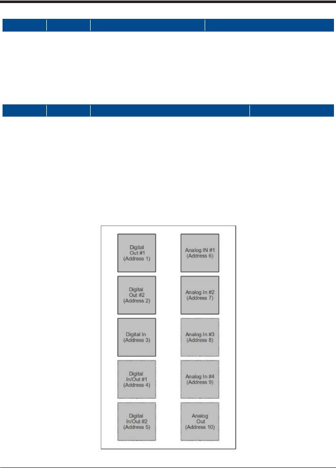
Digital & Analog I/O Boards Layout
It is important to install the boards in the proper layout. For the correct digital and analog input/output (I/O) board layout, see Figure 3-2. Digital I/O Board Layout.
Dipswitches
•Each board has a dipswitch which sets its communications address so that it can communicate with the CPU board. The dipswitch settings must be correct or the I/O will not function.
Jumpers
•Jumpers are required on the analog boards to configure them for the type of sensors used. The jumper table for the analog board shows the optional jumper configurations for sensors other than the default Vilter standard. If a different sensor is to be used, the jumpers on the analog board need to be changed. In addition, the configuration for this sensor must be changed in the Instrument Calibration screen. The following illustrations show the Vilter default configurations for the Vission 20/20.
3 – 6 |
Vission 20/20 • Operation and Service Manual •Vilter/Emerson • 35391SC 1.8.5153 |
Section 3 • Hardware Architecture
Table 3-2. Analog Inputs (2 of 2)
Board |
I/O # |
Description |
Type |
9 |
28 |
Auxiliary #12 |
0-5V, 1-5 V, 0-10V, 4-20 mA, RTD, ICTD |
|
|
|
|
9 |
29 |
Auxiliary #13 |
0-5V, 1-5 V, 0-10V, 4-20 mA, RTD, ICTD |
|
|
|
|
9 |
30 |
Auxiliary #14 |
0-5V, 1-5 V, 0-10V, 4-20 mA, RTD, ICTD |
|
|
|
|
9 |
31 |
Auxiliary #15 |
0-5V, 1-5 V, 0-10V, 4-20 mA, RTD, ICTD |
|
|
|
|
9 |
32 |
Auxiliary #16 |
0-5V, 1-5 V, 0-10V, 4-20 mA, RTD, ICTD |
|
|
|
|
Table 3-3. Analog Outputs
Board |
I/O # |
Description |
Type |
|
10 |
1 |
Compressor VFD |
4-20 mA |
|
|
|
|
|
|
10 |
2 |
Condenser VFD |
4-20 mA |
|
|
|
|
|
|
10 |
3 |
% Slide Valve Position |
4-20 mA |
|
|
|
|
|
|
10 |
4 |
Motorized Valve (Cool Compression or Liquid |
4-20 mA |
|
Injection), V+ |
||||
|
|
|
||
10 |
5 |
Spare / Unused |
4-20 mA |
|
|
|
|
|
|
10 |
6 |
Spare / Unused |
4-20 mA |
|
|
|
|
|
|
10 |
7 |
Spare / Unused |
4-20 mA |
|
|
|
|
|
|
10 |
8 |
Spare / Unused |
4-20 mA |
|
|
|
|
|
Figure 3-2. Digital I/O Board Layout
Vission 20/20 • Operation and Service Manual •Vilter/Emerson • 35391SC 1.8.5153 |
3 – 7 |
Section 3 • Hardware Architecture
Digital Output Boards
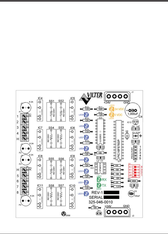
The digital output board convert signals generated by the Vission 20/20 program into 120Vac signals that can be energize or signal other devices. All the signals are digital in that the only two states available or either on or off. See board layout, Figure 3-3. Digital Output Board Layout.
Signal LED’s:
•Marked in the diagram below in Blue. These LED’s indicated when a 120Vac output is being produced.
Voltage LED’s:
•Marked in the diagram below in Orange. These LED’s indicated the correct voltage of both the 5Vdc and 24Vdc power sources.
Communication LED’s:
•Marked in the diagram below in Green. These LED’s Show the active communications between the digital output board and the Vission 20/20 CPU board.
Address Dipswitches:
•Marked in the diagram below in Red. These dipswitches are used to assign each board its address position. The addresses are binary and therefor the address of a digital output board will either be address as 1 (0001) or 2 (0010).
Figure 3-3. Digital Output Board Layout
3 – 8 |
Vission 20/20 • Operation and Service Manual •Vilter/Emerson • 35391SC 1.8.5153 |
Section 3 • Hardware Architecture
Digital Input Boards
The digital input board convert 120Vdc signals from external devices to signal for the Vission 20/20 program. All the signals are digital in that the only two states available or either on or off. See board layout, Figure 3-4. Digital Input Board Layout.
Signal LEDs:
•Marked in the diagram below in light Blue. These LEDs indicated when a 120Vac input is detected.
Voltage LEDs:
•Marked in the diagram below in Orange. These LEDs indicated the correct voltage of both the 5Vdc and 24Vdc power sources.
Communication LEDs:
•Marked in the diagram below in Green. These LEDs Show the active communications between the digital output board and the Vission 20/20 CPU board.
Address Dipswitches:
•Marked in the diagram below in Red. These dipswitches are used to assign each board its address position. The addresses are binary and therefor the address of a digital input board can only be addressed as 3 (0011).
Figure 3-4. Digital Input Board Layout
Vission 20/20 • Operation and Service Manual •Vilter/Emerson • 35391SC 1.8.5153 |
3 – 9 |
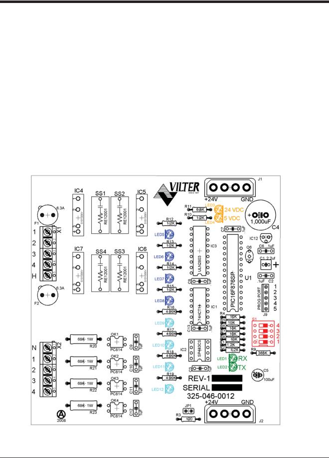
Section 3 • Hardware Architecture
Digital In-Out Boards
The digital input - output board convert signals generated by the Vission 20/20 program into 120Vac signals as well as detect external 120Vac inputs to signal the Vission 20/20 program.
All the signals are digital in that the only two states available or either on or off. See board layout, Figure 3-5. Digital Input-Output Board Layout.
Signal LEDs:
•Marked in the diagram below in Blue or outputs and light blue for inputs. These LEDs indicate when a 120Vac output is being produced or a 120Vac signal is detected.
Voltage LEDs:
•Marked in the diagram below in Orange. These LEDs indicated the correct voltage of both the 5Vdc and 24Vdc power sources.
Communication LEDs:
•Marked in the diagram below in Green. These LEDs show the active communications between the digital output board and the Vission 20/20 CPU board.
Address Dipswitches:
•Marked in the diagram below in Red. These dipswitches are used to assign each board its address position. The addresses are binary and therefore the address of a digital output board will either be address as 4 (0100) or 5 (0101).
Figure 3-5. Digital Input-Output Board Layout
3 – 10 |
Vission 20/20 • Operation and Service Manual •Vilter/Emerson • 35391SC 1.8.5153 |

Section 3 • Hardware Architecture
Analog Input Boards
The analog input board convert varying DC signals into a signal that can interpreted by the Vission 20/20 program. The signals are considered analog because the input DC signal can vary from the minimum value to the maximum value. See board layout, Figure 3-6. Analog Input Board Layout.
Configuration Jumpers:
•Marked in the diagram below in Purple. The jumpers allow the operator to configure the signal type and range for incoming analog signals. For the correct jumper setting for a giving application, see Table 2-4. Analog Input Jumper Tables.
Voltage LEDs:
•Marked in the diagram below in Orange. These LEDs indicated the correct voltage of both the 5Vdc and 24Vdc power sources.
Communication LEDs:
•Marked in the diagram below in Green. These LEDs Show the active communications between the digital output board and the Vission 20/20 CPU board.
Address Dipswitches:
•Marked in the diagram below in Red. These dipswitches are used to assign each board its address position. The addresses are binary and therefore the address of a digital output board will be address as 6 (0110), 7 (0111), 8 (1000) or 9 (1001).
Figure 3-6. Analog Input Board Layout
Vission 20/20 • Operation and Service Manual •Vilter/Emerson • 35391SC 1.8.5153 |
3 – 11 |

Section 3 • Hardware Architecture
Analog Input Jumper Tables
The following tables are used to configure each channel of the analog input board signal type and range desired by the operator, see Table 2-4. Analog Input Jumper Tables.
Table 3-4. Analog Input Jumper Tables
CHANNEL 1 |
SIGNAL |
JP-1 |
JP-2 |
JP-3 |
JP-27 JP-35 |
|
|
|
|
|
|
|
|
Analog Input 1-A* |
0-5 AMP |
OUT |
OUT |
OUT |
OUT |
IN |
|
|
|
|
|
|
|
Analog input 1-B** |
0-5 VOLT |
OUT |
OUT |
OUT |
OUT |
OUT |
|
|
|
|
|
|
|
|
1-5 VOLT |
OUT |
OUT |
OUT |
OUT |
OUT |
|
|
|
|
|
|
|
|
0-10 VOLT |
OUT |
OUT |
IN |
OUT |
OUT |
|
|
|
|
|
|
|
|
4-20 mA |
IN |
OUT |
OUT |
OUT |
OUT |
|
|
|
|
|
|
|
|
ICTD |
OUT |
IN |
OUT |
OUT |
OUT |
|
|
|
|
|
|
|
|
RTD |
OUT |
OUT |
OUT |
IN |
OUT |
|
|
|
|
|
|
|
*Use Analog Input 1-A when 0-5 AMP secondary current transformers are installed in the motor starter. **Use Analog Input 1-B when current transformers are installed in the motor starter.
|
CHANNEL 2 |
SIGNAL |
JP-4 |
JP-5 |
JP-6 |
JP-28 |
|
|
|
|
|
|
|
|
|
|
Analog Input 2 |
0-5 VOLT |
OUT |
OUT |
OUT |
OUT |
|
|
|
|
|
|
|
|
|
|
|
1-5 VOLT |
OUT |
OUT |
OUT |
OUT |
|
|
|
|
|
|
|
|
|
|
|
0-10 VOLT |
OUT |
OUT |
IN |
OUT |
|
|
|
|
|
|
|
|
|
|
|
4-20 mA |
IN |
OUT |
OUT |
OUT |
|
|
|
|
|
|
|
|
|
|
|
ICTD |
OUT |
IN |
OUT |
OUT |
|
|
|
|
|
|
|
|
|
|
|
RTD |
OUT |
OUT |
OUT |
IN |
|
|
|
|
|
|
|
|
|
|
|
|
|
|
|
|
|
|
CHANNEL 3 |
SIGNAL |
JP-7 |
JP-8 |
JP-9 |
JP-29 |
|
|
|
|
|
|
|
|
|
|
Analog Input 3 |
0-5 VOLT |
OUT |
OUT |
OUT |
OUT |
|
|
|
|
|
|
|
|
|
|
|
1-5 VOLT |
OUT |
OUT |
OUT |
OUT |
|
|
|
|
|
|
|
|
|
|
|
0-10 VOLT |
OUT |
OUT |
IN |
OUT |
|
|
|
|
|
|
|
|
|
|
|
4-20 mA |
IN |
OUT |
OUT |
OUT |
|
|
|
|
|
|
|
|
|
|
|
ICTD |
OUT |
IN |
OUT |
OUT |
|
|
|
|
|
|
|
|
|
|
|
RTD |
OUT |
OUT |
OUT |
IN |
|
|
|
|
|
|
|
|
|
|
|
|
|
|
|
|
|
|
CHANNEL 4 |
SIGNAL |
JP-10 |
JP-11 |
JP-12 JP-30 |
|
|
|
|
|
|
|
|
|
|
|
Analog Input 4 |
0-5 VOLT |
OUT |
OUT |
OUT |
OUT |
|
|
|
|
|
|
|
|
|
|
|
1-5 VOLT |
OUT |
OUT |
OUT |
OUT |
|
|
|
|
|
|
|
|
|
|
|
0-10 VOLT |
OUT |
OUT |
IN |
OUT |
|
|
|
|
|
|
|
|
|
|
|
4-20 mA |
IN |
OUT |
OUT |
OUT |
|
|
|
|
|
|
|
|
|
|
|
ICTD |
OUT |
IN |
OUT |
OUT |
|
|
|
|
|
|
|
|
|
|
|
RTD |
OUT |
OUT |
OUT |
IN |
|
|
|
|
|
|
|
|
|
|
|
|
|
|
|
|
|
3 – 12 |
Vission 20/20 • Operation and Service Manual •Vilter/Emerson • 35391SC 1.8.5153 |

Section 3 • Hardware Architecture
Table 3-4. Analog Input Jumper Tables (Continued)
CHANNEL 5 |
SIGNAL |
JP-13 |
JP-14 |
JP-15 JP-31 |
|
|
|
|
|
|
|
Analog Input 5 |
0-5 VOLT |
OUT |
OUT |
OUT |
OUT |
|
|
|
|
|
|
|
1-5 VOLT |
OUT |
OUT |
OUT |
OUT |
|
|
|
|
|
|
|
0-10 VOLT |
OUT |
OUT |
IN |
OUT |
|
|
|
|
|
|
|
4-20 mA |
IN |
OUT |
OUT |
OUT |
|
ICTD |
OUT |
IN |
OUT |
OUT |
|
RTD |
OUT |
OUT |
OUT |
IN |
CHANNEL 6 |
SIGNAL |
JP-16 |
JP-17 |
JP-18 JP-32 |
|
|
|
|
|
|
|
Analog Input 6 |
0-5 VOLT |
OUT |
OUT |
OUT |
OUT |
|
|
|
|
|
|
|
1-5 VOLT |
OUT |
OUT |
OUT |
OUT |
|
|
|
|
|
|
|
0-10 VOLT |
OUT |
OUT |
IN |
OUT |
|
|
|
|
|
|
|
4-20 mA |
IN |
OUT |
OUT |
OUT |
|
|
|
|
|
|
|
ICTD |
OUT |
IN |
OUT |
OUT |
|
|
|
|
|
|
|
RTD |
OUT |
OUT |
OUT |
IN |
|
|
|
|
|
|
CHANNEL 7 |
SIGNAL |
JP-19 |
JP-20 |
JP-21 JP-33 |
JP-25 |
|
|
|
|
|
|
|
|
Analog Input 7 |
0-5 VOLT |
OUT |
OUT |
OUT |
OUT |
2 |
|
|
|
|
|
|
|
|
1-5 VOLT |
OUT |
OUT |
OUT |
OUT |
2 |
|
|
|
|
|
|
|
|
0-10 VOLT |
OUT |
OUT |
IN |
OUT |
2 |
|
|
|
|
|
|
|
|
4-20 mA |
IN |
OUT |
OUT |
OUT |
2 |
|
|
|
|
|
|
|
|
ICTD |
OUT |
IN |
OUT |
OUT |
2 |
|
|
|
|
|
|
|
|
RTD |
OUT |
OUT |
OUT |
IN |
2 |
|
|
|
|
|
|
|
|
ACTUATOR |
OUT |
OUT |
OUT |
OUT |
1 |
|
|
|
|
|
|
|
|
POTENTIOMETER |
OUT |
OUT |
OUT |
OUT |
3 |
|
|
|
|
|
|
|
CHANNEL 8 |
SIGNAL |
JP-22 |
JP-23 |
JP-24 JP-34 |
JP-26 |
|
|
|
|
|
|
|
|
Analog Input 8 |
0-5 VOLT |
OUT |
OUT |
OUT |
OUT |
2 |
|
|
|
|
|
|
|
|
1-5 VOLT |
OUT |
OUT |
OUT |
OUT |
2 |
|
|
|
|
|
|
|
|
0-10 VOLT |
OUT |
OUT |
IN |
OUT |
2 |
|
|
|
|
|
|
|
|
4-20 mA |
IN |
OUT |
OUT |
OUT |
2 |
|
|
|
|
|
|
|
|
ICTD |
OUT |
IN |
OUT |
OUT |
2 |
|
|
|
|
|
|
|
|
RTD |
OUT |
OUT |
OUT |
IN |
2 |
|
|
|
|
|
|
|
|
ACTUATOR |
OUT |
OUT |
OUT |
OUT |
1 |
|
|
|
|
|
|
|
|
POTENTIOMETER |
OUT |
OUT |
OUT |
OUT |
3 |
|
|
|
|
|
|
|
Vission 20/20 • Operation and Service Manual •Vilter/Emerson • 35391SC 1.8.5153 |
3 – 13 |
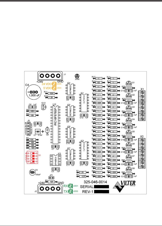
Section 3 • Hardware Architecture
Analog Output Boards
The Analog Output board convert signals form the Vission 20/20 program into a current ranging from 4mA to 20mA, see Figure 3-7. Analog Output Board Layout.
Voltage LEDs:
•Marked in the diagram below in Orange. These LEDs indicated the correct voltage of both the 5Vdc and 24Vdc power sources.
Communication LED’s:
•Marked in the diagram below in Green. These LEDs show the active communications between the digital output board and the Vission 20/20 CPU board.
Address Dipswitches:
•Marked in the diagram below in Red. These dipswitches are used to assign each board its address position. The addresses are binary and therefore the address of a digital output board will only be addressed as 10 (1010).
Figure 3-7. Analog Output Board Layout
3 – 14 |
Vission 20/20 • Operation and Service Manual •Vilter/Emerson • 35391SC 1.8.5153 |
 Loading...