


 Loading...
Reference Manual
00809-0100-4102, Rev AA
May 2013
Rosemount 2051 Wireless Pressure Transmitters
Pressure, Level, and Flow Solutions with WirelessHART™ Protocol

Reference Manual
00809-0100-4102, Rev AA
Rosemount 2051 Wireless Pressure, Flow,
and Level Solutions
Read this manual before working with the product. For personal and system safety, and for optimum product performance, make sure you thoroughly understand the contents before installing, using, or maintaining this product.
For technical assistance, contacts are listed below:
Customer Central
Technical support, quoting, and order-related questions. United States - 1-800-999-9307 (7:00 am to 7:00 pm CST) Asia Pacific65 777 8211
Europe/ Middle East/ Africa - 49 (8153) 9390
North American Response Center Equipment service needs.
1-800-654-7768 (24 hours—includes Canada)
Outside of these areas, contact your local Emerson Process Management representative.
The products described in this document are NOT designed for nuclear-qualified applications. Using non-nuclear qualified products in applications that require nuclear-qualified hardware or products may cause inaccurate readings.
For information on Emerson Process Management nuclear-qualified products, contact your local Rosemount Sales Representative.
i

Reference Manual
00809-0100-4102, Rev AA
Explosions could result in death or serious injury:
Installation of this transmitter in an explosive environment must be in accordance with the appropriate local, national, and international standards, codes, and practices. Please review the approvals section of the 2051 reference manual for any restrictions associated with a safe installation.
Before connecting a HART-based communicator in an explosive atmosphere, make sure the instruments in the loop are installed in accordance with intrinsically safe or non-incendive field wiring practices.
This device complies with Part 15 of the FCC Rules. Operation is subject to the following conditions.
This device may not cause harmful interference. This device must accept any interference received, including interference that may cause undesired operation.
This device must be installed to ensure a minimum antenna separation distance of 8 in. (20cm) from all persons.
Process leaks may cause harm or result in death.
To avoid process leaks, only use the o-ring designed to seal with the corresponding flange adapter.
Electrical shock can result in death or serious injury.
Avoid contact with the leads and the terminals. High voltage that may be present on leads can cause electrical shock.
The Rosemount 2051 and all other wireless devices should be installed only after the Smart Wireless Gateway has been installed and is functioning properly. Wireless devices should also be powered up in order of proximity from the Smart Wireless Gateway, beginning with the closest. This will result in a simpler and faster network installation.
ii

Reference Manual
00809-0100-4102, Rev AA
Shipping considerations for wireless products (Lithium Batteries: Green Power Module, model number 701PGNKF):
The unit was shipped to you without the Power Module installed. Please remove the Power Module from the unit prior to shipping.
Each power module contains one “D” size primary lithium-thionyl chloride battery. Primary lithium batteries are regulated in transportation by the U.S. Department of Transportation, and are also covered by IATA (International Air Transport Association), ICAO (International Civil Aviation Organization), and ARD (European Ground Transportation of Dangerous Goods). It is the responsibility of the shipper to ensure compliance with these or any other local requirements. Please consult current regulations and requirements before shipping.
The power module with the wireless unit contains one “D” size primary lithium-thionyl chloride battery (Green Power Module, model number 701PGNKF). Each battery contains approximately 5.0 grams of lithium. Under normal conditions, the battery materials are self-contained and are not reactive as long as the battery and the pack integrity are maintained. Care should be taken to prevent thermal, electrical or mechanical damage. Contacts should be protected to prevent premature discharge.
Battery hazards remain when cells are discharged.
Power modules should be stored in a clean and dry area. For maximum battery life, storage temperature should not exceed 30 °C (86 °F).
The Power Module may be replaced in a hazardous area. The Power Module has surface resistivity greater than one gigaohm and must be properly installed in the wireless device enclosure. Care must be taken during transportation to and from the point of installation to prevent electrostatic charge build-up.
Using the Rosemount 2051 Wireless Pressure Transmitter in a manner other than what is specified by the manufacturer may impair the protection provided by the equipment.
iii

Reference Manual
00809-0100-4102, Rev AA
iv
Reference Manual |
Table of Contents |
00809-0100-4102, Rev AA |
May 2013 |
|
|
Contents
Section 1: Introduction
1.1 Using this manual. . . . . . . . . . . . . . . . . . . . . . . . . . . . . . . . . . . . . . . . . . . . . . . . . . . . . . .1 1.2 Models covered . . . . . . . . . . . . . . . . . . . . . . . . . . . . . . . . . . . . . . . . . . . . . . . . . . . . . . . .1 1.2.1 Rosemount 2051C Coplanar™ Pressure Transmitter . . . . . . . . . . . . . . . . . . .1 1.2.2 Rosemount 2051T in-line Pressure Transmitter . . . . . . . . . . . . . . . . . . . . . . .1 1.2.3 Rosemount 2051L Level Transmitter . . . . . . . . . . . . . . . . . . . . . . . . . . . . . . . .2 1.2.4 Rosemount 2051CF Flowmeters . . . . . . . . . . . . . . . . . . . . . . . . . . . . . . . . . . . .2 1.3 WirelessHART installation flowchart . . . . . . . . . . . . . . . . . . . . . . . . . . . . . . . . . . . . . .3 1.4 Transmitter overview . . . . . . . . . . . . . . . . . . . . . . . . . . . . . . . . . . . . . . . . . . . . . . . . . . .4 1.5 Considerations before transmitter installation. . . . . . . . . . . . . . . . . . . . . . . . . . . . . .5 1.5.1 Wireless considerations. . . . . . . . . . . . . . . . . . . . . . . . . . . . . . . . . . . . . . . . . . . .5 1.5.2 Mechanical. . . . . . . . . . . . . . . . . . . . . . . . . . . . . . . . . . . . . . . . . . . . . . . . . . . . . . .6 1.5.3 Electrical . . . . . . . . . . . . . . . . . . . . . . . . . . . . . . . . . . . . . . . . . . . . . . . . . . . . . . . . .6 1.5.4 Environmental. . . . . . . . . . . . . . . . . . . . . . . . . . . . . . . . . . . . . . . . . . . . . . . . . . . .7 1.6 Service support. . . . . . . . . . . . . . . . . . . . . . . . . . . . . . . . . . . . . . . . . . . . . . . . . . . . . . . . .7 1.7 Product Recycling/Disposal . . . . . . . . . . . . . . . . . . . . . . . . . . . . . . . . . . . . . . . . . . . . . .8
Section 2: Configuration
2.1 Overview . . . . . . . . . . . . . . . . . . . . . . . . . . . . . . . . . . . . . . . . . . . . . . . . . . . . . . . . . . . . . .9 2.2 Safety messages. . . . . . . . . . . . . . . . . . . . . . . . . . . . . . . . . . . . . . . . . . . . . . . . . . . . . . . .9 2.3 Required bench top configuration . . . . . . . . . . . . . . . . . . . . . . . . . . . . . . . . . . . . . . .10 2.3.1 Connection diagrams. . . . . . . . . . . . . . . . . . . . . . . . . . . . . . . . . . . . . . . . . . . . .11 2.4 Basic setup. . . . . . . . . . . . . . . . . . . . . . . . . . . . . . . . . . . . . . . . . . . . . . . . . . . . . . . . . . . .11 2.4.1 Set device tag . . . . . . . . . . . . . . . . . . . . . . . . . . . . . . . . . . . . . . . . . . . . . . . . . . .11 2.4.2 Join device to network . . . . . . . . . . . . . . . . . . . . . . . . . . . . . . . . . . . . . . . . . . . .12 2.4.3 Configure update rate . . . . . . . . . . . . . . . . . . . . . . . . . . . . . . . . . . . . . . . . . . . .12 2.4.4 Set process variable units . . . . . . . . . . . . . . . . . . . . . . . . . . . . . . . . . . . . . . . . .13 2.4.5 Remove Power Module . . . . . . . . . . . . . . . . . . . . . . . . . . . . . . . . . . . . . . . . . . .13 2.5 Configure for Pressure. . . . . . . . . . . . . . . . . . . . . . . . . . . . . . . . . . . . . . . . . . . . . . . . . .13 2.5.1 Re-Mapping device variables . . . . . . . . . . . . . . . . . . . . . . . . . . . . . . . . . . . . . .13 2.5.2 Set range points . . . . . . . . . . . . . . . . . . . . . . . . . . . . . . . . . . . . . . . . . . . . . . . . .14 2.5.3 Set transmitter percent of range (transfer function) . . . . . . . . . . . . . . . . . .15 2.6 Configure for Level and Flow . . . . . . . . . . . . . . . . . . . . . . . . . . . . . . . . . . . . . . . . . . . .16 2.6.1 Configuring scaled variable. . . . . . . . . . . . . . . . . . . . . . . . . . . . . . . . . . . . . . . .16
Table of Contents |
i |
Table of Contents |
Reference Manual |
May 2013 |
00809-0100-4102, Rev AA |
|
|
2.6.2 Re-Mapping device variables . . . . . . . . . . . . . . . . . . . . . . . . . . . . . . . . . . . . . .18 2.6.3 Set range points . . . . . . . . . . . . . . . . . . . . . . . . . . . . . . . . . . . . . . . . . . . . . . . . .19 2.7 Review configuration data . . . . . . . . . . . . . . . . . . . . . . . . . . . . . . . . . . . . . . . . . . . . . .20 2.7.1 Review pressure information . . . . . . . . . . . . . . . . . . . . . . . . . . . . . . . . . . . . . .20 2.7.2 Review device information . . . . . . . . . . . . . . . . . . . . . . . . . . . . . . . . . . . . . . . .20 2.7.3 Review radio information . . . . . . . . . . . . . . . . . . . . . . . . . . . . . . . . . . . . . . . . .21 2.7.4 Review operating parameters . . . . . . . . . . . . . . . . . . . . . . . . . . . . . . . . . . . . .21 2.8 Configuring the LCD display. . . . . . . . . . . . . . . . . . . . . . . . . . . . . . . . . . . . . . . . . . . . .22 2.9 Detailed transmitter setup . . . . . . . . . . . . . . . . . . . . . . . . . . . . . . . . . . . . . . . . . . . . . .23 2.9.1 Configure process alerts . . . . . . . . . . . . . . . . . . . . . . . . . . . . . . . . . . . . . . . . . .23 2.9.2 Damping. . . . . . . . . . . . . . . . . . . . . . . . . . . . . . . . . . . . . . . . . . . . . . . . . . . . . . . .23 2.9.3 Write protect . . . . . . . . . . . . . . . . . . . . . . . . . . . . . . . . . . . . . . . . . . . . . . . . . . . .24 2.10Diagnostics and service . . . . . . . . . . . . . . . . . . . . . . . . . . . . . . . . . . . . . . . . . . . . . . . .24 2.10.1Device reset. . . . . . . . . . . . . . . . . . . . . . . . . . . . . . . . . . . . . . . . . . . . . . . . . . . . .25 2.10.2Join status. . . . . . . . . . . . . . . . . . . . . . . . . . . . . . . . . . . . . . . . . . . . . . . . . . . . . . .25 2.10.3Number of available neighbors . . . . . . . . . . . . . . . . . . . . . . . . . . . . . . . . . . . .26 2.11Advanced Functions for HART Protocol. . . . . . . . . . . . . . . . . . . . . . . . . . . . . . . . . . .27 2.11.1Saving, Recalling, and Cloning Configuration Data . . . . . . . . . . . . . . . . . . .27
Section 3: Installation
3.1 Overview . . . . . . . . . . . . . . . . . . . . . . . . . . . . . . . . . . . . . . . . . . . . . . . . . . . . . . . . . . . . .29 3.2 Safety messages. . . . . . . . . . . . . . . . . . . . . . . . . . . . . . . . . . . . . . . . . . . . . . . . . . . . . . .29 3.2.1 Warnings (). . . . . . . . . . . . . . . . . . . . . . . . . . . . . . . . . . . . . . . . . . . . . . . . . . . . . .30 3.3 Considerations . . . . . . . . . . . . . . . . . . . . . . . . . . . . . . . . . . . . . . . . . . . . . . . . . . . . . . . .31 3.3.1 Installation considerations . . . . . . . . . . . . . . . . . . . . . . . . . . . . . . . . . . . . . . . .31 3.3.2 Wireless considerations. . . . . . . . . . . . . . . . . . . . . . . . . . . . . . . . . . . . . . . . . . .31 3.3.3 Mechanical considerations . . . . . . . . . . . . . . . . . . . . . . . . . . . . . . . . . . . . . . . .32 3.3.4 Environmental considerations . . . . . . . . . . . . . . . . . . . . . . . . . . . . . . . . . . . . .32 3.3.5 Draft range considerations . . . . . . . . . . . . . . . . . . . . . . . . . . . . . . . . . . . . . . . .33 3.4 Installation procedures . . . . . . . . . . . . . . . . . . . . . . . . . . . . . . . . . . . . . . . . . . . . . . . . .35 3.4.1 Mount the transmitter. . . . . . . . . . . . . . . . . . . . . . . . . . . . . . . . . . . . . . . . . . . .36 3.4.2 Impulse piping. . . . . . . . . . . . . . . . . . . . . . . . . . . . . . . . . . . . . . . . . . . . . . . . . . .41 3.4.3 Process connections. . . . . . . . . . . . . . . . . . . . . . . . . . . . . . . . . . . . . . . . . . . . . .43 3.4.4 Inline process connection . . . . . . . . . . . . . . . . . . . . . . . . . . . . . . . . . . . . . . . . .44 3.4.5 Power Module installation. . . . . . . . . . . . . . . . . . . . . . . . . . . . . . . . . . . . . . . . .45 3.4.6 Installing the LCD display . . . . . . . . . . . . . . . . . . . . . . . . . . . . . . . . . . . . . . . . .46 3.5 Rosemount 304, 305 and 306 integral manifolds . . . . . . . . . . . . . . . . . . . . . . . . . .47
ii |
Table of Contents |
Reference Manual |
Table of Contents |
00809-0100-4102, Rev AA |
May 2013 |
|
|
3.5.1 Rosemount 305 Integral Manifold installation procedure . . . . . . . . . . . . .48 3.5.2 Rosemount 306 Integral Manifold installation procedure . . . . . . . . . . . . .49 3.5.3 Rosemount 304 Conventional Manifold installation procedure . . . . . . . .50 3.5.4 Manifold operation. . . . . . . . . . . . . . . . . . . . . . . . . . . . . . . . . . . . . . . . . . . . . . .50
Section 4: Commissioning
4.1 Overview . . . . . . . . . . . . . . . . . . . . . . . . . . . . . . . . . . . . . . . . . . . . . . . . . . . . . . . . . . . . .55 4.2 Safety messages. . . . . . . . . . . . . . . . . . . . . . . . . . . . . . . . . . . . . . . . . . . . . . . . . . . . . . .55 4.2.1 Warnings (). . . . . . . . . . . . . . . . . . . . . . . . . . . . . . . . . . . . . . . . . . . . . . . . . . . . . .56 4.3 Viewing network status . . . . . . . . . . . . . . . . . . . . . . . . . . . . . . . . . . . . . . . . . . . . . . . .57 4.4 Verifying operation . . . . . . . . . . . . . . . . . . . . . . . . . . . . . . . . . . . . . . . . . . . . . . . . . . . .57 4.4.1 Using the Field Communicator. . . . . . . . . . . . . . . . . . . . . . . . . . . . . . . . . . . . .60 4.5 Configuring transmitter security. . . . . . . . . . . . . . . . . . . . . . . . . . . . . . . . . . . . . . . . .61
Section 5: Operation and maintenance
5.1 Overview . . . . . . . . . . . . . . . . . . . . . . . . . . . . . . . . . . . . . . . . . . . . . . . . . . . . . . . . . . . . .63 5.2 Safety messages. . . . . . . . . . . . . . . . . . . . . . . . . . . . . . . . . . . . . . . . . . . . . . . . . . . . . . .63 5.3 Calibration overview . . . . . . . . . . . . . . . . . . . . . . . . . . . . . . . . . . . . . . . . . . . . . . . . . . .63 5.3.1 Determining necessary Sensor Trims . . . . . . . . . . . . . . . . . . . . . . . . . . . . . . .64 5.3.2 Determining calibration frequency . . . . . . . . . . . . . . . . . . . . . . . . . . . . . . . . .65 5.3.3 Compensating for Span line pressure effects (range 4 and range 5). . . . .66 5.4 Trim the pressure signal . . . . . . . . . . . . . . . . . . . . . . . . . . . . . . . . . . . . . . . . . . . . . . . .67 5.4.1 Sensor Trim Overview . . . . . . . . . . . . . . . . . . . . . . . . . . . . . . . . . . . . . . . . . . . .67 5.4.2 Sensor Trim . . . . . . . . . . . . . . . . . . . . . . . . . . . . . . . . . . . . . . . . . . . . . . . . . . . . .68 5.4.3 Recall Factory Trim—Sensor Trim. . . . . . . . . . . . . . . . . . . . . . . . . . . . . . . . . . .70 5.4.4 Line Pressure Effect (Range 2 and Range 3) . . . . . . . . . . . . . . . . . . . . . . . . . .70 5.4.5 Compensating for Line Pressure (Range 4 and Range 5). . . . . . . . . . . . . . .70 5.5 LCD Screen Messages . . . . . . . . . . . . . . . . . . . . . . . . . . . . . . . . . . . . . . . . . . . . . . . . . .73 5.5.1 Startup Screen Sequence . . . . . . . . . . . . . . . . . . . . . . . . . . . . . . . . . . . . . . . . .73 5.5.2 Diagnostic Button Screen Sequence . . . . . . . . . . . . . . . . . . . . . . . . . . . . . . . .75 5.5.3 Network Diagnostic Status Screens. . . . . . . . . . . . . . . . . . . . . . . . . . . . . . . . .76 5.5.4 Device Diagnostic Screens . . . . . . . . . . . . . . . . . . . . . . . . . . . . . . . . . . . . . . . .79
Section 6: Troubleshooting
6.1 Overview . . . . . . . . . . . . . . . . . . . . . . . . . . . . . . . . . . . . . . . . . . . . . . . . . . . . . . . . . . . . .83 6.2 Safety messages. . . . . . . . . . . . . . . . . . . . . . . . . . . . . . . . . . . . . . . . . . . . . . . . . . . . . . .83 6.2.1 Warnings (). . . . . . . . . . . . . . . . . . . . . . . . . . . . . . . . . . . . . . . . . . . . . . . . . . . . . .84 6.3 Removing from service . . . . . . . . . . . . . . . . . . . . . . . . . . . . . . . . . . . . . . . . . . . . . . . . .88
Table of Contents |
iii |
Table of Contents |
Reference Manual |
May 2013 |
00809-0100-4102, Rev AA |
|
|
Appendix A: Specifications and
Reference Data
A.1 Performance Specifications . . . . . . . . . . . . . . . . . . . . . . . . . . . . . . . . . . . . . . . . . . . . .89
A.1.1 Conformance to specification (±3s (Sigma)). . . . . . . . . . . . . . . . . . . . . . . . .89
A.1.2 Digital output . . . . . . . . . . . . . . . . . . . . . . . . . . . . . . . . . . . . . . . . . . . . . . . . . . .89
A.2 Functional Specifications . . . . . . . . . . . . . . . . . . . . . . . . . . . . . . . . . . . . . . . . . . . . . . .92
A.2.1 Service. . . . . . . . . . . . . . . . . . . . . . . . . . . . . . . . . . . . . . . . . . . . . . . . . . . . . . . . . .92
A.2.2 Range and Sensor Limits . . . . . . . . . . . . . . . . . . . . . . . . . . . . . . . . . . . . . . . . . .93
A.3 Wireless Self-Organizing Networks. . . . . . . . . . . . . . . . . . . . . . . . . . . . . . . . . . . . . . .93
A.3.1 Overpressure limits . . . . . . . . . . . . . . . . . . . . . . . . . . . . . . . . . . . . . . . . . . . . . .94
A.3.2 Static pressure limit . . . . . . . . . . . . . . . . . . . . . . . . . . . . . . . . . . . . . . . . . . . . . .95
A.3.3 Burst pressure limits. . . . . . . . . . . . . . . . . . . . . . . . . . . . . . . . . . . . . . . . . . . . . .95
A.3.4 Temperature limits. . . . . . . . . . . . . . . . . . . . . . . . . . . . . . . . . . . . . . . . . . . . . . .95
A.3.5 Humidity Limits. . . . . . . . . . . . . . . . . . . . . . . . . . . . . . . . . . . . . . . . . . . . . . . . . .96
A.3.6 Volumetric Displacement . . . . . . . . . . . . . . . . . . . . . . . . . . . . . . . . . . . . . . . . .96
A.3.7 Damping. . . . . . . . . . . . . . . . . . . . . . . . . . . . . . . . . . . . . . . . . . . . . . . . . . . . . . . .96
A.4 Physical specifications. . . . . . . . . . . . . . . . . . . . . . . . . . . . . . . . . . . . . . . . . . . . . . . . . .97
A.4.1 Electrical connections . . . . . . . . . . . . . . . . . . . . . . . . . . . . . . . . . . . . . . . . . . . .97
A.4.2 Process connections. . . . . . . . . . . . . . . . . . . . . . . . . . . . . . . . . . . . . . . . . . . . . .97
A.4.3 Process-Wetted parts. . . . . . . . . . . . . . . . . . . . . . . . . . . . . . . . . . . . . . . . . . . . .97
A.4.4 Rosemount 2051L Process Wetted Parts . . . . . . . . . . . . . . . . . . . . . . . . . . . .98
A.4.5 Non-Wetted Parts. . . . . . . . . . . . . . . . . . . . . . . . . . . . . . . . . . . . . . . . . . . . . . . .98
A.4.6 Shipping Weights for 2051 Wireless Pressure Transmitter. . . . . . . . . . . 100
A.5 Dimensional Drawings . . . . . . . . . . . . . . . . . . . . . . . . . . . . . . . . . . . . . . . . . . . . . . . 101
A.6 Ordering Information . . . . . . . . . . . . . . . . . . . . . . . . . . . . . . . . . . . . . . . . . . . . . . . . 103
A.7 Options . . . . . . . . . . . . . . . . . . . . . . . . . . . . . . . . . . . . . . . . . . . . . . . . . . . . . . . . . . . . 127
A.8 Spare parts. . . . . . . . . . . . . . . . . . . . . . . . . . . . . . . . . . . . . . . . . . . . . . . . . . . . . . . . . . 130
Appendix B: Product Certifications
B.1 Wireless Certifications. . . . . . . . . . . . . . . . . . . . . . . . . . . . . . . . . . . . . . . . . . . . . . . . 131
B.1.1 Approved manufacturing locations. . . . . . . . . . . . . . . . . . . . . . . . . . . . . . . 131
B.1.2 European directive information . . . . . . . . . . . . . . . . . . . . . . . . . . . . . . . . . . 131
B.1.3 Telecommunication compliance . . . . . . . . . . . . . . . . . . . . . . . . . . . . . . . . . 131
B.1.4 FCC and IC . . . . . . . . . . . . . . . . . . . . . . . . . . . . . . . . . . . . . . . . . . . . . . . . . . . . 131
B.1.5 Ordinary location certification for FM . . . . . . . . . . . . . . . . . . . . . . . . . . . . . 132
B.1.6 North American certifications . . . . . . . . . . . . . . . . . . . . . . . . . . . . . . . . . . . 132
B.1.7 CSA - Canadian Standards Association . . . . . . . . . . . . . . . . . . . . . . . . . . . . 132
B.1.8 European certifications . . . . . . . . . . . . . . . . . . . . . . . . . . . . . . . . . . . . . . . . . 132
iv |
Table of Contents |
Reference Manual |
Table of Contents |
00809-0100-4102, Rev AA |
May 2013 |
|
|
Appendix C: Field Communicator Menu Trees and Fast Keys
C.1 Field Communicator menu trees. . . . . . . . . . . . . . . . . . . . . . . . . . . . . . . . . . . . . . . 135
Appendix D: Network design best practices
D.1 Effective range . . . . . . . . . . . . . . . . . . . . . . . . . . . . . . . . . . . . . . . . . . . . . . . . . . . . . . 139
Table of Contents |
v |
Table of Contents |
Reference Manual |
May 2013 |
00809-0100-4102, Rev AA |
|
|
vi |
Table of Contents |

Reference Manual |
Section 1: Introduction |
00809-0100-4102, Rev AA |
May 2013 |
Section 1 Introduction
Using this manual . . . . . . . . . . . . . . . . . . . . . . . . . . . . . . . . . . . . . . . . . . . . . . . . . . . . . . . . page 1 Models covered . . . . . . . . . . . . . . . . . . . . . . . . . . . . . . . . . . . . . . . . . . . . . . . . . . . . . . . . . . page 1 Service support . . . . . . . . . . . . . . . . . . . . . . . . . . . . . . . . . . . . . . . . . . . . . . . . . . . . . . . . . . page 7 Product Recycling/Disposal . . . . . . . . . . . . . . . . . . . . . . . . . . . . . . . . . . . . . . . . . . . . . . . page 8
1.1Using this manual
The sections in this manual provide information on installing, operating, and maintaining the Rosemount 2051 Wireless pressure transmitter with WirelessHART™ protocol. The sections are organized as follows:
Section 2: Configuration provides instruction on commissioning and operating 2051 Wireless transmitters. Information on software functions, configuration parameters, and online variables is also included.
Section 3: Installation contains mechanical and electrical installation instructions.
Section 4: Commissioning contains techniques for properly commissioning the device.
Section 5: Operation and maintenance contains operation and maintenance techniques.
Section 6: Troubleshooting provides troubleshooting techniques for the most common operating problems.
Appendix A: Specifications and Reference Data supplies reference and specification data, as well as ordering information.
Appendix B: Product Certifications contains approval information.
Appendix C: Field Communicator Menu Trees and Fast Keys provides full menu trees and abbreviated fast key sequences for commissioning tasks.
Appendix D: Network design best practices provides information on how to optimize network reliability and performance.
1.2Models covered
The following Rosemount 2051 Pressure Transmitters are covered by this manual:
1.2.1Rosemount 2051C Coplanar™ Pressure Transmitter
Measures differential and gage pressure up to 2000 psi (137,9 bar).
Measures absolute pressure up to 4000 psi (275,8 bar)
1.2.2Rosemount 2051T in-line Pressure Transmitter
Measures gage/absolute pressure up to 10000 psi (689,5 bar).
Introduction |
1 |

Section 1: Introduction |
Reference Manual |
May 2013 |
00809-0100-4102, Rev AA |
1.2.3Rosemount 2051L Level Transmitter
Measures level and specific gravity up to 300 psi (20,7 bar)
1.2.4Rosemount 2051CF Flowmeters
Measures flow in line sizes from 1/2 in. (15 mm) to 96 in. (2400 mm)
2 |
Introduction |
Reference Manual |
Section 1: Introduction |
00809-0100-4102, Rev AA |
May 2013 |
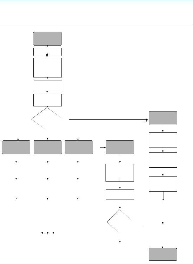
1.3WirelessHART installation flowchart
Figure 1-1. WirelessHART installation flowchart
START HERE
Set Device Tag
(page 11)
Join Device to Network by Setting Network
ID and Join Key (page 12)
Configure
Update Rate
(page 12)
Set Process
Variable Units
(page 13)
|
|
|
|
|
|
Bench |
|
|
|
|
|
|
|
|
|
|
|
|||||||
|
|
|
|
Configuration |
|
|
|
|
|
|
|
|
|
|
|
|||||||||
|
|
|
|
No |
||||||||||||||||||||
|
|
|
|
|||||||||||||||||||||
|
|
|
|
and Calibration |
|
|
|
|
|
|
|
|
|
|
|
|||||||||
|
|
|
|
|
|
|
|
|
|
|
|
|
|
|||||||||||
|
|
|
|
|
|
|
|
|
|
|
|
|
|
|
|
|
|
|
|
|
|
|
|
|
|
|
|
|
|
|
|
|
|
|
|
|
|
|
|
|
|
|
|
|
|
|
|
|
|
|
|
|
|
|
|
|
|
Yes |
|
|
|
|
|
|
|
|
|
|
|
|
|
|
|
|
|
|
|
|
|
|
|
|
|
|
|
|
|
|
|
|
|
|
|
|
|
|
|
|
|
|
|
|
|
|
|
|
|
|
|
|
|
|
|
|
|
|
|
|
|
|
|
|
|
|
Configure for |
|
Configure for |
|
|
|
|
Configure for |
|||||||||||||||||
Pressure |
|
|
|
|
|
Level |
|
|
|
|
Flow |
|
|
|||||||||||
|
|
|
|
|
|
|
||||||||||||||||||
|
|
|
|
|
|
|
|
|
|
|
|
|
|
|
|
|
|
|
|
|
|
|
|
|
|
|
|
|
|
|
|
|
|
|
|
|
|
|
|
|
|
|
|
|
|
|
|
|
|
|
|
|
|
|
|
|
|
|
|
|
|
|
|
|
|
|
|
|
|
|
|
|
|
|
Set Pressure to |
|
Configure |
|
|
|
|
|
Configure |
|
|
|
|
||||||||||||
PV |
|
Scaled Variable |
|
|
|
|
Scaled Variable |
|
|
|
|
|||||||||||||
(page 13) |
|
(page 16) |
|
|
|
|
|
(page 16) |
|
|
|
|
||||||||||||
|
|
|
|
|
|
|
|
|
|
|
|
|
|
|
|
|
|
|
|
|
|
|
|
|
|
|
|
|
|
|
|
|
|
|
|
|
|
|
|
|
|
|
|
|
|
|
|
|
|
|
|
|
|
|
|
|
|
|
|
|
|
|
|
|
|
|
|
|
|
|
|
|
|
|
|
|
|
|
|
|
|
|
|
|
|
|
|
|
|
|
|
|
|
|
|
|
|
|
|
Set Range |
|
Set Scaled |
|
|
|
|
|
Set Scaled |
|
|
|
|||||||||||||
Points |
|
Variable to PV |
|
|
|
|
Variable to PV |
|
|
|
||||||||||||||
(page 14) |
|
(page 13) |
|
|
|
|
|
(page 13) |
|
|
|
|||||||||||||
|
|
|
|
|
|
|
|
|
|
|
|
|
|
|
|
|
|
|
|
|
|
|||
|
|
|
|
|
|
|
|
|
|
|
|
|
|
|
|
|
|
|
|
|
|
|
|
|
|
|
|
|
|
|
|
|
|
|
|
|
|
|
|
|
|
|
|
|
|
|
|
|
|
Select Transfer |
|
Set Range Points |
|
|
|
|
Set Range Points |
|
|
|
||||||||||||||
Function for |
|
(page 14) |
|
|
|
|
|
(page 14) |
|
|
|
|||||||||||||
Percent of Range |
|
|
|
|
|
|
|
|
|
|
|
|
|
|
|
|
|
|
|
|
|
|
||
(page 15) |
|
|
|
|
|
|
|
|
|
|
|
|
|
|
|
|
|
|
|
|
|
|
||
|
|
|
|
|
|
|
|
|
|
|
|
|
|
|
|
|
|
|
|
|
|
|||
|
|
|
|
|
|
|
|
|
|
|
|
|
|
|
|
|
|
|
|
|
|
|
|
|
|
|
|
|
|
|
|
|
|
|
|
|
|
|
|
|
|
|
|
|
|
|
|
|
|
|
|
|
|
|
|
|
|
|
|
|
|
|
|
|
|
|
|
|
|
|
|
|
|
|
|
|
|
|
|
|
|
|
|
|
|
|
|
|
|
|
|
|
|
|
|
|
|
|
|
Field Install
Mount
Transmitter
(page 36)
Verify
Check Process
Connection (page 43)
Review
Transmitter
Configuration (page 20)
Install Power
Module (page 13)
Apply Pressure
|
|
|
|
|
|
|
|
|
|
|
|
|
|
|
|
|
|
|
|
Confirm |
|
||
|
|
|
|
|
|
|
|
Transmitter |
|
||
|
|
|
|
|
|
|
|
Configuration |
|
||
|
|
|
|
|
|
|
|
(page 20) |
|
||
Within |
|
|
|
|
|
|
|||||
|
|
|
|
|
|
||||||
Specifications? |
|
|
|
|
|
|
|||||
Yes |
|||||||||||
|
|
|
|
|
|||||||
|
|
|
|
|
|
|
|
Trim the |
|||
|
|
|
|
|
|
||||||
|
|
|
|
|
|
|
|
Transmitter |
|||
|
|
|
|
|
|
|
|
(page 67) |
|||
|
|
|
|
|
|||||||
|
|
No |
|
|
|
|
|
|
|
||
|
|
|
|
|
|
|
|||||
Refer to |
|
|
|
|
|
|
|||||
|
|
|
|
|
|
||||||
Section 5: |
|
|
|
|
|
|
|||||
Operation and |
|
|
|
Done |
|||||||
maintenance |
|
|
|
||||||||
|
|
|
|
|
|
|
|
|
|
|
|
Introduction |
3 |

Section 1: Introduction |
Reference Manual |
May 2013 |
00809-0100-4102, Rev AA |
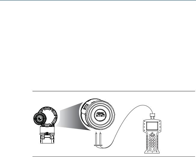
1.4Transmitter overview
The Rosemount 2051C Coplanar design is offered for Differential Pressure (DP), Gage Pressure (GP) and Absolute Pressure (AP) measurements. The Rosemount 2051C utilizes capacitance sensor technology for DP and GP measurements. The Rosemount 2051T and 2051CA utilize piezo-resistive sensor technology for AP and GP measurements.
The major components of the Rosemount 2051 Wireless transmitter are the sensor module and the electronics housing. The sensor module contains the oil filled sensor system (isolating diaphragms, oil fill system, and sensor) and the sensor electronics. The sensor electronics are installed within the sensor module and include a temperature sensor, a memory module, and the analog to digital signal converter (A/D converter). The electrical signals from the sensor module are transmitted to the output electronics in the electronics housing. The electronics housing contains the output electronics board, the antenna, and the battery. The basic block diagram of the Rosemount 2051CD Wireless device is illustrated in Figure 1-3 on page 5.
For the Rosemount 2051, pressure is applied to the isolating diaphragm(s). The oil deflects the sensor which then changes its capacitance or voltage signal. This signal is then changed to a digital signal by the Signal Processing Module. The microprocessor then takes the signals from the Signal Processing Module and calculates the correct output of the transmitter. This signal is then sent via wireless communication to the Gateway.
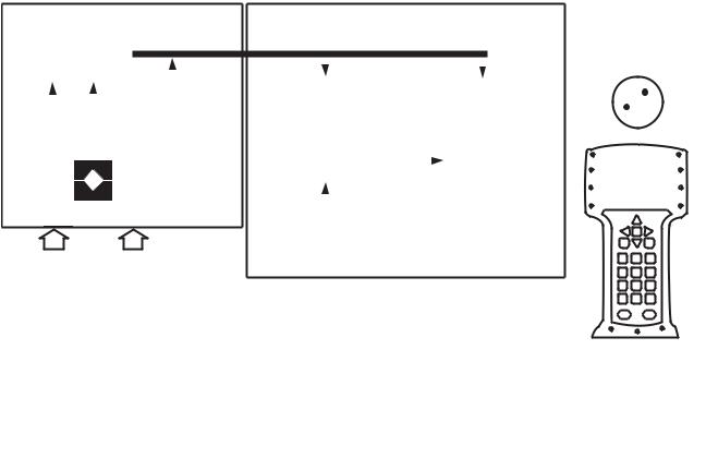
An optional LCD can be ordered that connects directly to the output electronics board which maintains direct access to the signal terminals. The display indicates output and abbreviated diagnostic messages. A clear display cover is provided. For WirelessHART output, the LCD Display features a three-line display. The first line describes the process variable measured, the second line displays the measured value, and the third line displays engineering units. The LCD can also display diagnostics messages.
Note
LCD Display utilizes a 3-line, 7-digit character display and can display output and diagnostic messages. See Figure 1-2.
Figure 1-2. LCD Display
LCD Display
4 |
Introduction |
Reference Manual |
Section 1: Introduction |
||
00809-0100-4102, Rev AA |
May 2013 |
||
|
|
|
|
|
|
|
|
Figure 1-3. Block diagram of operation
A B C
|
Signal Processing |
|
|
|
|
|
|
|
|
|
|
|
|
|
|
|
|
|
|
|
|
|
|
|
||||||||
|
|
|
|
|
|
|
|
|
|
|
|
|
|
|
|
|
|
|
|
|
|
|
|
|||||||||
|
|
|
|
|
|
|
|
|
|
|
|
|
|
|
|
|
|
|
|
|
|
|
|
|
|
|
|
|
|
|
|
|
|
|
|
|
|
|
|
|
|
|
|
|
|
|
|
|
|
|
|
|
|
|
|
|
|
|
|
|
|
|
|
|
|
|
|
|
|
|
|
|
|
|
|
|
|
|
|
|
|
|
Microprocessor |
|
|
|
|
Local HART |
|
|
|
|
|
|
|
|
||
|
|
|
|
|
|
|
|
|
|
|
|
|
|
|
|
|
Sensor linearization |
|
|
|
|
|
|
|
|
|
|
|
|
|||
|
|
|
|
|
|
|
|
|
|
Sensor Module |
|
|
|
|
|
|
Handheld |
|
|
|
|
|
|
|
|
|||||||
|
Temp. |
|
|
|
|
|
|
Rerange |
|
|
|
Communicator |
|
|
|
|
|
|
|
|
||||||||||||
|
|
|
|
|
|
|
Memory |
|
|
|
|
|
|
|
|
|
|
|
|
|||||||||||||
|
Sensor |
|
|
|
|
|
|
|
|
|
|
|
Diagnostics |
|
|
|
|
|
|
|
|
|
|
|
|
|
|
|||||
|
|
|
|
|
|
|
|
|
|
|
|
|
|
|
|
|
Engineering units |
|
|
|
|
|
|
|
|
|
|
|
|
|
|
|
|
|
|
|
|
|
|
|
|
|
|
|
|
|
|
|
|
|
|
|
|
WirelessHART |
|
|
|
|
|
|
|
||||
|
|
|
|
|
|
|
|
|
|
|
|
|
|
|
|
|
|
|
|
|
|
|
|
|
|
|
|
|||||
|
|
|
|
|
|
|
|
|
|
|
|
|
|
|
|
|
Communication |
|
|
|
|
Communication |
|
|
|
|
|
|
|
|||
|
|
|
|
|
|
|
|
|
|
|
|
|
|
|
|
|
|
|
|
|
|
|
|
|
|
|
|
|||||
|
|
|
|
|
|
|
|
|
|
|
|
|
|
|
|
|
|
|
|
|
|
|
|
|
|
|
|
|
|
|
|
|
|
|
|
|
|
|
|
|
|
|
|
|
|
|
|
|
|
|
|
|
|
|
|
|
|
|
|
|
|
|
|
|
|
|
|
|
|
|
|
|
|
|
|
|
|
|
|
|
|
|
|
|
|
|
|
|
|
|
|
|
|
|
|
|
|
|
|
|
|
|
|
|
|
|
|
|
|
|
|
|
|
|
|
Memory |
|
|
|
|
|
|
|
|
|
|
|
|
|
||
|
|
|
|
|
|
|
|
|
|
|
|
|
|
|
|
|
Configuration |
|
|
|
|
|
|
|
|
|
|
|
|
|
||
|
|
|
|
|
|
|
|
|
|
|
|
|
|
|
|
|
|
|
|
|
|
|
|
|
|
|
|
|
|
|||
|
|
|
|
|
|
|
|
|
|
|
|
|
|
|
|
|
|
|
|
|
|
|
|
|
|
|
|
|
|
|||
|
|
|
|
|
|
|
|
|
|
|
|
|
|
|
|
|
|
|
|
|
|
|
|
|
|
|
|
|
|
|
|
|
|
|
|
|
|
|
|
|
|
|
|
|
|
|
|
|
|
|
|
|
|
|
|
|
|
|
|
|
|
|
|
|
|
|
|
|
|
|
|
|
|
|
|
|
|
|
|
|
|
|
|
|
|
|
|
|
|
|
|
|
|
|
|
|
|
|
|
|
|
|
|
|
|
|
|
|
|
|
|
|
|
|
|
|
|
|
|
|
|
|
|
|
|
|
|
|
|
|
|
|
|
|
|
|
|
|
|
|
|
|
|
|
|
|
|
|
|
|
|
|
|
|
|
|
|
|
|
|
|
|
|
|
|
|
|
|
|
|
|
|
|
|
|
|
|
|
|
|
|
|
|
|
|
|
|
|
|
|
|
|
|
|
|
|
|
|
|
|
|
|
|
|
|
|
|
|
|
|
|
|
|
|
|
|
|
|
|
|
|
|
|
|
|
|
|
|
|
|
|
|
|
|
|
|
|
|
|
|
|
|
|
|
|
|
|
|
|
|
|
|
|
|
|
|
|
|
|
|
|
|
|
|
|
|
|
|
|
|
|
|
|
|
|
|
|
|
|
|
|
|
|
|
|
|
|
|
|
|
|
|
|
|
|
|
|
|
|
|
|
|
|
|
|
|
|
|
|
|
|
|
|
|
|
|
|
|
|
|
|
|
|
|
|
|
|
|
|
|
|
|
|
|
|
|
|
|
|
|
|
|
|
|
|
|
|
|
|
|
|
|
|
|
|
|
|
|
|
|
|
|
|
|
|
|
|
|
|
|
|
|
|
|
|
|
|
|
|
|
|
|
|
|
|
|
|
|
|
|
|
|
|
|
|
|
|
|
|
|
|
|
|
|
|
|
|
|
|
|
|
|
|
|
|
|
|
|
|
|
|
|
|
|
|
|
|
|
|
|
|
|
|
|
|
|
|
|
|
|
|
|
|
|
|
|
|
|
|
|
|
|
|
|
|
|
|
|
|
|
|
|
|
|
|
|
|
|
|
|
|
|
|
|
|
|
|
|
|
|
|
|
|
|
|
|
|
|
|
|
|
|
|
|
|
|
|
|
|
|
|
|
|
|
|
|
|
|
|
|
|
|
|
|
|
|
|
|
|
|
|
|
|
|
|
|
|
|
|
|
|
|
|
|
|
|
|
|
|
|
|
|
|
|
|
|
|
|
|
|
|
|
|
|
|
|
|
|
|
|
|
|
|
|
|
|
|
|
|
|
|
|
|
|
|
|
|
|
|
|
|
|
|
|
|
|
|
|
|
|
|
|
|
D
A.Sensor Module
B.Electronics Board
C.WirelessHART Signal to Control System
D.Field Communicator
1.5Considerations before transmitter installation
1.5.1Wireless considerations
Power up sequence
The Power Module should not be installed on any wireless device until the Smart Wireless Gateway is installed and functioning properly. This transmitter uses the Green Power Module (order model number 701PGNKF). Wireless devices should also be powered up in order of proximity from the Smart Wireless Gateway, beginning with the closest. This will result in a simpler and faster network installation. Enable Active Advertising on the Gateway to ensure that new devices join the network faster. For more information, see the Smart Wireless Gateway Manual (Doc. No. 00809-0200-4420).
Antenna position
The internal antenna is designed for multiple mounting orientations. The transmitter should be mounted according to best practices for your pressure measurement application.
Introduction |
5 |
Section 1: Introduction |
Reference Manual |
May 2013 |
00809-0100-4102, Rev AA |
Network design best practices
When mounting the device, recommended practices should be considered to achieve the best wireless performance. See Appendix D: Network design best practices for more information on recommended practices.
Field communicator connections
The Power Module needs to be installed in the device for the Field Communicator to interface with the Rosemount 2051. The Field Communicator connections are located on the Power Module. To communicate to the transmitter, connect the Field Communicator to the COMM port connections on the Power Module. This transmitter uses the Green Power Module; please order model number 701PGNKF. Field communication with this device requires a HART-based Field Communicator using the correct Rosemount 2051 Wireless DD. The Power Module is keyed and can only be inserted in one orientation. Refer to Figure 1-4 for instructions on connecting the Field Communicator to the 2051.
Figure 1-4. Field Communicator Connections
1.5.2Mechanical
Location
When choosing an installation location and position, take into account access to the power module compartment for easy power module replacement.
Electronics cover
The electronics cover is tightened so that polymer contacts polymer. When removing the electronics cover, ensure that there is no damage done to the o-ring. If damaged replace before reattaching cover, ensuring polymer contacts polymer (i.e. no o-ring visible).
1.5.3Electrical
Power module
The Rosemount 2051 Wireless Pressure Transmitter is self-powered. The Power Module contains a primary lithium-thionyl chloride battery (Green Power Module, model number
6 |
Introduction |

Reference Manual |
Section 1: Introduction |
00809-0100-4102, Rev AA |
May 2013 |
701PGNKF). Each battery contains approximately 5 grams of lithium. Under normal conditions, the battery materials are self-contained and are not reactive as long as the battery and the Power Module are maintained. Care should be taken to prevent thermal, electrical, or mechanical damage. Contacts should be protected to prevent premature discharge.
Use caution when handling the Power Module, it may be damaged if dropped from heights in excess of 6.10 m (20 ft).
1.5.4Environmental
Verify that the operating atmosphere of the transmitter is consistent with the appropriate hazardous locations certifications.
Temperature effects
The transmitter will operate within specifications for ambient temperatures between -40 and 85 °C (-40 and 185 °F).
Heat from the process is transferred to the transmitter housing. If the process temperature is high, the ambient temperature will need to be lower to account for heat transferred to the transmitter housing. See “Process Temperature Limits” on page 96 for process temperature derating.
1.6Service support
Within the United States, call the Emerson Process Management Instrument and Valve Response Center using the 1-800-654-RSMT (7768) toll-free number. This center, available 24 hours a day, will assist you with any needed information or materials.
The center will ask for product model and serial numbers, and will provide a Return Material Authorization (RMA) number. The center will also ask for the process material to which the product was last exposed.
For inquiries outside of the United States, contact the nearest Emerson Process Management representative for RMA instructions.
To expedite the return process outside of the United States, contact the nearest Emerson Process Management representative.
Individuals who handle products exposed to a hazardous substance can avoid injury if they are informed of and understand the hazard. The product being returned will require a copy of the required Material Safety Data Sheet (MSDS) for each substance must be included with the returned goods.
Introduction |
7 |

Section 1: Introduction |
Reference Manual |
|
May 2013 |
00809-0100-4102, Rev AA |
|
|
|
|
|
|
|
|
|
|
Shipping considerations for wireless products (Lithium Batteries: Green Power Module, model number 701PGNKF):
The unit was shipped to you without the Power Module installed. Please remove the Power Module from the unit prior to shipping.
Each power module contains a primary lithium-thionyl chloride battery. Primary lithium batteries are regulated in transportation by the U.S. Department of Transportation, and are also covered by IATA (International Air Transport Association), ICAO (International Civil Aviation Organization), and ARD (European Ground Transportation of Dangerous Goods). It is the responsibility of the shipper to ensure compliance with these or any other local requirements. Please consult current regulations and requirements before shipping.
The Power Module contains a primary lithium-thionyl chloride battery (Green Power Module, model number 701PGNKF). Each Power Module contains approximately 5 grams of lithium. Under normal conditions, the Power Module materials are self-contained and are not reactive as long as the batteries and the module integrity are maintained. Care should be taken to prevent thermal, electrical or mechanical damage. Contacts should be protected to prevent premature discharge. Power Module hazards remain when cells are discharged.
Power Module should be stored in a clean and dry area. For maximum battery life, storage temperature should not exceed 86 °F (30 °C).
Emerson Process Management Instrument and Valve Response Center representatives will explain the additional information and procedures necessary to return goods exposed to hazardous substances.
1.7Product Recycling/Disposal
Recycling of equipment and packaging should be taken into consideration and disposed of in accordance with local and national legislation/regulations.
8 |
Introduction |
Reference Manual |
Section 2: Configuration |
00809-0100-4102, Rev AA |
May 2013 |
Section 2 Configuration
Overview . . . . . . . . . . . . . . . . . . . . . . . . . . . . . . . . . . . . . . . . . . . . . . . . . . . . . . . . . . . . . . . page 9 Safety messages . . . . . . . . . . . . . . . . . . . . . . . . . . . . . . . . . . . . . . . . . . . . . . . . . . . . . . . . . page 9 Required bench top configuration . . . . . . . . . . . . . . . . . . . . . . . . . . . . . . . . . . . . . . . . . page 10 Basic setup . . . . . . . . . . . . . . . . . . . . . . . . . . . . . . . . . . . . . . . . . . . . . . . . . . . . . . . . . . . . . . page 11 Review configuration data . . . . . . . . . . . . . . . . . . . . . . . . . . . . . . . . . . . . . . . . . . . . . . . . page 20 Review operating parameters . . . . . . . . . . . . . . . . . . . . . . . . . . . . . . . . . . . . . . . . . . . . . page 21 Review operating parameters . . . . . . . . . . . . . . . . . . . . . . . . . . . . . . . . . . . . . . . . . . . . . page 21 Configuring the LCD display . . . . . . . . . . . . . . . . . . . . . . . . . . . . . . . . . . . . . . . . . . . . . . . page 22 Configuring the LCD display . . . . . . . . . . . . . . . . . . . . . . . . . . . . . . . . . . . . . . . . . . . . . . . page 22 Detailed transmitter setup . . . . . . . . . . . . . . . . . . . . . . . . . . . . . . . . . . . . . . . . . . . . . . . . page 23 Diagnostics and service . . . . . . . . . . . . . . . . . . . . . . . . . . . . . . . . . . . . . . . . . . . . . . . . . . . page 24 Advanced Functions for HART Protocol . . . . . . . . . . . . . . . . . . . . . . . . . . . . . . . . . . . . . page 27
2.1Overview
This section contains information on commissioning and tasks that should be performed on the bench prior to installation.
Field Communicator and AMS Device Manager instructions are given to perform configuration functions. For convenience, Field Communicator fast key sequences are labeled “Fast Keys” for each software function below the appropriate headings.
Full Field Communicator menu trees and fast key sequences are available in Appendix C: Field Communicator Menu Trees and Fast Keys.
2.2Safety messages
Procedures and instructions in this section may require special precautions to ensure the safety of the personnel performing the operations. Information that raises potential safety issues is indicated by a warning symbol ( ). Refer to the following safety messages before performing an operation preceded by this symbol.
Configuration |
9 |

Section 2: Configuration |
Reference Manual |
May 2013 |
00809-0100-4102, Rev AA |
Warnings ( )
)
Failure to follow these installation guidelines could result in death or serious injury.
Make sure only qualified personnel perform the installation. Explosions could result in death or serious injury:
Installation of this transmitter in an explosive environment must be in accordance with the appropriate local, national, and international standards, codes, and practices. Please review the approvals section of the 2051 Wireless reference manual for any restrictions associated with a safe installation.
Before connecting a Field Communicator in an explosive atmosphere, make sure the instruments are installed in accordance with intrinsically safe or non-incendive field wiring practices.
Verify that the operating atmosphere of the transmitter is consistent with the appropriate hazardous locations certifications
Process leaks could result in death or serious injury.
Install and tighten process connectors before applying pressure. Electrical shock could cause death or serious injury.
Avoid contact with the leads and terminals. High voltage that may be present on leads can cause electrical shock.
This device complies with Part 15 of the FCC Rules. Operation is subject to the following conditions: This device may not cause harmful interference. This device must accept any interference received, including interference that may cause undesired operation.
This device must be installed to ensure a minimum antenna separation distance of 20cm (8 in.) from all persons.
2.3Required bench top configuration
Bench top configuration requires a Field Communicator, AMS, or any WirelessHART Communicator. Connect the Field Communicator leads to the terminals labeled “COMM” on the Power Module. See Figure 2-1 on page 11.
Bench top configuration consists of testing the transmitter and verifying transmitter configuration data. 2051 Wireless transmitters must be configured before installation. Configuring the transmitter on the bench before installation using a Field Communicator, AMS, or any WirelessHART Communicator ensures that all network settings are working correctly.
When using a Field Communicator, any configuration changes made must be sent to the transmitter by using the “Send” key (F2). AMS configuration changes are implemented when the “Apply” button is clicked.
AMS Wireless Configurator
AMS is capable of connecting to devices either directly, using a HART modem, or wirelessly via the Smart Wireless Gateway. When configuring the device, double click the device icon or right click and select Configure.
10 |
Configuration |

Reference Manual |
Section 2: Configuration |
00809-0100-4102, Rev AA |
May 2013 |
2.3.1Connection diagrams
Bench hook-up
Connect the bench equipment as shown in Figure 2-1 on page 11, and turn on the Field Communicator by pressing the ON/OFF key or log into AMS. The Field Communicator or AMS will search for a HART-compatible device and indicate when the connection is made. If the Field Communicator or AMS fail to connect, it indicates that no device was found. If this occurs, refer to Section 6: Troubleshooting.
Field hook-up
Figure 2-1 on page 11 illustrates the wiring for a field hook-up with a Field Communicator or AMS. The Field Communicator or AMS may be connected at “COMM” on the transmitter Power Module.
Figure 2-1. Field Communicator Connection
For HART communication, a 2051 WirelessHART DD is required.
2.4Basic setup
2.4.1Set device tag
Fast Keys |
2, 2, 9, 1, 1 |
|
|
The tag is used to identify the device. You can use an 8 to 32 character tag.
|
1. |
From the Home screen, select 2: Configure |
|
|
2. |
Select 2: Manual Setup |
|
|
3. |
Select 9: Device Information |
|
|
4. |
Select 1: Identification |
|
Configuration |
5. |
Select 1: Tag |
11 |
|
|

Section 2: Configuration |
Reference Manual |
May 2013 |
00809-0100-4102, Rev AA |
2.4.2Join device to network
Fast Keys |
2, 1, 3 |
|
|
In order to communicate with the Smart Wireless Gateway, and ultimately the Host System, the transmitter must be configured to communicate over the wireless network. This step is the wireless equivalent of connecting wires from a transmitter to the host system.
1.From the Home screen, select 2: Configure.
2.Select 1: Guided Setup.
3.Select 3: Join Device to Network.
Using a Field Communicator or AMS, enter the Network ID and Join Key so that they match the Network ID and Join Key of the Smart Wireless Gateway and other devices in the network. If the Network ID and Join Key are not identical to those set in the Gateway, the transmitter will not communicate with the network. The Network ID and Join Key may be obtained from the Smart Wireless Gateway on the Setup>Network>Settings page on the web server.
2.4.3Configure update rate
Fast Keys |
2, 1, 4 |
|
|
The Update Rate is the frequency at which a new measurement is taken and transmitted over the wireless network. This by default is 1 minute. This may be changed at commissioning, or at any time via AMS Wireless Configurator. The Update Rate is user selectable from 1 second to 60 minutes.
1.From the Home screen, select 2: Configure.
2.Select 1: Guided Setup.
3.Select 4: Configure Update Rate.
12 |
Configuration |

Reference Manual |
Section 2: Configuration |
00809-0100-4102, Rev AA |
May 2013 |
2.4.4Set process variable units
Fast Keys |
2, 2, 2, 3 |
|
|
The PV Unit command sets the process variable units to allow you to monitor your process using the appropriate units of measure.
To select a unit of measure for the PV:
1.From the Home screen, select 2: Configure.
2.Select 2: Manual Setup.
3.Select 2: Pressure.
4.Select 3: Unit to select from the following engineering units:
|
inH2O at 4 °C |
|
mmH2O at 68 °F |
|
mmHg |
|
inH2O at 60 °F |
|
cmH2O at 4 °C |
|
Psi |
|
inH2O at 68 °F |
|
mH2O at 4 °C |
|
Atm |
|
ftH2O at 4 °C |
|
inHg at 0 °C |
|
Torr |
|
ftH2O at 60 °F |
|
mmHg at 0 °C |
|
Pascals |
|
ftH2O at 68 °F |
|
cmHg at 0 °C |
|
hectoPascals |
|
mmH2O at 4 °C |
|
mHg at 0 °C |
|
Kilopascals |
Mpa
Bar
Mbar
g/cm2
kg/cm2
kg/m2
2.4.5Remove Power Module
After the sensor and network have been configured, remove the Power Module and replace the housing cover. The Power Module should be inserted only when the device is ready to be commissioned.
Use caution when handling the Power Module. The Power Module may be damaged if dropped from heights in excess of 6.10 m (20 ft).
2.5Configure for Pressure
2.5.1Re-Mapping device variables
The re-mapping function allows the transmitter primary, secondary, tertiary, and quaternary variables (PV, SV, TV, and QV) to be configured in one of two configurations. The user may select either the option of Classic mapping or Scaled Variable Mapping, see Table 2-1 for what is mapped to each variable. All variables can be remapped with a Field Communicator or AMS Device Manager.
Configuration |
13 |

Section 2: Configuration |
|
Reference Manual |
||
May 2013 |
|
00809-0100-4102, Rev AA |
||
|
|
|
|
|
|
Table 2-1. Variable Mapping |
|
|
|
|
|
|
|
|
|
|
Classic Mapping |
Scaled Variable Mapping |
|
|
|
|
|
|
|
PV |
Pressure |
Scaled Variable |
|
|
SV |
Sensor Temperature |
Pressure |
|
|
TV |
Electronics Temperature |
Sensor Temperature |
|
|
QV |
Supply Voltage |
Supply Voltage |
|
|
|
|
|
|
Note
The variable assigned to the primary variable drives the output. This value can be selected as Pressure or Scaled Variable.
Re-mapping using a Field Communicator
From the HOME screen, enter the fast key sequence
Fast Keys |
2, 2, 6, 1 |
|
|
Re-mapping using AMS Device Manager
Right click on the device and select Configure.
1.Select Manual Setup and click on the HART tab.
2.Assign Primary, secondary, tertiary and quaternary variables under Variable Mapping.
3.Click Send.
4.Carefully read the warning and click Yes if it is safe to apply the changes.
2.5.2Set range points
From the HOME screen, enter the fast key sequence
Fast Keys |
2, 1, 1, 5 |
|
|
The Range Values command sets the lower and upper range values used for the percent of range measurement.
Note
Transmitters are shipped from Rosemount Inc. fully calibrated per request or by the factory default of full scale (span = upper range limit).
1.From the Home screen, select 2: Configure
2.Select 1: Guided Setup
3.Select 1: Basic Setup
4.Select 5: Range Values
14 |
Configuration |
Reference Manual |
Section 2: Configuration |
00809-0100-4102, Rev AA |
May 2013 |
2.5.3Set transmitter percent of range (transfer function)
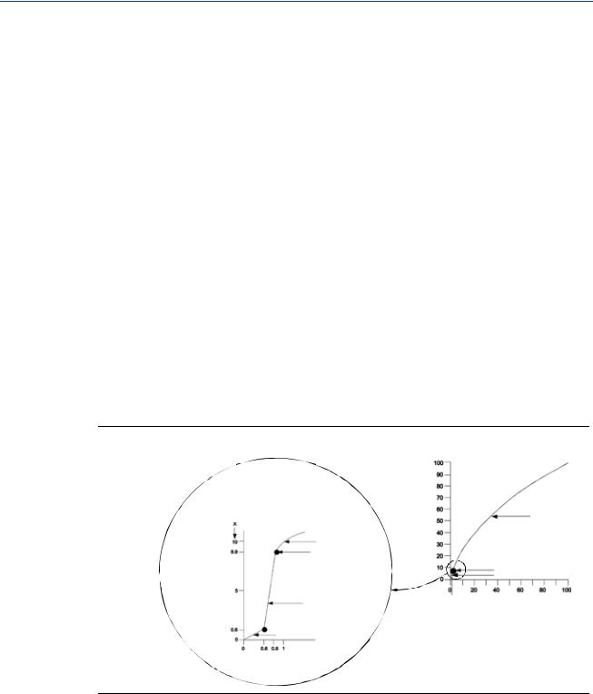
The Rosemount 2051 Wireless transmitter has two transfer functions for pressure applications: Linear and Square Root. As shown in Figure 2-2 on page 15, activating the square root options the transmitter analog output proportional to flow.
However, for DP Flow and DP Level applications it is recommended to use Scaled Variable. Refer to “Diagnostics and service” on page 24 for setup instructions.
From 0 to 0.6 percent of the ranged pressure input, the slope of the curve is unity (y = x). This allows accurate calibration near zero. Greater slopes would cause large changes in output (for small changes at input). From 0.6 percent to 0.8 percent, curve slope equals 42 (y = 42x) to achieve continuous transition from linear to square root at the transition point.
Setting transmitter output with a Field Communicator
From the HOME screen, enter the fast key sequence
Fast Keys |
2, 2, 4, 2 |
|
|
Setting transmitter output with AMS Device Manager
Right click on the device and select Configure.
1.Click Manual Setup and choose output type from Transfer Function and click Send.
2.Carefully read the warning and click Yes if it is safe to apply the changes.
Figure 2-2. Square Root Output Transition Point
Full Scale |
|
|
Sq. Root |
Flow (%) |
|
|
Curve |
|
|
|
|
|
|
|
|
|
|
Sq. Root Curve |
|
|
Transition Point |
Transition Point |
|
|
|
|
|
|
|
|
Linear Section |
Slope=42
Slope=1
Configuration |
15 |

Section 2: Configuration |
Reference Manual |
May 2013 |
00809-0100-4102, Rev AA |
2.6Configure for Level and Flow
2.6.1Configuring scaled variable
The Scaled Variable configuration allows the user to create a relationship/conversion between the pressure units and user-defined/custom units. There are two use cases for Scaled Variable. The first use case is to allow custom units to be displayed on the transmitter's LCD Display. The second use case is to allow custom units to drive the transmitter's PV output.
If the user desires custom units to drive the PV output, Scaled Variable must be re-mapped as the primary variable. Refer to “Re-Mapping device variables” on page 18.
The Scaled Variable configuration defines the following items:
Scaled Variable units - Custom units to be displayed.
Scaled data options - Defines the transfer function for the application
–Linear
–Square root
Pressure value position 1 - Lower known value point with consideration of linear offset.
Scaled Variable value position 1 - Custom unit equivalent to the lower known value point.
Pressure value position 2 - Upper known value point
Scaled Variable value position 2 - Custom unit equivalent to the upper known value point
Linear offset - The value required to zero out pressures affecting the desired pressure reading.
Low flow cutoff - Point at which output is driven to zero to prevent problems caused by process noise. It is highly recommended to use the low flow cutoff function in order to have a stable output and avoid problems due to process noise at a low flow or no flow condition. A low flow cutoff value that is practical for the flow element in the application should be entered.
Configuring Scaled Variable using a Field Communicator
From the HOME screen, enter the fast key sequence
Device Dashboard Fast Keys |
2, 1, 7 |
|
|
1.Follow the screen prompts to configure Scaled Variable.
a.When configuring for level, select Linear under Select Scaled data options.
b.When configuring for flow, select Square Root under Select Scaled data options.
Configuring Scaled Variable using AMS Device Manager
Right click on the device and, select Configure.
1.Select the Scaled Variable tab and click the Scaled Variable button.
2.Follow screen prompts to configure Scaled Variable
16 |
Configuration |
Reference Manual |
Section 2: Configuration |
00809-0100-4102, Rev AA |
May 2013 |
a.When configuring for level applications, select Linear under Select Scaled data options.
b.When configuring for flow applications, select Square Root under Select Scaled data options.
DP Level Example
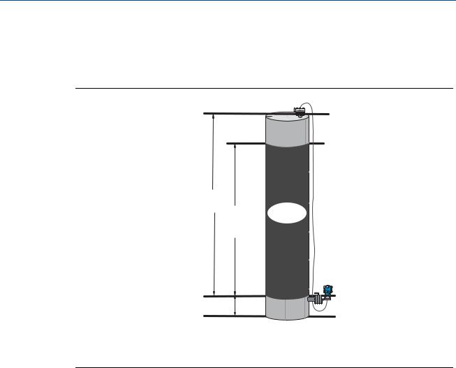
Figure 2-3. Example tank
A
D
B
C |
A.230 in.
B.200 in.
C.12 in.
D.0.94 sg
A differential transmitter is used in a level application. Once installed on an empty tank and taps vented, the process variable reading is -209.4 inH2O. The process variable reading is the head pressure created by fill fluid in the capillary. Based on Table 2-2 on page 2-17, the Scaled Variable configuration would be as follows:
Table 2-2. Scaled Variable Configuration for Tank Application
Scaled Variable units: |
inch |
|
|
Scaled data options: |
linear |
|
|
Pressure value position 1: |
0 inH2O |
Scaled Variable position 1: |
12 in. |
|
|
Pressure value position 2: |
188 inH2O |
Scaled Variable position 2: |
212 in. |
|
|
Linear offset: |
-209.4 inH2O |
DP Flow example
|
A differential pressure transmitter is used in conjunction with an orifice plate in a flow |
|
|
application where the differential pressure at full scale flow is 125 inH2O. In this particular |
|
Configuration |
application, the flow rate at full scale flow is 20,000 gallons of water per hour. It is highly |
17 |
|

Section 2: Configuration |
Reference Manual |
May 2013 |
00809-0100-4102, Rev AA |
recommended to use the low flow cutoff function in order to have a stable output and avoid problems due to process noise at a low flow or no flow condition. A low flow cutoff value that is practical for the flow element in the application should be entered. In this particular example, the low flow cutoff value is 1000 gallons of water per hour. Based on this information, the Scaled Variable configuration would be as follows:
Table 2-3. Scaled Variable Configuration for Flow Application
Scaled Variable units: |
gal/h |
|
|
Scaled data options: |
square root |
|
|
Pressure value position 2: |
125 inH2O |
|
|
Scaled Variable position 2: |
20,000 gal/h |
|
|
Low Flow Cutoff: |
1000 gal/h |
|
|
Note
Pressure value position 1 and Scaled Variable position 1 are always set to zero for a flow application. No configuration of these values is required.
2.6.2Re-Mapping device variables
The re-mapping function allows the transmitter primary, secondary, tertiary, and quaternary variables (PV, SV, TV, and QV) to be configured in one of two configurations. The user may select either the option of Classic Mapping or Scaled Variable Mapping, see Table 2-4 for what is mapped to each variable. All variables can be remapped with a Field Communicator or AMS Device Manager.
Table 2-4. Variable Mapping
|
Classic Mapping |
Scaled Variable Mapping |
|
|
|
PV |
Pressure |
Scaled Variable |
SV |
Sensor Temperature |
Pressure |
TV |
Electronics Temperature |
Sensor Temperature |
QV |
Supply Voltage |
Supply Voltage |
|
|
|
Note
The variable assigned to the primary variable drives the output. This value can be selected as Pressure or Scaled Variable.
Re-mapping using a Field Communicator
From the HOME screen, enter the fast key sequence
Fast Keys |
2, 2, 6, 1, 1 |
|
|
Re-mapping using AMS Device Manager
Right click on the device and select Configure.
18 |
Configuration |
Loading...