


S |
|
|
|
|
|
|
|
GB |
|
|
INDEX |
|
|
A |
GENERAL INFORMATION .............................................................................. |
Page |
7 |
|||
|
A1 |
Introduction...................................................................................................................... |
|
Page |
7 |
|
|
A2 |
Definitions........................................................................................................................ |
|
Page |
7 |
|
|
A3 |
Typographical conventions .............................................................................................. |
Page |
7 |
||
|
A4 |
Machine and Manufacturer’s identification data............................................................... |
Page |
8 |
||
|
A5 |
Equipment identification .................................................................................................. |
Page |
8 |
||
|
A6 |
Copyright ......................................................................................................................... |
|
Page |
9 |
|
|
A7 |
Liability |
............................................................................................................................. |
|
Page |
9 |
|
A8 |
Keeping .........................................................................................................the manual |
Page |
9 |
||
|
A9 |
Users of ........................................................................................................the manual |
Page |
9 |
||
B GENERAL DESCRIPTION .......................................................OF MACHINE |
Page |
10 |
||||
|
B1 |
General .........................................................................................................description |
Page |
10 |
||
|
B2 |
Description .....................................................................................of machine modules |
Page |
10 |
||
|
|
B2.1 ........................................................................................................... |
Wash zone |
|
Page |
11 |
|
|
B2.2 ........................................................................................................... |
Rinse zone |
|
Page |
11 |
|
|
B2.3 ...................................................................................................... |
Prewash zone |
Page |
11 |
|
|
|
B2.4 ................................................................................View of module composition |
Page |
11 |
||
C |
TECHNICAL ...........................................................................................DATA |
|
Page |
12 |
||
|
C1 |
Main technical ..........................................................................................characteristics |
Page |
12 |
||
|
C2 Characteristics .......................................................................................of power supply |
Page |
13 |
|||
D TRANSPORT, ....................................................HANDLING AND STORAGE |
Page |
14 |
||||
|
D1 |
Introduction...................................................................................................................... |
|
Page |
14 |
|
|
|
D1.1 ...................................................................Transport: Instructions for the carrier |
Page |
14 |
||
|
D2 |
Handling .......................................................................................................................... |
|
Page |
15 |
|
|
|
D2.1 .....................................................................Procedures for handling operations |
Page |
15 |
||
|
|
D2.2 ........................................................................................................... |
Translation |
|
Page |
15 |
|
|
D2.3 ................................................................................................... |
Placing the load |
Page |
15 |
|
|
D3 |
Storage ............................................................................................................................ |
|
Page |
15 |
|
E |
INSTALLATION ...................................................................AND ASSEMBLY |
Page |
16 |
|||
|
E1 |
Customer ................................................................................................responsibilities |
Page |
16 |
||
|
E2 |
Characteristics ..............................................................................of the site installation |
Page |
16 |
||
|
E3 |
Machine .......................................................................................................space limits |
Page |
16 |
||
|
E4 |
Positioning ....................................................................................................................... |
|
Page |
16 |
|
|
E5 |
Disposal .........................................................................................................of packing |
Page |
16 |
||
|
E6 |
Plumbing .....................................................................................................connections |
Page |
16 |
||
|
|
E6.1 ................................................................................................. |
Plumbing circuits |
Page |
17 |
|
|
|
E6.2 ............................................................................................ |
Installation diagrams |
Page |
19 |
|
|
E7 |
Electrical ......................................................................................................connections |
Page |
25 |
||
|
E8 |
Installation ..................................................................of detergent/rinse aid dispensers |
Page |
26 |
||
|
|
E8.1 ......................................................................Arrangement for water connection |
Page |
26 |
||
|
|
................................... |
E8.1.1 Detergent concentration measurement probe |
Page |
27 |
|
|
|
.............................................................. |
E8.1.2 |
Liquid detergent dispensers |
Page |
27 |
|
|
......................................................................... |
E8.1.3 |
Rinse aid dispensers |
Page |
27 |
|
|
E8.2 .................................................................Arrangement for electrical connection |
Page |
27 |
||
ENGLISH
3
|
E9 |
Fitting curtains ................................................................................................................. |
|
Page |
28 |
|
E10 Installation of rack handling systems ............................................................................... |
Page |
29 |
||
|
|
E10.1 |
Arrangement for mechanical connection ............................................................. |
Page |
29 |
|
|
E10.2 |
Arrangement for electrical connection ................................................................. |
Page |
29 |
|
|
E10.3 |
Positioning of emergency switches ...................................................................... |
Page |
29 |
|
|
E10.4 |
Emergency stop reinstatement ............................................................................ |
Page |
30 |
F |
DESCRIPTION OF CONTROL PANEL ............................................................ |
Page |
31 |
||
|
F1 |
Basic controls .................................................................................................................. |
|
Page |
31 |
|
F2 Accessory function selection controls.............................................................................. |
Page |
31 |
||
G |
STARTING |
|
Page |
32 |
|
|
G1 Preliminary ...................................................checks, adjustments and operational tests |
Page |
32 |
||
|
|
G1.1 ........................................................................... |
Electrical and plumbing checks |
Page |
32 |
|
|
G1.2 .......................................................... |
Check the positioning of tank components |
Page |
32 |
|
|
............................................ |
G1.2.1 Check the fitting of filters and overflows |
Page |
32 |
|
|
............................................... |
G1.2.2 Check the fitting of arms and curtains |
Page |
32 |
|
G2 |
Starting ............................................................................................................................ |
|
Page |
32 |
H |
GENERAL .............................................................................SAFETY RULES |
Page |
33 |
||
|
H1 |
Introduction ...................................................................................................................... |
|
Page |
33 |
|
|
H1.1 ........................................................ |
Protection devices installed on the machine |
Page |
33 |
|
|
H1.2 ....................................................... |
Safety signs to be displayed on the machine |
Page |
33 |
|
H2 |
Decommissioning ............................................................................................................ |
|
Page |
34 |
|
H3 Instructions ..............................................................................for use and maintenance |
Page |
34 |
||
|
H4 |
Improper ....................................................................................................................use |
|
Page |
34 |
|
H5 |
Residual ..................................................................................................................risks |
|
Page |
35 |
I |
NORMAL MACHINE .................................................................................USE |
Page |
36 |
||
|
I1 |
Correct ......................................................................................................................use |
|
Page |
36 |
|
I2 |
Characteristics ..........................................of personnel trained for normal machine use |
Page |
36 |
|
|
|
I2.1 ........................ |
Characteristics of personnel enabled to operate on the machine |
Page |
36 |
|
|
...................................................... |
Operator qualified for normal use |
Page |
36 |
|
I3 |
Daily activation ..............................................................................................of machine |
Page |
36 |
|
|
|
I3.1 ......................................................................................................... |
Wash phase |
Page |
36 |
|
|
I3.2 ...................................................................................................... |
Rack jamming |
Page |
37 |
|
|
I3.3 ................................................................................................. |
Wash phase stop |
Page |
37 |
|
|
I3.4 ............................................................................................ |
Temperature display |
Page |
37 |
|
|
I3.5 ...................................................................................... |
Loading dishes on racks |
Page |
38 |
|
|
I3.6 ............................................................................................. |
Accessory functions |
Page |
38 |
|
|
I3.7 ............................................................................................................ |
|
Page |
39 |
|
|
I3.8 ................................................................................................... |
Emergency stop |
Page |
39 |
|
|
I3.9 ...................................................................................................... |
General alarm |
Page |
39 |
|
I4 |
Machine .............................................................................................................cleaning |
|
Page |
41 |
|
|
I4.1 ......................................................................................... |
Daily internal cleaning |
Page |
41 |
|
|
I4.2 .................................................................................................. |
Exterior cleaning |
Page |
41 |
|
I5 |
Long idle .............................................................................................................periods |
|
Page |
41 |
|
I6 |
Maintenance .................................................................................................................... |
|
Page |
42 |
|
|
I6.1 ...................................................................................... |
Preventive maintenance |
Page |
42 |
|
I7 |
Machine .............................................................................................................disposal |
|
Page |
42 |
|
I8 |
Troubleshooting ............................................................................................................... |
|
Page |
42 |
4

GB |
INDEX OF FIGURES AND TABLES |
|
|
INDEX OF FIGURES |
|
|
|
Figure 1 |
Reproduction of the marking/dataplate on the machine..................................................... |
Page |
8 |
Figure 2 |
Position of marking (machine left)...................................................................................... |
Page |
8 |
Figure 3 |
Position of marking (machine right).................................................................................... |
Page |
8 |
Figure 4 |
Technical data identification (Machine left) ........................................................................ |
Page |
8 |
Figure 5 |
Example of document and edition identification data......................................................... |
Page |
9 |
Figure 6 |
View of different configurations of compact rack-type dishwashers................................... |
Page |
10 |
Figure 7 |
Feet adjustment ................................................................................................................. |
Page |
16 |
Figure 8 |
Water connection ............................................................................................................... |
Page |
17 |
Figure 9 |
Installation diagram - Recommended table connection and fabrication............................. |
Page |
24 |
Figure 10 |
Electrical connections diagram .......................................................................................... |
Page |
25 |
Figure 11 |
Hole for detergent probe .................................................................................................... |
Page |
27 |
Figure 12 |
Arrangement for liquid detergent........................................................................................ |
Page |
27 |
Figure 13 |
Rinse aid connection.......................................................................................................... |
Page |
27 |
Figure 14 |
Diagram of curtain positioning on compact machines ....................................................... |
Page |
28 |
Figure 15 |
Handling electrical connection system............................................................................... |
Page |
29 |
Figure 16 |
Detail of electrical connection ............................................................................................ |
Page |
29 |
Figure 17 |
Examples of dishwasher and rack handling system couplings .......................................... |
Page |
30 |
Figure 18 |
Prewash module tank filters ............................................................................................... |
Page |
32 |
Figure 19 |
Wash/rinse module tank filters ........................................................................................... |
Page |
32 |
Figure 20 |
Prewash ............................................................................................................................. |
Page |
32 |
Figure 21 |
Wash .................................................................................................................................. |
Page |
32 |
Figure 22 |
Rinse.................................................................................................................................. |
Page |
32 |
Figure 23 |
Positioning of safety signs.................................................................................................. |
Page |
34 |
Figure 24 |
Positioning dishes .............................................................................................................. |
Page |
38 |
Figure 25 |
Positioning pans................................................................................................................. |
Page |
38 |
Figure 26 |
Positioning trays ................................................................................................................. |
Page |
38 |
Figure 27 |
Remove and cleaning filters............................................................................................... |
Page |
41 |
Figure 28 |
Remove and cleaning arms ............................................................................................... |
Page |
41 |
INDEX OF TABLES |
|
|
|
Table 1 |
Main technical characteristics, performance and consumption.......................................... |
Page |
13 |
Table 2 |
Control panel...................................................................................................................... |
Page |
31 |
Table 3 |
Residual risks..................................................................................................................... |
Page |
35 |
Table 4 |
Accessory functions ........................................................................................................... |
Page |
39 |
ENGLISH
5
Foreword
The instruction manual (hereinafter Manual) provides the operator with useful information for working correctly and safely, facilitating him in using the machine (hereinafter “machine”, “dishwasher” or “equipment”).
The following must not be considered a long and exacting list of warnings, but rather a set of instructions suitable for improving machine performance in every respect and, above all, preventing injury to persons and animals and damage to property due to improper operating procedures.
All persons involved in machine transport, installation, starting, use and maintenance, repair and dismantling must consult and carefully read this manual before performing the various operations, for the purpose of avoiding wrong and improper actions that could negatively affect the machine’s integrity or endanger persons.
The manual must always be available to operators and carefully kept in the place where the machine is used so that it is immediately at hand for consultation in case of doubts or whenever required.
If, after reading this manual, there are still doubts regarding machine use, do not hesitate to contact the Manufacturer, or the authorized assistance centre, to receive prompt and precise assistance for better operation and maximum efficiency of the machine.
During all phases of machine use, always respect the current regulations on safety, work hygiene and environmental protection. It is the user’s responsibility to make sure the machine is started and operated only in optimal safety conditions for persons, animals and property.
6
A GENERAL INFORMATION
A1 Introduction
This chapter describes the symbols used (that mark and identify the type of warning) and gives the definitions of terms used in the manual, responsibilities and copyright.
A2 Definitions
Listed below are the definitions of the main terms used in the Manual. Carefully read them before using the Manual.
Operator
an operator who carries out machine installation, adjustment, use, maintenance, cleaning, repair and transport.
Manufacturer
Electrolux Professional S.p.A. or any other assistance centre authorized by Electrolux Professional S.p.A..
Operator qualified for normal machine use
an operator who has been informed, instructed and trained regarding the tasks and hazards involved in normal machine use.
Specialized technician or Technical assistance
an operator instructed/trained by the Manufacturer and who, based on his professional and specific training, experience and knowledge of the accident-prevention regulations, is able to appraise the operations to be carried out on the machine and recognize and prevent possible risks. His professionalism covers the mechanical, electrotechnical and electronics fields.
Danger
source of possible injury or harm to health.
Hazardous situation
any situation where an operator is exposed to one or more hazards.
Risk
a combination of probabilities and risks of injury or harm to health in a hazardous situation.
Guards
safety measures consisting of the use of specific technical means (guards and safety devices) for protecting operators against dangers.
Guard
an element of a machine used specifically to provide protection by means of a physical barrier.
Safety device
a device (other than a guard) that eliminates or reduces the risk; it can be used alone or in combination with a guard.
Customer
the person who purchased the machine and/or who manages and uses it (e.g. company, entrepreneur, firm).
Emergency stop device |
ENGLISH |
|
a group of components intended for the emergency stop |
||
|
||
function; the device is activated with a single action and |
|
|
prevents or reduces damage to persons/machines/prop- |
|
|
erty/animals. |
|
|
|
||
Electrocution |
|
|
an accidental discharge of electric current on a human |
|
|
body. |
|
|
A3 Typographical conventions |
|
|
For best use of the manual, and therefore the machine, it |
|
|
is advisable to have good knowledge of the terms and |
|
|
typographical conventions used in the documentation. |
|
|
The following symbols are used in the manual to mark |
|
|
and identify the various types of hazards: |
|
|
WARNING! |
|
|
DANGER FOR THE HEALTH AND |
|
|
SAFETY OF OPERATORS. |
|
|
WARNING! |
|
|
DANGER OF ELECTROCUTION - DAN- |
|
|
GEROUS VOLTAGE. |
|
|
Machine guards and protection devices marked with this |
|
|
symbol must only be opened by qualified personnel, |
|
|
after disconnecting the power to the machine. |
|
|
WARNING! |
|
|
DANGER OF DAMAGE TO THE |
|
|
MACHINE. |
|
IMPORTANT
Before servicing, disconnect the electrical service and place a red tag at the disconnect switch to indicate work is being done on that circuit.
Words and safety warnings further explaining the type of hazard are placed next to the symbols in the text. The warnings are intended to guarantee the safety of personnel and prevent damage to the machine or the product being worked.
The drawings and diagrams given in the manual are not in scale. They supplement the written information with an outline, but are not intended to be a detailed representation of the machine supplied.
The numerical values given in the machine installation diagrams refer to measurements expressed in mm (see par. E6.2 “Installation diagrams”).
7

Conventionally, the machines are depicted with the rack feed side on the right (RH); machines with left rack feed (LH) are depicted only if necessary, in which case the side will be expressly specified.
Due to its size, the machine is sometimes shown schematically divided into its functional modules in order to provide a complete view.
A4 Machine and Manufacturer’s identification data
A reproduction of the marking or dataplate on the machine is given below.
ELX |
Made in EU |
2008 |
|
F. Mod. WT44BR208 |
Comm. Model WT44BR208 |
|
|
PNC 9CGX 534071 00 |
Ser. Nr. |
64500001 |
|
AC 208 V - 3ph |
60 Hz 44.7 kW |
|
|
Min. Supply Ampacity: 67A
3048424
CONFORMS TO ANSI/ UL 921 CONFORMS TO ANSI/ NSF 3 CONFORMS TO CSA C 22.2 No. 168
Electrolux Professional SpA - Viale Treviso, 15 - 33170 Pordenone (Italy)
Figure 1 Reproduction of the marking/dataplate on the machine.
The dataplate gives the product identification and technical data; the meaning of the information given on it is listed below.
F. Mod.................. |
factory description of the product |
Comm. Model........ |
trade description |
PNC:...................... |
production code number |
Ser. No.................. |
serial number |
AC 208V -3ph....... |
power supply voltage |
60 Hz.................... |
power supply frequency |
44.7 kW................. |
max. power absorbed |
2008..................... |
year of construction |
Electrolux Professional S.p.A. |
|
Viale Treviso, 15 |
|
33170 Pordenone |
|
(Italy) ................... |
Manufacturer |
The marking plate is located on the left or right side panel of the equipment, depending on the feed side.
ELX |
Made in EU |
2008 |
|
F. Mod. WT44BR208 |
Comm. Model WT44BR208 |
|
|
PNC 534071 00 / 9CGX P63096 |
Ser. Nr. |
64500001 |
|
AC 208 V - 3ph |
60 Hz 44.7 kW |
|
|
3048424
CONFORMS TO ANSI/ UL 921 CONFORMS TO ANSI/ NSF 3 CONFORMS TO CSA C 22.2 No. 168
Electrolux Professional SpA - Viale Treviso, 15 - 33170 Pordenone (Italy)
Figure 2 Position of marking (machine left)
ELX |
Made in EU |
2008 |
|
F. Mod. WT44BR208 |
Comm. Model WT44BR208 |
|
|
PNC 534071 00 / 9CGX P63096 |
Ser. Nr. |
64500001 |
|
AC 208 V - 3ph |
60 Hz 44.7 kW |
|
|
3048424
CONFORMS TO ANSI/ UL 921 CONFORMS TO ANSI/ NSF 3 CONFORMS TO CSA C 22.2 No. 168
Electrolux Professional SpA - Viale Treviso, 15 - 33170 Pordenone (Italy)
Figure 3 Position of marking (machine right)
WARNING!
Do not remove, tamper with or make the machine “CE” marking illegible.
IMPORTANT!
Refer to the data given on the machine “CE” marking for relations with the Manufacturer (e.g. when ordering spare parts, etc.).
IMPORTANT!
When disposing of the machine the “CE” marking must be destroyed.
A5 Equipment identification
This manual refers to various rack-type dishwasher models. For further details regarding your model, refer to Table 1 “Main technical characteristics, performance and consumption”.
How to identify the technical data
To identify the technical data (Figure 4) read the factory description of the product (F.Mod.) on the dataplate, identify the main machine data and consult the Table 1 “Main technical characteristics, performance and consumption”.
 C1 Main technical characteristics
|
|
MODEL |
|
|
|
|
|
|
|
|
|
|
|
|
|
|
|
|
44” (208V) |
||||||||||||||||||||||||||
|
|
|
Power supply |
|
|
|
|
|
|
|
|
|
|
|
|
|
|
|
|
Electric |
|||||||||||||||||||||||||
|
|
|
Power supply |
|
|
|
|
|
|
V |
|
|
|
|
|
|
|
208 3ph |
|||||||||||||||||||||||||||
|
|
|
|
|
|
|
|
|
|
|
|
|
|
|
|
||||||||||||||||||||||||||||||
|
|
|
|
|
|
|
|
|
|
|
|
|
|
|
|
||||||||||||||||||||||||||||||
|
|
|
voltage |
|
|
|
|
|
|
|
|
|
|
|
|
|
|
|
|
|
|
|
|
|
|
|
|
|
|
|
|
|
|
|
|
||||||||||
|
|
|
|
|
|
|
|
|
|
|
|
|
|
|
|
|
|
|
|
|
|
|
|
|
|
|
|
|
|
|
|
|
|
|
|||||||||||
|
|
|
Frequency |
|
|
|
|
|
Hz |
60 |
|
|
|
|
|
|
|
|
|
|
|
|
|
||||||||||||||||||||||
|
|
|
|
|
|
|
|
|
|
|
|
|
|
|
|
|
|
|
|
|
|
|
|
|
|
|
|
|
|
|
|
|
|
|
|
|
|
|
|
|
|
|
|
|
|
Figure 4 Technical data identification (Machine left)
8
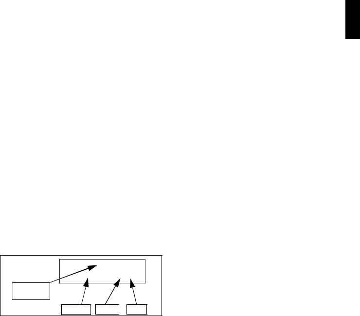
How to interpret the factory description
The factory description on the dataplate has the following meaning:
(1) |
|
(2) |
|
(3) |
|
(4) |
|
(5) |
(6) |
|
WT |
|
44 |
|
B |
|
R |
|
208 |
|
|
|
|
|
|
|
|
|||||
|
|
Description |
Possible variables |
|
|
|||||
(1) |
|
Mark |
WT ... |
|
|
|
|
|||
(2) |
|
Machine dimension |
44 = 44” 66 = 66” |
|
|
|||||
(3) |
|
Functional level |
B = Atmospheric plumbing circuit with boiler, |
|||||||
|
|
|
|
|
without CU |
|
|
|
|
|
|
|
|
|
|
C= Atmospheric plumbing circuit without |
|||||
|
|
|
|
|
boiler, without CU |
|
|
|||
(4) |
|
Rack loading |
L = from left to right |
|
|
|||||
|
|
|
|
|
R = from right to left |
|
|
|||
(5) |
|
Power supply |
208 = 208V 240= 240V |
|
|
|||||
|
|
voltage |
|
|
|
|
|
|
||
(6) |
|
|
|
|
|
|
|
|
|
|
A6 Copyright
This manual is intended for consultation only by the operator and can be given to third parties only with the written permission of Electrolux Professional S.p.A..
A7 Liability
The instructions supplied with the machine take into account the Electrolux Professional S.p.A. experience and knowledge acquired to date. The instructions are updated to the month and year given in the box located at the bottom right of the cover. The edition corresponds to the manual revision number. Every new edition replaces and cancels the previous ones.
DOC. NO. |
5956.583.01 |
|
|
|
01.2008 |
Number |
|
|
Document |
|
|
Edition |
Month |
Year |
Figure 5 Example of document and edition identification data.
The Manufacturer declines any liability for damage and malfunctioning caused by:
•non-compliance with the instructions contained in this manual;
•repairs not carried out in a workmanlike fashion, and replacements using spare parts different from those specified in this manual (the fitting and use of nonoriginal spare parts and accessories can negatively affect machine operation);
•operations by non-specialized technicians;
•unauthorized modifications or operations;
•inadequate maintenance;
•improper machine use;
•unexpected extraordinary events;
•use of the machine by uninformed and untrained personnel;
•non-application of the current provisions in the country of use, concerning safety, hygiene and health in the workplace.
The Manufacturer declines any liability for damage caused by arbitrary modifications and conversions carried out by the user or the Customer.
The employer or workplace manager is responsible for identifying and choosing adequate and suitable personal protection equipment to be worn by operators, in compliance with current regulations in the country of use.
Electrolux Professional S.p.A. declines any liability for possible inaccuracies contained in the manual, if due to printing or translation errors.
Any supplements to the instruction manual the Customer receives from the Manufacturer must be kept together with the manual, of which they will form an integral part.
A8 Keeping the manual
The manual must be carefully kept for the entire life of the machine until decommissioning.
The manual must stay with the machine in case of transfer, sale, hire, granting of use or leasing.
A9 Users of the manual
This manual is intended for:
•the carrier and handling personnel;
•installation and start-up personnel;
•the employer of machine users and the workplace manager;
•operators in charge of normal machine use;
•specialized technicians - technical assistance (see wiring diagram and service manual).
ENGLISH
9
B |
GENERAL DESCRIPTION OF MACHINE |
B1 General description
The rack-type dishwasher is suitable for washing dishes, glasses, cups, cutlery, trays, containers and receptacles in plastic and/or steel used for preparing, cooking and serving; as well as various cooking utensils in ceramic and/or metal. The machine is designed for the above-mentioned applications. Under no circumstances may the machine be used for other applications or ways not provided for in this manual.
This equipment has been produced to meet the needs for a better work environment and economical efficiency. These dishwashers are used in restaurants, cafeterias, cooking centres and large institutions.
The special dish racks, that can be equipped with various inserts, offer practical and easy use for obtaining excellent washing results. Rack handling inside the machine occurs automatically. The electronic system enables complete supervision of the washing process. The control panel also has a display that shows the operating parameters and signals any anomalies.
In this type of machine the rack is taken from the loading point to the unloading point, through the various washing functions. Systems for scraping and wetting the dishes (e.g. manual prewash spray) and areas for sorting and arranging them in the racks must be arranged ahead of the dishwasher.
The possible configurations of compact rack-type dishwashers, classified according to the maximum number of racks washed in one hour, are as follows:
|
|
|
|
|
|
|
|
|
|
|
|
|
|
|
44” |
|
|
|
|
|
|
|
|
|
|
|
|
|
66” |
|||||||||||||||||||
|
|
|
|
|
|
|
|
|
|
|
|
|
|
|
|
|
|
|
|
|
|
|
|
|
|
|
|
|
|
|
|
|
|
|
|
|
|
|
|
|
|
|
|
|
|
|
|
|
|
|
|
|
|
|
|
|
|
|
|
|
|
|
|
|
|
|
|
|
|
|
|
|
|
|
|
|
|
|
|
|
|
|
|
|
|
|
|
|
|
|
|
|
|
|
|
|
|
|
|
|
|
|
|
|
|
|
|
|
|
|
|
|
|
|
|
|
|
|
|
|
|
|
|
|
|
|
|
|
|
|
|
|
|
|
|
|
|
|
|
|
|
|
|
|
|
|
|
|
|
|
|
|
|
|
|
|
|
|
|
|
|
|
|
|
|
|
|
|
|
|
|
|
|
|
|
|
|
|
|
|
|
|
|
|
|
|
|
|
|
|
|
|
|
|
|
|
|
|
|
|
|
|
|
|
|
|
|
|
|
|
|
|
|
|
|
|
|
|
|
|
|
|
|
|
|
|
|
|
|
|
|
|
|
|
|
|
|
|
|
|
|
|
|
|
|
|
|
|
|
|
|
|
|
|
|
|
|
|
|
|
|
|
|
|
|
|
|
|
|
|
|
|
|
|
|
|
|
|
|
|
|
|
|
|
|
|
|
|
|
|
|
|
|
|
|
|
|
|
|
|
|
|
|
|
|
|
|
|
|
|
|
|
|
|
|
|
|
|
|
|
|
|
|
|
|
|
|
|
|
|
|
|
|
|
|
|
|
|
|
|
|
|
|
|
|
|
|
|
|
|
|
|
|
|
|
|
|
|
|
|
|
|
|
|
|
|
|
|
|
|
|
|
|
|
|
|
|
|
|
|
|
|
|
|
|
|
|
|
|
|
|
Figure 6 View of different configurations of compact rack-type dishwashers
B2 Description of machine modules
Rack-type dishwasher - 44” |
Rack-type dishwasher - 66” |
||||||||||||||||||||||
|
|
|
|
|
|
|
|
|
|
|
|
|
|
|
|
|
|
|
|
|
|
|
|
|
|
|
|
|
|
|
|
|
|
|
|
|
|
|
|
|
|
|
|
|
|
|
|
|
|
|
|
|
|
|
|
|
|
|
|
|
|
|
|
|
|
|
|
|
|
|
|
|
|
|
|
|
|
|
|
|
|
|
|
|
|
|
|
|
|
|
|
|
|
|
|
|
|
|
|
|
|
|
|
|
|
|
|
|
|
|
|
|
|
|
|
|
|
|
|
|
|
|
|
|
|
|
|
|
|
|
|
|
|
|
|
|
|
|
|
|
|
|
|
|
|
|
|
|
|
|
|
|
|
|
|
|
|
|
|
|
|
|
|
|
|
|
|
|
|
|
|
|
|
|
|
|
|
|
|
|
|
|
|
|
|
|
|
|
|
|
|
|
|
|
|
|
|
|
|
|
|
|
|
|
|
|
|
|
|
|
|
|
|
|
|
|
|
|
|
|
|
|
|
|
|
|
|
|
|
|
|
|
|
|
|
|
|
|
|
|
|
|
|
|
|
|
|
|
|
|
|
|
|
|
|
|
|
|
|
|
|
|
|
|
|
|
|
|
|
|
|
|
|
|
|
|
|
|
|
|
|
|
|
|
|
|
|
|
|
|
|
|
|
|
|
|
|
|
|
|
|
|
|
|
|
|
|
|
|
|
|
|
|
|
|
|
|
|
|
|
|
|
|
|
|
|
|
|
|
|
|
|
|
|
|
|
|
|
|
|
|
|
|
|
|
|
|
|
|
|
|
|
|
|
|
|
|
|
|
|
|
|
|
|
|
|
|
|
|
|
|
|
|
|
|
|
|
|
|
|
|
|
|
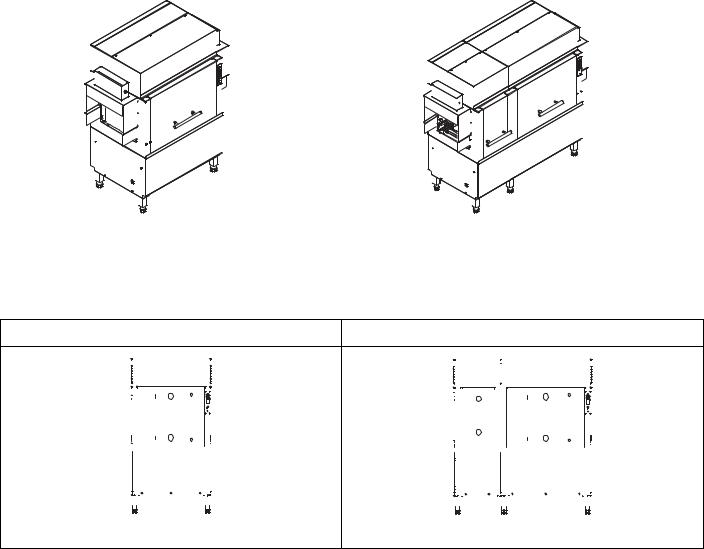
Wash + Rinse |
Prewash |
Wash + Rinse |
10

The machine consists of the following zones:
•wash zone
•rinse zone
and can be integrated with the following units:
•prewash zone
B2.1 Wash zone
Water with the addition of detergent is sprayed on the dishes in the wash zone through an upper and lower wash arm system. The purpose of this function is to remove all residuals of food from the dishes. Washing is carried out with water circulating at a temperature of 71-78 °C / 160-172 °F.
B2.2 Rinse zone
Water with the addition of rinse aid is sprayed on the dishes in the rinse zone through a system of arms equipped with special nozzles. The purpose of this function is to remove all residuals of detergent deriving from the previous wash phase.
Rinsing is carried out with clean water coming from the water system, heated to a max. temperature of 82-90 °C / 180194°F.
The high temperature ensures satisfactory drying and careful neutralization of bacteria. The addition of rinse aid allows the water to easily run off the dishes, thus favouring the drying process.
B2.3 Prewash zone
Water is sprayed on the dishes in the prewash zone through an upper and lower prewash arm system. The purpose of this function is to remove the larger food residuals, preparing the dishes for the subsequent wash phase.
Prewash is carried out with water circulating at a max. temperature of 40°C / 104°F in order to prevent food residuals (in particular proteins) from sticking to the dishes.
B2.4 View of module composition
In rack-type dishwashers the various zones just described are thus applied to the various previously defined configurations.
ENGLISH
11
C |
|
TECHNICAL DATA |
|
|
|
|||
C1 |
Main technical characteristics |
|
|
|
|
|
||
|
|
|
|
|
|
|
|
|
MODEL |
|
44” (208V) |
44” |
(240V) |
66” (208V) |
66” (240V) |
||
|
Power supply |
|
Electric |
Electric |
Electric |
Electric |
||
|
Power supply voltage |
V |
208 3PH |
240 3PH |
208 3PH |
240 3PH |
||
|
Frequency |
Hz |
60 |
60 |
|
60 |
60 |
|
|
Max. power. absorbed with boiler |
kW |
44.7 |
44.7 |
|
45.0 |
45.0 |
|
|
( rise 56 °C / 100 °F) |
|
|
|
|
|
|
|
|
Max. power. absorbed with boiler |
kW |
38.7 |
38.7 |
|
39.0 |
39.0 |
|
|
( rise 39 °C / 70 °F) |
|
|
|
|
|
|
|
|
Max. power. absorbed with boiler |
kW |
32.7 |
32.7 |
|
33.0 |
33.0 |
|
|
( rise 22 °C / 40 °F) |
|
|
|
|
|
|
|
|
Max. power. absorbed without boiler |
kW |
20.7 |
20.7 |
|
21.0 |
21.0 |
|
|
Max. current. absorbed with boiler |
A |
128.3 |
112.7 |
130.6 |
115.2 |
||
|
( rise 56 °C / 100 °F) |
|
|
|
|
|
|
|
|
Max. current. absorbed with boiler |
A |
111.6 |
98.3 |
|
113.9 |
100.8 |
|
|
( rise 39 °C / 70 °F) |
|
|
|
|
|
|
|
|
Max. current. absorbed with boiler |
A |
95.0 |
83.9 |
|
97.3 |
86.4 |
|
|
( rise 22 °C / 40 °F) |
|
|
|
|
|
|
|
|
Max. current. absorbed without boiler |
A |
61.7 |
55.0 |
|
64.0 |
57.5 |
|
|
Supply water pressure |
kPa/bar/PSI |
150..700 / 1.5..7 / |
150..700 / 1.5..7 / |
150..700 / 1.5..7 / |
150..700 / 1.5..7 / |
||
|
|
|
22..102 |
22..102 |
22..102 |
22..102 |
||
DATA |
Hot water supply temp. with boiler ** |
°C/°F |
27 / 80 |
27 / 80 |
27 / 80 |
27 / 80 |
||
( rise 56 °C / 100 °F) |
|
|
|
|
|
|
||
Hot water supply temp. with boiler |
°C/°F |
44 / 110 |
44 / 110 |
44 / 110 |
44 / 110 |
|||
|
||||||||
TECHNICAL |
( rise 39 °C / 70 °F) |
|
|
|
|
|
|
|
Hot water supply temp. with boiler |
°C/°F |
60 / 140 |
60 / 140 |
60 / 140 |
60 / 140 |
|||
|
||||||||
|
( rise 22 °C / 40 °F) |
|
|
|
|
|
|
|
|
Hot water supply temp. without boiler |
°C/°F |
90 / 194 |
90 / 194 |
90 / 194 |
90 / 194 |
||
MAIN |
Concentration of chlorides in water |
ppm |
< 20 |
< 20 |
|
< 20 |
< 20 |
|
Supply water hardness |
°fH /°dH/ |
14 / 8 / 140 |
14 / 8 / 140 |
14 / 8 / 140 |
14 / 8 / 140 |
|||
|
Electric conductivity of water |
μS/cm |
< 400 |
< 400 |
< 400 |
< 400 |
||
|
|
ppm CaCO3 |
|
|
|
|
|
|
|
Rack loading/feed |
RH machine |
From right to left |
From right to left |
From right to left |
From right to left |
||
|
|
LH machine |
From left to right |
From left to right |
From left to right |
From left to right |
||
|
No. speeds |
|
2 |
2 |
|
2 |
2 |
|
|
Capacity speed 1 |
racks/h |
100 |
100 |
|
100 |
100 |
|
|
Capacity speed 2 |
racks/h |
200 |
200 |
|
200 |
200 |
|
|
Water consumption |
l/h - gal/h |
300 - 79.3 |
300 - 79.3 |
315 - 83.2 |
315 - 83.2 |
||
|
Equivalent sound pressure level Leq |
dB(A) |
< 70 |
< 70 |
|
< 70 |
< 70 |
|
|
(1) |
|
|
|
|
|
|
|
|
Minimum Supply - Circuit Ampacity |
A |
67 |
58 |
|
67 |
58 |
|
|
Supply Terminal box ( Boiler ) (2) |
|
|
|
|
|
|
|
|
Minimum Supply - Circuit Ampacity |
A |
66 |
60 |
|
66 |
60 |
|
|
Supply Terminal box ( Machine ) (2) |
|
|
|
|
|
|
|
|
Maximum overcurrent protective device |
A |
80 |
70 |
|
80 |
70 |
|
|
Supply Terminal box ( Machine ) (2) |
|
|
|
|
|
|
|
|
Net weight |
lb/kg |
1012 / 459 |
1012 / 459 |
1268 / 575 |
1268 / 575 |
||
|
Shipping weight |
lb/kg |
- |
- |
|
- |
- |
|
|
Shipping width |
lb/kg |
- |
- |
|
- |
- |
|
|
Shipping height |
lb/kg |
- |
- |
|
- |
- |
|
|
Shipping depth |
lb/kg |
- |
- |
|
- |
- |
|
PREWASH |
tank capacity |
l/gal |
- |
- |
|
45/ 11.9 |
45/ 11.9 |
|
current absorbed by pump |
A |
- |
- |
|
2.5 |
2.5 |
||
|
temperature |
°C/°F |
- |
- |
|
max 40 / 104 |
max 40 / 104 |
|
|
pump delivery |
l/min - gal/min |
- |
- |
|
180 - 57.5 |
180 - 57.5 |
|
|
pump power |
kW |
- |
- |
|
0.37 |
0.37 |
|
|
tank heating element |
kW |
- |
- |
|
- |
- |
|
|
tank capacity |
l/gal |
100/ 26.4 |
100/ 26.4 |
100/ 26.4 |
100/ 26.4 |
||
WASH |
temperature |
°C/°F |
71..78 / 160..172 |
71..78 / 160..172 |
71..78 / 160..172 |
71..78/160..172 |
||
pump delivery |
l/min - gal/min |
450 - 118.9 |
450 - 118.9 |
450 - 118.9 |
450 - 118.9 |
|||
|
||||||||
|
pump power |
kW |
1.9 |
1.9 |
|
1.9 |
1.9 |
|
|
current absorbed by pumps |
A |
6.2 |
6.2 |
|
6.2 |
6.2 |
|
|
tank heating element |
kW |
9.0 + 9.0 |
9.0 + 9.0 |
9.0 + 9.0 |
9.0 + 9.0 |
||
12
RINSE |
|
|
44” (208V) |
44” |
(240V) |
66” (208V) |
66” (240V) |
|
ENGLISH |
||||
MODEL |
|
|
|
||||||||||
|
temperature |
°C/°F |
82..90 / 180..194 |
82..90 / 180..194 |
82..90 / 180..194 |
82..90/180..194 |
|
|
|||||
|
delivery |
l/min - gal/min |
5 - 1.32 |
|
5 - 1.32 |
|
5 - 1.32 |
|
5 - 1.32 |
|
|
|
|
|
pump power |
kW |
0.32 |
|
0.32 |
|
|
0.32 |
|
0.32 |
|
|
|
|
current absorbed by pump |
A |
1.5 |
|
1.5 |
|
|
1.5 |
|
1.5 |
|
|
|
|
boiler heating elements (with boiler |
kW |
6.0 + 6.0 |
+ 6.0 + 6.0 |
6.0 + 6.0 |
+ 6.0 + 6.0 |
6.0 + 6.0 |
+ 6.0 + 6.0 |
6.0 + 6.0 |
+ 6.0 + 6.0 |
|
|
|
|
|
||||||||||||
|
rise 100) |
|
|
|
|
|
|
|
|
|
|
|
|
|
boiler heating elements (with boiler |
kW |
6.0 + 6.0 |
+ 6.0 |
6.0 + 6.0 |
+ 6.0 |
6.0 + 6.0 |
+ 6.0 |
6.0 + 6.0 |
+ 6.0 |
|
|
|
|
rise 70) |
|
|
|
|
|
|
|
|
|
|
|
|
|
boiler heating elements (with boiler |
kW |
6.0 + 6.0 |
|
6.0 + 6.0 |
|
6.0 + 6.0 |
|
6.0 + 6.0 |
|
|
|
|
|
rise 40) |
|
|
|
|
|
|
|
|
|
|
|
|
|
boiler capacity |
l/ gal |
12+12 / |
3.17+ 3.17 |
12+12 / |
3.17+ 3.17 |
12+12 / |
3.17+ 3.17 |
12+12 / |
3.17+ 3.17 |
|
|
|
Table 1 Main technical characteristics, performance and consumption
** If the water supply temperature is lower than the value indicated, the machine could not comply with NSF/ ANSI 3 2003.
(1)The value could increase depending on the work station where measured.
(2)See Figure 10 ( Electrical connections diagram ).
C2 Characteristics of power supply
The AC power supply to the machine must meet the following conditions:
•max. voltage variation ± 6% continuous ± 10% for a short period.
•max. frequency variation ± 1% continuous ± 2% for a short period.
Harmonic distorsion, unbalanced three-phase supply voltage, voltage pulses, interruption, dips and the other electric characteristics must respect the provisions of point 4.3.2 of Standard EN 60204-1 (IEC 60204-1).
IMPORTANT!
The machine’s power supply must be protected against overcurrents (short circuits and overloads) by fuses or suitable thermal magnetic circuit breakers.
IMPORTANT!
The dishwasher shall be installed in accordance with local codes, or in the absence of local codes, installed in accordance with the applicable requirements in the National Electrical Code, NFPA 70, Canadian Electrical Code (CEC), Part 1, CSA C22.1, and Standard for Ventilation Control and Fire Protection of Commercial Cooking Operations, NFPA 96.
IMPORTANT!
Customers are requested to follow these instructions, otherwise the Manufacturer does not guarantee the machine for continuous operation and/or against faults.
13

D |
TRANSPORT, HANDLING AND STORAGE |
D1 Introduction
Transport (i.e. transfer of the machine from one place to another) and handling (i.e. transfer inside workplaces) must occur with the use of special equipment of adequate capacity.
The machine can be transported by road, rail, sea or air. Except for transport by road, the machine is placed inside a container in which there are also other machines. The machines can be positioned inside the container by the Manufacturer or by the carrier.
IMPORTANT!
Due to its size, during transport one machine cannot be stacked on top of another, therefore possible risks of load overturning are excluded.
The Manufacturer declines any liability for possible damage to the packing and the machine.
On receiving the machine, check that the packing and components are not damaged. In case of damage, immediately notify the carrier and the Manufacturer.
If the equipment received has visible or hidden damage, a claim can be made with the carrier.
Visible losses or damage must be reported in the transport document at the time of delivery. The transport document must be signed by the carrier’s representative (e.g. the driver). If the transport document is not signed, the carrier can reject the claim.
The request for inspection must be submitted to the carrier within 15 days in case of non-visible damage or losses detected only after unpacking the equipment. The carrier shall arrange an inspection. Keep all the packing material and contents. Under no circumstances may a damaged appliance be returned to the manufacturer without prior notice and written permission.
The machine must only be transported, handled and stored by qualified personnel, who must have:
-specific technical training and experience;
-knowledge of the safety regulations and applicable laws in the relevant sectors;
-knowledge of the general safety provisions;
-the ability to recognize and avoid any possible hazard.
The Manufacturer declines any liability whenever transport is undertaken by carriers chosen by the Customer.
IMPORTANT!
Machine transport, handling and storage personnel must receive adequate instruction and training on the use of lifting systems and the use of personal protection equipment suitable for the type of operation performed (e.g. overalls, safety shoes, gloves and helmet).
D1.1 Transport: Instructions for the carrier
During the journey the tightness of the fixing systems must be checked several times, and in particular:
•just a few km after the start of the journey;
•in case of sudden temperature changes;
•in case of intense cold;
•in case of particularly rough roads.
When removing the anchoring systems, make sure the stability of the machine parts does not depend on the anchoring and, therefore, that this operation does not cause the load to fall off the vehicle.
WARNING!
Do not stand under suspended loads during the loading/unloading phases. Unauthorized personnel must not access the work zone.
IMPORTANT!
The machine’s weight alone is not sufficient to keep it steady.
The transported load can shift:
-when braking;
-when accelerating;
-in corners;
-on particularly rough roads.
If slings in synthetic fibre are used to anchor the machines, protect them from friction, abrasion and damage caused by possible sharp edges of the load. If there are sharp edges that can damage the sling, use suitable corner protectors or sliding tubes.
CAUTION!
When removing the anchoring systems, make sure the stability of the machine parts does not depend on the anchoring and, therefore, that this operation does not cause the load to fall off the vehicle. Before unloading the machine components make sure all the anchoring systems are removed.
14
 Loading...