


Installation Instructions
Electrolux Front-Load Gas & Electric Dryer
Instrucciones de Instalacion
Secadora eléctrica y a gas de carga frontal Electrolux
Instructions d’installation
Sécheuse à gaz et à l’électricité à chargement frontal Electrolux
137018200 A (0801)
2 |
Finding Information |
|
|
Please read and save this guide
Thank you for choosing Electrolux, the new premium brand in home appliances. These Installation Instructions are part of our commitment to customer satisfaction and product quality throughout the life of your new appliance.
We view your purchase as the beginning of a relationship. To ensure our ability to continue serving you, please use this page to record important product information.
Keep a record for quick reference
Purchase date
Electrolux model number
Electrolux serial number
 NOTE
NOTE
Registering your product with Electrolux enhances our ability to serve you. You can register online at www.electroluxappliances.com or by dropping your Product Registration Card in the mail.
Questions?
For toll-free telephone support in the U.S. and Canada: 1-877-4ELECTROLUX (1-877-435-3287)
For online support and product information visit http://www.electroluxappliances.com
Table of contents
Finding information......................................................... |
2 |
|
SAFETY........................................................................... |
3 |
|
• |
Pre-installation requirements...................................... |
3 |
Installation requirements.............................................. |
4-9 |
|
• |
Electrical system requirements................................... |
4 |
• Gas supply requirements............................................ |
5 |
|
• Exhaust system requirements.................................. |
5-7 |
|
• |
Mobile home installation............................................. |
7 |
• |
Clearance requirements.............................................. |
8 |
• |
Installed dimensions.................................................... |
9 |
Installation.Instructions............................................ |
10-18 |
|
• |
Electrical installation.................................................. |
10 |
• |
Grounding requirements - Electric dryer (USA)......... |
10 |
• |
Grounding requirements - Electric dryer (Canada).... |
11 |
|
• Grounding requirements - Gas dryer........................ |
|
11 |
|
• |
Electrical connection - Electric dryer (3-wire cord)... |
12 |
|
• |
Electrical connection - Electric dryer (4-wire cord)... |
13 |
|
• Gas connection......................................................... |
|
14 |
|
• Water connection (Steam Model only)................. |
15-16 |
||
• |
General installation.................................................... |
|
17 |
• |
Performing installation cycle..................................... |
|
18 |
Reversing door......................................................... |
19-24 |
||
Options......................................................................... |
|
25 |
|
• |
Accessories............................................................... |
|
25 |
• Replacement parts.................................................... |
|
25 |
|
Notes............................................................................. |
|
26 |
|
©2008 Electrolux Major Appliances |
All rights reserved. |
Safety 3
Important Safety Instructions
Recognize safety symbols, words and labels
Safety items throughout this manual are labeled with a WARNING or CAUTION based on the risk type as described below:
This symbol alerts you to situations that may cause serious body harm, death or property damage.
This symbol alerts you to situations that may cause bodily injury or property damage.
Read all of the following instructions before installing and using this appliance:
•Destroy the carton and plastic bags after the dryer is unpacked. Children might use them for play. Cartons covered with rugs, bedspreads, or plastic sheets can become airtight chambers causing suffocation. Place all materials in a garbage container or make materials inaccessible to children.
•Clothes dryer installation and service must be performed by a qualified installer, service agency or the gas supplier.
•Install the clothes dryer according to the manufacturer’s instructions and local codes.
•The electrical service to the dryer must conform with local codes and ordinances and the latest edition of the National Electrical Code, ANSI/
NFPA 70, or in Canada, the Canadian electrical code C22.1 part 1.
•The gas service to the dryer must conform with local codes and ordinances and the latest edition of the National Fuel Gas Code ANSI Z223.1,
or in Canada, CAN/ACG B149.1-2000.
•The dryer is designed under ANSI Z 21.5.1 or ANSI/UL 2158 - CAN/CSA C22.2 No. 112 (latest editions) for HOME USE only. This dryer is not recommended for commercial applications such as restaurants, beauty salons, etc.
•The instructions in this manual and all other literature included with this dryer are not meant to cover every possible condition and situation that may occur. Good safe practice and caution MUST be applied when installing, operating and maintaining any appliance.
WARNING
For your safety the information in this manual must be followed to minimize the risk of fire or explosion or to prevent property damage,
personal injury or loss of life. Do not store or use gasoline or other flammable vapors and liquids in the vicinity of this or any other appliance.
WHAT TO DO IF YOU SMELL GAS:
•Do not try to light any appliance.
•Do not touch any electrical switch; do not use any phone in your building.
•Clear the room, building or area of all occupants.
•Immediately call your gas supplier from a neighbor’s phone. Follow the gas supplier’s instructions.
•If you cannot reach your gas supplier, call the fire department.
Save these instructions for future reference.
Pre-installation requirements
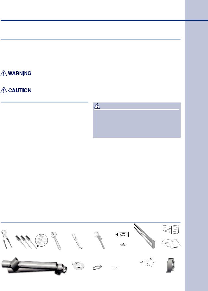
Tools and materials needed for installation:
 or or
or or 
Adjustable |
|
Phillips, straight, & |
Adjustable |
Universal wrench |
Pipe wrench |
LP-resistant |
Carpenter’s level |
External |
|||||||
pliers |
square bit screwdrivers |
wrench |
supplied with |
for gas |
|
thread tape |
|
|
|
|
|
vent hood |
|||
|
|
|
|
|
matching washer |
supply |
|
(for natural gas |
|
|
|
|
|
|
|
|
|
|
|
|
|
|
|
|
|
|
|
||||
|
|
|
|
|
|
|
|
or LP supply) |
|
|
|
|
|
|
|
|
|
|
|
|
|
|
|
|
|
|
|
|
|
||
|
|
|
|
|
3-wire or 4-wire |
4 in. |
|
gas line |
½” NPT union flare |
|
|||||
|
|
|
4 inch, rigid metal or |
|
|
adapters (x2) and |
Metal foil tape |
||||||||
|
|
|
|
|
|||||||||||
|
|
|
|
240 volt cord kit |
(10.2 cm) |
shutoff valve |
flexible gas supply line |
||||||||
|
semi-rigid metal exhaust duct work |
(electric dryer) |
clamp |
(gas dryer) |
|
(gas dryer) |
(not duct tape) |
||||||||
|
|
|
|
|
|
|
|
|
|
|
|
|
|
|
|
4 |
Installation Requirements |
|
|
Electrical system requirements
NOTE
Because of potentially inconsistent voltage capabilities, the use of this dryer with power created by gas powered generators, solar powered generators, wind powered generators or any other generator other than the local utility company is not recommended.
Electrical requirements for electric dryer:
CIRCUIT - Individual 30 amp. branch circuit fused with 30 amp. time delay fuses or circuit breakers. Use separately fused circuits for washer and dryer. DO NOT operate a washer and a dryer on the same circuit.
POWER SUPPLY - 3-wire or 4-wire, 240 volt, single phase, 60 Hz, Alternating Current.
IMPORTANT
This dryer is internally grounded to neutral unless it was manufactured for sale in Canada. Grounding through the neutral link is prohibited for: (1) new branch circuit installations, (2) mobile homes, (3) recreational vehicles, and (4) areas where local codes do not permit grounding through the neutral.
3-WIRE POWER SUPPLY CORD KIT (not supplied)
3-wire receptacle
(NEMA type 10-30R)
The dryer MUST employ a 3-conductor power supply cord NEMA 10-30 type SRDT rated at
240 volt AC minimum, 30 amp, with 3 open end spade lug connectors with upturned ends or closed loop connectors and marked for use
with clothes dryers. For 3-wire cord connection instructions see ELECTRICAL CONNECTIONS
FOR A 3-WIRE SYSTEM.
4-WIRE POWER SUPPLY CORD KIT (not supplied)
4-wire receptacle
(NEMA type 14-30R)
The dryer MUST employ a 4-conductor power supply cord NEMA 14-30 type SRDT or ST (as required) rated at 240 volt AC minimum, 30 amp, with 4 open end spade lug connectors with upturned ends or closed loop connectors and marked for use with clothes dryers. For 4-wire cord connection instructions see ELECTRICAL
CONNECTIONS FOR A 4-WIRE SYSTEM.
NOTE
Dryers manufactured for sale in Canada have factory-installed, 4-wire power supply cord
(NEMA 14-30R).
OUTLET RECEPTACLE - NEMA 10-30R or NEMA
14-30R receptacle to be located so the power supply cord is accessible when the dryer is in the installed position.
GROUNDING CONNECTION - See “Grounding requirements” in Electrical Installation section.
Electrical requirements for gas dryer:
CIRCUIT - Individual, properly polarized and grounded 15 amp. branch circuit fused with 15 amp. time delay fuse or circuit breaker.
POWER SUPPLY - 2-wire, with ground, 120 volt, single phase, 60 Hz, Alternating Current.
POWER SUPPLY CORD - The dryer is equipped with a 120 volt 3-wire power cord.
GROUNDING CONNECTION - See “Grounding requirements” in Electrical Installation section.
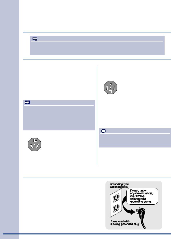
Grounding type wall receptacle
Do not, under
any circumstances, cut, remove,
or bypass the grounding prong.
Power cord with 3-prong grounded plug
Installation Requirements |
5 |
|
|
Gas supply requirements
WARNING
EXPLOSION HAZARD
Uncoated copper tubing will corrode when subjected to natural gas, causing gas leaks.
Use ONLY black iron, stainless steel, or plasticcoated brass piping for gas supply.
1.Installation MUST conform with local codes, or in the absence of local codes, with the National
Fuel Gas Code, ANSI Z223.1 (latest edition).
2.The gas supply line should be 1/2 inch (1.27 cm) pipe.
3.If codes allow, flexible metal tubing may be used to connect your dryer to the gas supply line. The tubing MUST be constructed of stainless steel or plastic-coated brass.
4.The gas supply line MUST have an individual shutoff valve.
5.A 1/8 inch (0.32 cm) N.P.T. plugged tapping, accessible for test gauge connection, MUST be installed immediately upstream of the gas supply connection to the dryer.
6.The dryer MUST be disconnected from the gas supply piping system during any pressure testing of the gas supply piping system at test pressures in excess of 1/2 psig (3.45 kPa).
7.The dryer MUST be isolated from the gas supply piping system during any pressure testing of the gas supply piping system at test pressures equal to or less than 1/2 psig (3.45 kPa).
8.Connections for the gas supply must comply with the Standard for Connectors for Gas Appliances, ANSI Z21.24.
Exhaust system requirements
Use only 4 inch (10.2 cm) diameter (minimum) rigid or flexible metal duct and approved vent hood which has a swing-out damper(s) that open when the dryer is in operation. When the dryer stops, the dampers automatically close to prevent drafts and the entrance of insects and rodents. To avoid restricting the outlet, maintain a minimum of 12 inches (30.5 cm) clearance between the vent hood and the ground or any other obstruction.
WARNING
FIRE HAZARD
Failure to follow these instructions can create excessive drying times and fire hazards.
The following are specific requirements for proper and safe operation of your dryer.
WARNING
FIRE HAZARD
Do not install a clothes dryer with flexible plastic or metal foil venting materials. Flexible venting materials are known to collapse, be easily crushed and trap lint. These conditions will obstruct clothes dryer airflow and increase the risk of fire.
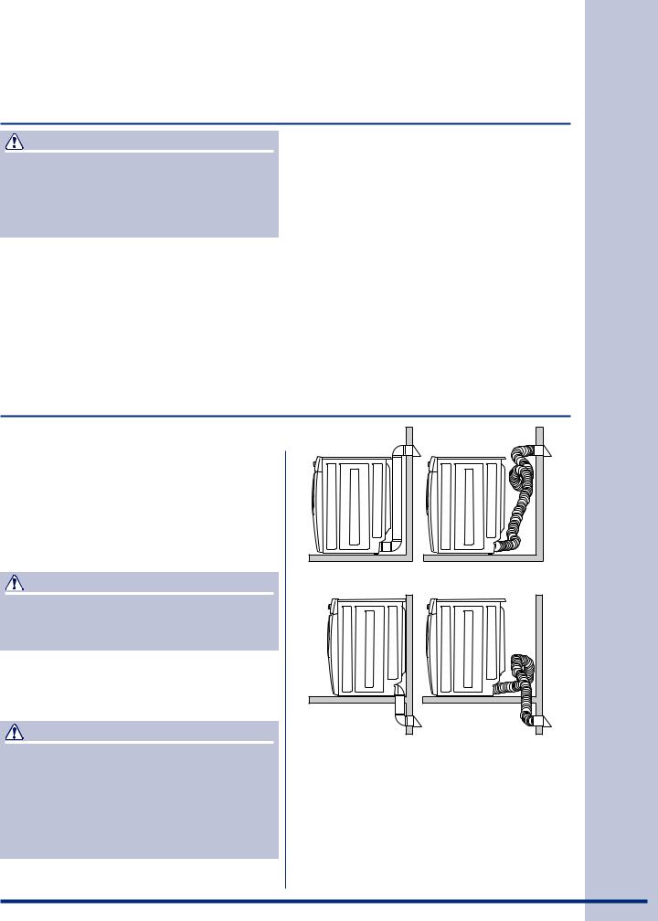
Correct |
Incorrect |
Correct |
Incorrect |
If your present system is made up of plastic duct or metal foil duct, replace it with a rigid or semi-rigid metal duct. In Canada and the United
States if metal (foil type) duct is installed, it must be of a specific type identified by the appliance manufacturer as suitable for use with clothes dryers and in the United States must also comply with the Outline for Clothes Dryer Transition Duct, UL standard 2158A. Also, ensure the present duct is free of any lint prior to installing dryer duct.

6 |
Installation Requirements |
|
|
|
Exhaust system requirements, continued |
|
|
WARNING
FIRE HAZARD
A clothes dryer must be exhausted outdoors. Do not exhaust dryer into a chimney, a wall, a ceiling, an attic, a crawl space or any concealed space of a building. A clothes dryer produces combustible lint. If the dryer is not exhausted outdoors, some fine lint will be expelled into the laundry area. An accumulation of lint in any area of the home can create a health and fire hazard.
The dryer must be connected to an exhaust outdoors. Regularly inspect the outdoor exhaust opening and remove any accumulation of lint around the outdoor exhaust opening and in the surrounding area.
WARNING
FIRE HAZARD
•Do not allow combustible materials (for example: clothing, draperies/curtains, paper) to come in contact with exhaust system. The dryer MUST NOT be exhausted into a chimney, a wall, a ceiling, or any concealed space of a building which can accumulate lint, resulting in a fire hazard.
•Do not screen the exhaust ends of the vent system, or use any screws, rivets or other fasteners that extend into the duct to assemble the exhaust system. Lint can become caught in the screen, on the screws or rivets, clogging the duct work and creating a fire hazard as well as increasing drying times. Use an approved vent hood to terminate the duct outdoors, and seal all joints with duct tape. All male duct pipe fittings MUST be installed downstream with the flow of air.
WARNING
FIRE HAZARD
Exceeding the length of duct pipe or number of elbows allowed in the “MAXIMUM LENGTH” charts can cause an accumulation of lint in the exhaust system. Plugging the system could create a fire hazard, as well as increase drying times.
|
|
MAXIMUM LENGTH |
|
Number |
of 4” (10.2cm) Rigid Metal Duct |
||
|
VENT HOOD TYPE |
|
|
|
(Preferred) |
|
|
90° of |
|
|
|
turns |
|
|
2.5” |
4” |
|
|
|
(10.2cm) |
louvered |
(6.35cm) |
|
0 |
125 ft. (38.10m) |
110 ft. (33.53m) |
|
1 |
115 ft. (35.05m) |
100 ft. (30.48m) |
|
2 |
105 ft. (32.00m) |
90 ft. (27.43m) |
|
3 |
95 ft. (28.96m) |
80 ft. (24.38m) |
|
4 |
85 ft. (25.91m) |
70 ft. (21.34m) |
|
|
|
MAXIMUM LENGTH |
|
of 4” (10.2cm) Semi-Rigid Metal Duct |
|||
Number |
|
VENT HOOD TYPE |
|
|
(Preferred) |
|
|
90° of |
|
|
|
turns |
|
|
2.5” |
4” |
|
|
|
(10.2cm) |
louvered |
(6.35cm) |
|
0 |
60 ft. (18.29m) |
45 ft. (13.72m) |
|
1 |
50 ft. (15.24m) |
35 ft. (10.67m) |
|
2 |
40 ft. (12.19m) |
25 ft. (7.62m) |
|
3 |
|
NOT RECOMMENDED |
|
Install male fittings in correct direction:
In installations where the exhaust system is not described in the charts, the following method must be used to determine if the exhaust system is acceptable:
CORRECT INCORRECT
|
Installation Requirements |
7 |
||||
|
|
|
|
|
||
Exhaust system requirements, continued |
|
|||||
|
|
|
|
|
|
|
|
|
|
• Compression or crimping of the exhaust system |
|
||
|
WARNING |
|
||||
|
|
|
will cause an increase in vent restriction. |
|
||
|
EXPLOSION HAZARD |
|
|
|
||
|
|
• The exhaust system should be inspected and |
|
|||
Do not install the dryer where gasoline or other |
|
|
cleaned a minimum of every 18 months with |
|
||
flammables are kept or stored. If the dryer is |
|
|
normal usage. The more the dryer is used, |
|
||
installed in a garage, it must be a minimum of 18 |
|
|
the more often you should check the exhaust |
|
||
inches (45.7 cm) above the floor. Failure to do so |
|
|
system and vent hood for proper operation. |
|
||
can result in death, explosion, fire or burns. |
|
|
|
|
|
|
1. |
Connect an inclined or digital manometer |
|
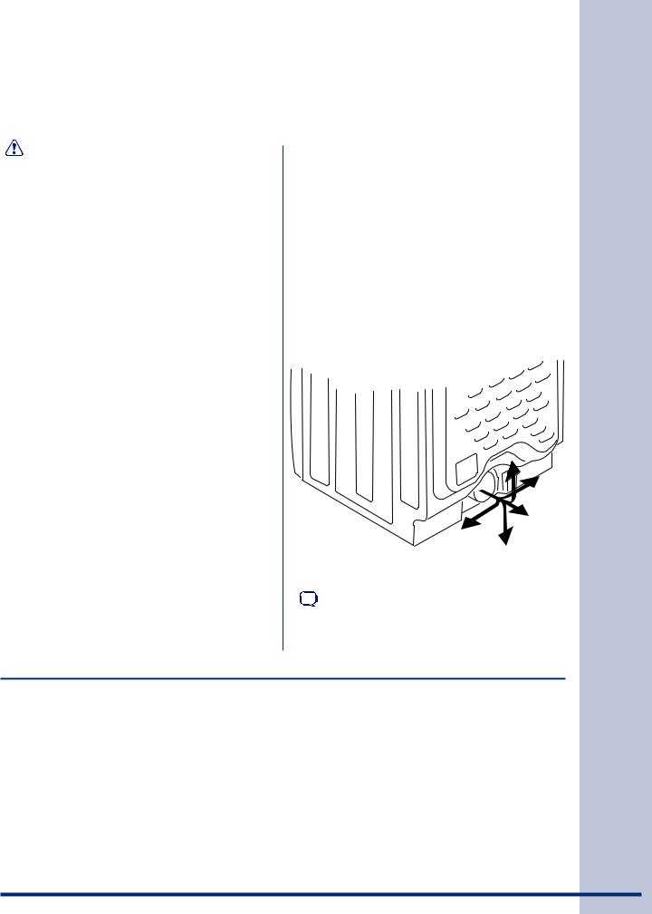
Exhaust direction |
|
||
|
between the dryer and the point the exhaust |
|
Directional exhausting can be accomplished by |
|
||
|
connects to the dryer. |
|
installing a quick-turn 90° dryer vent elbow directly |
|
||
2. |
Set the dryer timer and temperature to air fluff |
|
to exhaust outlet of dryer. Dryer vent elbows are |
|
||
|
available through your local parts distributor or |
|
||||
|
(cool down) and start the dryer. |
|
|
|||
|
|
hardware store. |
|
|||
3. |
Read the measurement on the manometer. |
|
|
|||
|
|
|
|
|
||
4. |
The system back pressure MUST NOT be |
|
|
|
|
|
|
higher than 1.0 inch of water column. If the |
|
|
|
|
|
|
system back pressure is less than 1.0 inch of |
|
|
|
|
|
|
water column, the system is acceptable. If the |
|
|
|
|
|
|
manometer reading is higher than 1.0 inch of |
|
|
|
|
|
|
water column, the system is too restrictive and |
|
|
|
|
|
|
the installation is unacceptable. |
|
|
|
|
|
Although vertical orientation of the exhaust system |
|
|
|
|
|
|
is acceptable, certain extenuating circumstances |
|
|
|
|
|
|
could affect the performance of the dryer: |
|
|
|
|
|
|
• |
Only the rigid metal duct work should be used. |
|
|
|
|
|
• |
Venting vertically through a roof may expose |
|
See also CLEARANCE REQUIREMENTS on the |
|
||
|
the exhaust system to down drafts causing an |
|
|
|||
|
|
next page. |
|
|||
|
increase in vent restriction. |
|
|
|||
|
|
|
|
|
|
|
|
|
|
|
|
|
|
• |
Running the exhaust system through an |
|
|
|
NOTE |
|
|
uninsulated area may cause condensation and |
|
Use of 90° quick-turn elbow required to meet |
|
||
|
faster accumulation of lint. |
|
|
|||
|
|
minimum installation depth. |
|
|||
|
|
|
|
|||
|
|
|
|
|
|
|
Manufactured or mobile home installation
1.Installation MUST conform to current Manufactured Home Construction & Safety Standard, Title 24 CFR, Part 32-80 (formerly the Federal Standard for Mobile Home Construction and Safety, Title 24, HUD Part 280) or Standard CAN/CSAZ240 MH.
2.Dryer MUST be exhausted outside (outdoors, not beneath the mobile home) using metal ducting that will not support combustion. Metal ducting must be 4 inches (10.16 cm) in diameter with no obstructions. Rigid metal duct is preferred.
3.If dryer is exhausted through the floor and area beneath the mobile home is enclosed,
the exhaust system MUST terminate outside the enclosure with the termination securely fastened to the mobile home structure.
4.Refer to previous sections in this guide for other important exhaust venting system requirements.
5.When installing a gas dryer into a mobile home, a provision must be made for outside make up air. This provision is to be not less than twice the area of the dryer exhaust outlet.
6.Installer MUST anchor this (1) dryer or (2) dryer mounted on pedestal to the floor with approved
Mobile Home Installation Kit - P/N 137067200.
8 |
Installation Requirements |
|
|
|
Clearance requirements |
|
|
IMPORTANT
DO NOT INSTALL YOUR DRYER:
1.In an area exposed to dripping water or outside weather conditions.
2.In an area where it will come in contact with curtains, drapes, or anything that will obstruct the flow of combustion and ventilation air.
3.On carpet. Floor MUST be solid with a maximum slope of 1 inch (2.54 cm).
INSTALLATION IN A RECESS OR CLOSET
1.A dryer installed in a bedroom, bathroom, recess or closet, MUST be exhausted outdoors.
2.No other fuel burning appliance shall be installed in the same closet as the gas dryer.
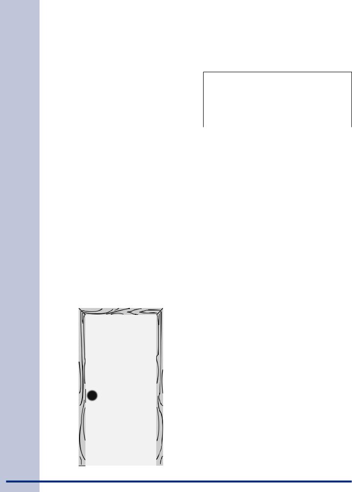
3.Your dryer needs the space around it for proper ventilation.
DO NOT install your dryer in a closet with a solid door.
4.Closet door ventilation required: A minimum of 120 square inches (774.2 cm²) of opening, equally divided at the top and bottom of the door, is required. Openings should be located
3 inches (7.6 cm) from bottom and top of door.
Openings are required to be unobstructed when a door is installed. A louvered door with equivalent air openings for the full length of the door is acceptable.
 3” (7.6cm)
60 sq. in. (387.1cm²)
60 sq. in. (387.1cm²)
 3” (7.6cm)
closet door
MINIMUM INSTALLATION CLEARANCES - Inches (cm)
|
SIDES |
REAR |
TOP |
FRONT |
|
|
|
|
|
Alcove |
0” (0 cm) |
0” (0 cm)* |
0” (0 cm) |
n/a |
|
|
|
|
|
Under- |
0” (0 cm) |
0” (0 cm)* |
0” (0 cm) |
n/a |
Counter |
|
|
|
|
Closet |
0” (0 cm) |
0” (0 cm)* |
0” (0 cm) |
1” (2.54 cm) |
|
|
|
|
|
*For other than straight back venting, a quick-turn 90° dryer vent elbow must be installed to achieve 0” (0 cm) installation.
0” 
 (0cm)
(0cm)
0”
(0cm)
1” |
0” |
(2.54cm) |
(0cm) |
NOTE
To achieve an installation with 0” (0 cm) clearance for the back of the dryer (for other than straight back venting), a quick-turn 90° dryer vent elbow must be installed as described previously in this manual.
 Loading...