


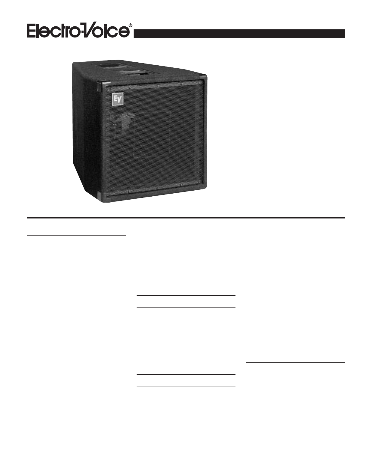
MTH-1
MTH-1
Biampable,
Mid/High Coaxial Module
Speaker System
• Two-way mid/high horn-loaded
system
• 350-watt long-term power capacity
• Rotatable coaxial mid/high section
• Rugged, road-ready cabinet; metal
grille; black carpet finish
• High "Q" system for increased
intelligibility
• Neutrik Speakon
®
inputs
• Biampable
• When combined with the MLT-1 or
MTL-1X, forms an MT-1 system
which is a highly efficient and
compact system
Description
The Electro-Voice MTH-1 is a 350-watt,
two-way, constant directivity horn-loaded,
high-efficiency main loudspeaker system.
The system may be biamplified or used full
range with the internal passive crossover.
The MTH-1 mid/high module, combined
with an MTL-1 or MTL-1X low-frequency
system, forms a high-output sound reinforce-
ment for a club, large hall, or outdoor events
in a compact package which can be used eas-
ily by a two-person crew.
The 60° x 40° high- and mid-frequency horns
are coaxially mounted and are easily rotated
together, allowing the horizontal and verti-
cal coverage patterns to be interchanged. The
high “Q” pattern gives increased intelligi-
bility. Combined with the trapezoidal enclo-
sure, the high “Q” and rotatable horns give
many options in placing this versatile enclo-
sure in tight spaces.
The high-frequency section operates above
1,600 Hz. The DH2T compression driver is
coupled to the HP64M 60° x 40° constant-
directivity horn for smooth and extended
high-frequency performance to 16,000 Hz.
The HP64M is a polypropylene horn with ex-
ceptional strength and performance. The
horn/driver combination is securely mounted
to the mid horn by a heavy-duty steel bracket.
The mid-frequency section operates between
160 Hz and 1,600 Hz. This horn-loaded sec-
tion uses a DL10X. A proprietary phase plug
(U.S. Patent No. 4,718,517) is used to ex-
tend the high-end output and blend
seamlessly into the coaxial high-frequency
section.
Crossover
To optimize performance with a low-fre-
quency system, such as the MTL-1, the
MTH-1 should be used in conjunction with
an active crossover with a minimum slope
of 12-dB-per-octave and a crossover fre-
quency of 160 Hz. Due to the high efficiency
of the MTH-1, less amplifier input is needed
to achieve a given sound output level.
Biamping
The MTH-1 can be biamped by removing the
input panel and following the instructions
given. The usable frequency ranges for the
individual sections are 125-2,000 Hz for the
mid-frequency band and 1,200-16,000 Hz for
the high-frequency band. Minimum cross-
over slopes of 12-dB-per-octave are recom-
mended. A protection capacitor with a 3-dB-
down point of 1,100 Hz is in included in the
high-frequency section when in biamp mode.
The usable frequency response of the over-
all biamped system is 125-16,000 Hz, the
same response that is expected with the pas-
sive setup. For maximum performance of the
MTH-1 in a full-range application, the addi-
tion of the MTL-1 low-frequency loud-
speaker system is recommended. This com-
bination forms the MT-1 full-range high-
level sound-reinforcement system. For use
as an MT-1 system, the Electro-V oice's Dx34
Digital Signal Processing unit or XEQ-3
electronic crossover/equalizer/time delay unit
with the EQMT1 plug-in modules may be
used for crossing over the two sections.
Amplifier Power recommendations
As noted in the Power-Handling section,
below, the MTH-1 has a random-noise power
capacity of 350-watts long term (1,400 watts
peak) per EIA RS-426-A 1980. The follow-
ing guidelines will help relate this to an ap-
propriate power amplifier output rating.
1. To use the MTH-1 to full capacity,
skilled experts in sound system installation
and operation will obtain the best results if
the power amplifier is 2.0 to 4.0 times the
long-term average noise power rating of the

MTH-1 Biampable, Mid/High Coaxial Module Speaker System
MTH-1 Biampable, Mid/High Coaxial Module Spealer System
2
speaker system. For the MTH-1, this is 700
to 2,800 watts.
The caution cannot be made strongly
enough, however, that this arrangement
is only for experts or those who can disci-
pline themselves against “pushing” the
system for ever-higher sound levels and
who can avoid “accidents” such as cata-
strophic feedback or dropped micro-
phones.
2. A more conservative, “normal” ampli-
fier size, which will produce audible results
nearly equal to those of the “expert” recom-
mendation, is 1.0 to 1.4 times the long-term
average noise power rating of the speaker.
For the MTH-1, this is 350 to 490 watts.
3. To be very conservative, one can use an
amplifier rated at 0.5 to 0.7 times the long-
term average noise power rating of the loud-
speaker. For the MTH-1, this is 175 to 245
watts.
Request P.A. Bible Addition No. Two
(“Power- Handling Capacity”) for more
background on these recommendations.
Speaker Protection
A self-resetting high-frequency protection
circuit, Electro-Voice's PRO
™
circuit, is in-
cluded in the MTH-1 to prevent against ac-
cidental overdrive and improve reliability. If
the input power to the high-frequency driver
exceeds the nominal rating, the protection
circuit is activated and reduces the power
delivered to the driver. The system will re-
main in this mode of operation until the in-
put power is reduced to a safe level.
Frequency Response
The MTH-1’s axial frequency response was
measured in Electro-Voice’s large anechoic
chamber at a distance of 3 meters (10 feet)
with a swept sine-wave input. Figure 2 has
been averaged and corrected for 1 watt at 1
meter.
Enclosure Construction
Intended to be used as a portable speaker sys-
tem, the MTH-1 is ruggedly constructed of
3/4-inch, void-free plywood. All joints are
dado cut, and the cabinet is finished with a
densely-woven, abuse-resistant carpet that is
both attractive and highly durable. A full-
length steel grille protects the system from
damage. Large, heavy-duty metal corner pro-
tectors, firmly secured rubber feet, and re-
cessed handles complete the picture, ensur-
ing that the MTH-1 speaker system is ide-
ally suited for a long and reliable life on the
road.
MTH-1 Connections
The MTH-1 is equipped with two paralleled
Neutrik Speakon
®
NL4MD-V connectors,
selected for their ability to reliably deliver to
the speaker components the high currents
delivered by high-wattage power amplifiers.
The NL4FC is a four-pin mating connector
for the NL4MD-V, and Figure 5 shows how
the usual two-conductor speaker cable
should be wired to pins 1+ and 1– of the con-
nector. Two typical connectors at the power
amplifier end of the cable are shown: banana
and 1/4-inch phone plugs. (The banana plug
provides the more reliable connection.)
Full-range pin arrangements are:
1– = IN (–)
1+ = IN (+)
2– = Not Used
2+ = Not Used
Biamp pin arrangements are:
1– = MB (–)
1+ = MB (+)
2– = HF (–)
2+ = HF (+)
To find your local Neutrik dealer, contact:
Neutrik USA, Inc.
195-S3 Lehigh Ave.
Lakewood, NJ 08701
908/901-9488
Service
In the unlikely event the MTH-1 requires
service, the woofers can be replaced or
serviced from the front. A service data sheet
is available from Electro-Voice.
Power-Handling
The MTH-1 comes in full-range mode. This
switchable to biamp mode. In biamp mode,
the long-term average power-handling ca-
pacity is as follows:
Mid Frequency: 300 watts
High Frequency: 60 watts
Electro-Voice components and systems are
manufactured to exacting standards, ensur-
ing they will hold up, not only through the
most rigorous of power tests, but also through
continued use in arduous, real-life conditions.
The EIA Loudspeaker Power Rating Full
Range (EIA RS-426-A 1980) uses a noise
spectrum which mimics typical music and
tests the thermal and mechanical capabili-
ties of the components. Electro-Voice will
support relevant additional standards as and
when they become available. Extreme, in-
house power tests, which push the perfor-
mance boundaries of the woofers, are also
performed and passed to ensure years of
trouble-free service.
Specifically, the MTL-1 passes EIA RS-426-
A 1980 with the following values:
R
SR
= 7.6 (1.15 x R
E
)
P
E(MAX)
= 350 watts
Test voltage = 51.5 volts rms,
103.1 volts peak
The “peak” power-handling capacity of a sys-
tem is determined by the peak test voltage
amount. For the MTH-1, a 103.1-volt peak
test voltage translates into 1,400-watts short-
term peak power-handling capacity. This is
the equivalent of four times the “average”
power-handling capacity, and is a peak that
can be sustained for only a few milliseconds.
However, this sort of short duration peak is
very typical in speech and music. Provided
the amplifier can reproduce the signal accu-
rately, without clipping, the system will also
perform accurately and reliably, even at these
levels.
Suspending MTH-1 Enclosures
The MTL-1 has been developed in conjunc-
tion with the HSMT-1 series of hanging hard-
ware. The HSMT-1 kit allows the MTH-1
to be hung safely in a variety of orientations.
The combination of the HSMT-1 kit and
MTL-1 enclosure has been certified by an
independent structural engineer to be safe
and secure. Each HSMT-1 kit consists of a
tube, two brackets, two eyebolys and the nec-
essary fasteners. The installer must assemble
the HSMT-1 kit by first drilling two holes in

MTH-1 Biampable, Mid/High Coaxial Module Speaker System
3
MTH-1 Biampable, Mid/High Coaxial Module Spealer System
to the MTH-1 enclosure, in predefined posi-
tions, and then screwing the brackets onto
the steel tube, which passes through the en-
closure. Full instructions are included with
each HSMT-1 kit. A single MTH-1 requires
two HSMT-1's to suspend it horizontally or
vertically, both singly and in multiples.
A maximum of two cabinets can be sus-
pended in this manner. Vertical is defined
by having the central EV logo in its correct
orientation as delivered, although the logo
is rotatable to allow it to remain upright in
either rotation. Full attention must be given
to the instructions and limitations in the
HSMT-1 kit instruction sheet.
Architects' and Engineers'
Specifications
The loudspeaker shall be a horn-loaded type.
The mid frequencies shall be reproduced with
one 300-watt (EIA RS-426-A 1980) DL10X
254-mm (10-in.) woofer mounted on a
60° x 40° constant-directivity horn. The sys-
tem will reproduce the frequencies from 160
to 16,000 Hz. The system shall be capable
of producing average sound levels in excess
of 130 dB in the long term, and short-term
peaks of 136 dB.
The enclosure shall be constructed of black,
carpeted, multilayer plywood and have a
metal grille which attaches with four screws.
The dimensions shall be 591 mm (23.3 in.)
tall, 572 mm (22.5 in.) wide, and 758 mm
(29.9 in.) deep. The system shall weigh
43.1 kg (95 lb).
The loudspeaker system shall be the
Electro-Voice MTH-1.
Limited Warranty
Electro-Voice products are guaranteed
against malfunction due to defects in mate-
rials or workmanship for a specified period,
as noted in the individual product-line
statement(s) below, or in the individual prod-
uct data sheet or owner’s manual, beginning
with the date of original purchase. If such
malfunction occurs during the specified pe-
riod, the product will be repaired or replaced
(at our option) without charge. The product
will be returned to the customer prepaid.
Exclusions and Limitations: The Limited
W arranty does not apply to: (a) exterior fin-
ish or appearance; (b) certain specific items
described in the individual product-line
statement(s) below, or in the individual prod-
uct data sheet or owner’s manual; (c) mal-
function resulting from use or operation of
the product other than as specified in the
product data sheet or owner’s manual; (d)
malfunction resulting from misuse or abuse
of the product; or (e) malfunction occurring
at any time after repairs have been made to
the product by anyone other than Electro-
Voice Service or any of its authorized ser-
vice representatives. Obtaining Warranty
Service: To obtain warranty service, a cus-
tomer must deliver the product, prepaid, to
Electro-Voice Service or any of its autho-
rized service representatives together with
proof of purchase of the product in the form
of a bill of sale or receipted invoice. A list of
authorized service representatives is avail-
able from Electro-V oice Service at 600 Cecil
Street, Buchanan, MI 49107 (800/234/6831
or FAX 616/695/4743). Incidental and
Consequential Damages Excluded: Prod-
uct repair or replacement and return to the
customer are the only remedies provided to
the customer. Electro-Voice shall not be li-
able for any incidental or consequential dam-
ages including, without limitation, injury to
persons or property or loss of use. Some
states do not allow the exclusion or limita-
tion of incidental or consequential damages
so the above limitation or exclusion may not
apply to you. Other Rights: This warranty
gives you specific legal rights, and you may
also have other rights which vary from state
to state.
Electro-V oice Speakers and Speaker Sys-
tems are guaranteed against malfunction due
to defects in materials or workmanship for a
period of five (5) years from the date of origi-
nal purchase. The Limited W arranty does not
apply to burned voice coils or malfunctions
such as cone and/or coil damage resulting
from improperly designed enclosures.
Electro-Voice active electronics associated
with the speaker systems are guaranteed for
three (3) years from the date of original pur-
chase. Additional details are included in the
Uniform Limited Warranty statement.
Electro-Voice Electronics are guaranteed
against malfunction due to defects in mate-
rials or workmanship for a period of three
(3) years from the date of original purchase.
Additional details are included in the Uni-
form Limited W arranty statement.
For warranty repair, service information, or
a listing of the repair facilities nearest you,
contact the service repair department at: 616/
695-6831 or 800/685-2606.
For technical assistance, contact Technical
Support at 800/234-6831 or 616/695-6831,
M-F, 8:00 a.m. to 5:00 p.m. Eastern Stan-
dard time.
Specifications subject to change without no-
tice.
Electro-V oice Speakers and Speaker Sys-
tems are guaranteed against malfunction due
to defects in materials or workmanship for a
period of five (5) years from the date of origi-
nal purchase. The Limited W arranty does not
apply to burned voice coils or malfunctions
such as cone and/or coil damage resulting
from improperly designed enclosures. Elec-
tro-Voice active electronics associated with
the speaker systems are guaranteed for three
(3) years from the date of original purchase.
Additional details are included in the Uni-
form Limited W arranty statement.
 Loading...