


POWER EDGER |
1 |
OPERATOR'S MANUAL |
|
|
|
Power Edger
Operator's Manual
MODELS |
PE-2000 Type 1/1E |
|
Serial Number 001001 & Up |
|
PE-2000 Type 2E |
|
Serial Number 508036 & Up |
|
PE-2400 Type 1/1E |
|
Serial Number 001001 & Up |
|
PE-3100 Type 1/1E |
|
Serial Number 001001 & Up |
WARNING  DANGER
Readrulesforsafeoperationandinstructionscarefully. ECHOprovidesan Operator's Manual and a Safety Manual. Both must be read and understood for proper and safe operation.
X7502124502 |
89861058832 |
|
08/01 |

2
INTRODUCTION
Welcome to the ECHO family. This ECHO product was designed and manufactured to provide long life and on-the-job- dependability. Read and understand this manual and the SAFETY MANUAL you found in the same package. You will find both easy to use and full of helpful operations tips and SAFETY messages.
THE OPERATOR'S MANUAL
Contains specifications and information for operation, starting, stopping, maintenance, storage and assembly specific to this product.
THE SAFETY MANUAL
Explains possible hazards involved with the use of Edgers and the measures you should take to make their use safer.
TABLE OF CONTENTS |
|
|
Introduction ............................................................... |
2 |
|
- |
The Operator's Manual .............................................. |
2 |
- |
The Safety Manual ..................................................... |
2 |
Manual Safety Symbols and Important Information .. |
3 |
|
Safety ......................................................................... |
3 |
|
- |
Decals.................................................................. |
4 |
- |
International Symbols ......................................... |
4 |
Safety Instructions .................................................... |
4 |
|
- |
Personal Condition and Safety Equipment .......... |
4 |
- |
Extended Operation/Extreme Conditions ............. |
5 |
- |
Equipment ........................................................... |
5 |
- |
Safe Operation ..................................................... |
6 |
Emission Control ........................................................ |
6 |
|
Description ................................................................ |
7 |
|
- |
Contents .............................................................. |
7 |
Assembly ................................................................. |
10 |
|
- |
Specifications .................................................... |
10 |
- |
Drive Shaft/Power Head .................................... |
11 |
- |
Throttle Cable.................................................... |
11 |
- |
Loop Handle ...................................................... |
12 |
Pre-Operation ........................................................... |
13 |
|
- |
Fuel ................................................................... |
13 |
Operation ................................................................. |
14 |
|
- |
Starting Cold Engine ......................................... |
14 |
- |
Starting Warm Engine ....................................... |
15 |
- |
Stopping Engine ................................................ |
15 |
Copyright© 2001 By Echo, Incorporated |
|
|
All Rights Reserved. |
|
|
- |
Operating Techniques ....................................... |
16 |
Maintenance ............................................................ |
17 |
|
- |
SkillLevels ........................................................ |
17 |
- |
Maintenance Intervals ...................................... |
17 |
- |
Airfilter ............................................................. |
18 |
- |
FuelFilter .......................................................... |
18 |
- |
Spark Plug ......................................................... |
19 |
- |
Cooling System ................................................. |
19 |
- |
Exhaust System ................................................. |
20 |
- |
Carburetor Adjustment Emission ...................... |
21 |
- Carburetor Adjustment Non Emission .............. |
22 |
|
- |
Lubrication ........................................................ |
23 |
Troubleshooting ...................................................... |
25 |
|
Storage ..................................................................... |
26 |
|
ServicingInformation ............................................... |
28 |
|
- |
Parts .................................................................. |
28 |
- |
Service ............................................................... |
28 |
- Echo Consumer Product Support ...................... |
28 |
|
- |
Warranty Card ................................................... |
28 |
- Additional or Replacement Manuals ................. |
28 |
|
Specifications, descriptions, and illustrative material in this literature are as accurate as known at the time of publication, but are subject to change without notice. Illustrations may include optional equipment and accessories, and may not include all standard equipment.

POWER EDGER |
3 |
|
OPERATOR'S MANUAL |
||
|
|
|
MANUAL SAFETY SYMBOLS AND IMPORTANT INFORMATION
Throughout this manual and on the product itself, you will find safety |
|
|
alerts and helpful information messages preceded by symbols or key |
|
|
words. The following is an explanation of those symbols and key |
IMPORTANT |
|
words. |
||
|
NOTE
This symbol accompanied by the words WARNING and DANGER calls attention to an act or condition that can lead to serious personal injury to operator and bystanders.
The circle with the slash symbol means whatever is shown within the circle is prohibited.
IMPORTANT
The enclosed message provides information necessary for the protection of the unit.
NOTE
This enclosed message provides tips for use, care and maintenance of the unit.
SAFETY
DECALS
Locate these safety decals on your unit. The complete unit illustration found in the "DESCRIPTION" section will help you locate them. Make sure the decals are legible and that you understand and follow the instructions on them. If a decal cannot be read, a new one can be ordered from your ECHO Dealer. See PARTS ORDERING instructions for specific information.
These decals are in English only: |
P/N89016006361 |
Shaft Decal
P/N 89016025560
Guard Decal
P/N 89016052631

4
INTERNATIONAL SYMBOLS
Symbol form/ |
Symbol |
Symbol form/ |
Symbol |
||
description/ |
description/ |
||||
shape |
shape |
|
|||
application |
|
application |
|||
|
|
|
|||
|
Read and understand |
|
|
Fuel and oil mixture |
|
|
Operator's Manual. |
|
|
||
|
|
|
|
||
|
|
|
|
|
|
|
Wear eyes, ears and |
|
|
FingerSevering |
|
|
head protection |
|
|
||
|
|
|
|
|
|
|
Hot |
|
|
Wear hand |
|
|
Surface |
|
|
protection. Use |
|
|
|
|
|
two handed. |
|
|
|
|
|
|
|
|
Safety/Alert |
|
|
DO NOT smoke |
|
|
|
|
near fuel. |
||
|
|
|
|
||
|
|
|
|
|
|
|
Avoid all power |
|
|
DO NOT allow |
|
|
lines. This unit is |
|
|
||
|
|
|
flamesorsparks |
||
|
not insulated |
|
|
||
|
|
|
near fuel. |
||
|
againstelectrical |
|
|
||
|
|
|
|
||
|
current. |
|
|
|
|
|
|
|
|
||
|
|
Keepbystandersaway |
|||
|
|
|
15 m (50 ft.) |
||
|
|
|
|
|
|
Symbol form/ |
Symbol |
Symbol form/ |
Symbol |
|
description/ |
description/ |
|||
shape |
shape |
|||
application |
application |
|||
|
|
|||
|
|
|
|
|
|
Keep feet away |
|
Direction of |
|
|
from blade |
|
blade |
|
|
|
|
|
|
|
Thrown |
|
Emergencystop |
|
|
objects |
|
||
|
|
|
||
|
|
|
|
|
|
Wear slip |
|
Enginechoke |
|
|
resistant foot |
|
||
|
|
control. |
||
|
wear. |
|
||
|
|
|
||
|
|
|
|
|
|
Primer bulb |
|
Ignition |
|
|
|
|
||
|
|
|
ON/OFF |
|
|
|
|
|
|
|
Carburetor |
|
Carburetor |
|
|
adjustment |
|
||
|
- High speed |
|
adjustment |
|
|
mixture |
|
- Idle speed |
|
|
|
|
|
|
|
Carburetor |
|
|
|
|
adjustment |
|
|
|
|
- Low speed |
|
|
|
|
mixture |
|
|
|
|
|
|
|
SAFETY INSTRUCTIONS
PERSONAL CONDITION AND SAFETY EQUIPMENT
WARNING  DANGER
Edger users risk injury to themselves and others if the edger is used improperly or safety precautions are not followed. Proper clothing and safety gear must be worn when operating an edger.
Eye Protection
Wear eye protection that meets ANSI Z87.1 or CE requirements whenever you operate the edger.
Hand Protection
Wear no-slip, heavy-duty work gloves to improve your grip on the edger handles. Gloves also reduce the transmission of machine vibration to your hands.
Proper Clothing
Wear snug fitting, durable clothing:
•Pants should have long legs, shirts with long sleeves.
•DONOTWEARSHORTS,
•DONOTWEARTIES,SCARVES,JEWELRY.
Wear sturdy work shoes with non-skid soles:
•DONOTWEAROPENTOEDSHOES,
•DONOTOPERATEUNITBAREFOOTED.
Hearing Protection
ECHO recommends wearing hearing protection whenever unit is used.
Hot Humid Weather
Heavy protective clothing can increase operator fatigue which may lead to heat stroke. Schedule heavy work for early morning or late afternoon hours when temperatures are cooler.

POWER EDGER |
5 |
|
OPERATOR'S MANUAL |
||
|
|
|
EXTENDED OPERATION/EXTREME CONDITIONS
Vibration and Cold
It is believed that a condition called Raynaud’s Phenomenon, which affects the fingers of certain individuals, may be brought about by exposure to vibration and cold. Exposure to vibration and cold may cause tingling and burning sensations, followed by loss of color and numbness in the fingers. The following precautions are strongly recommended because the minimum exposure which might trigger the ailment is unknown.
•Keep your body warm, especially the head, neck, feet, ankles, hands, and wrists.
•Maintain good blood circulation by performing vigorous armexercises during frequent work breaks, and also by not smoking.
•Limit the hours of operation. Try to fill each day with jobs where operating the edger or other hand-held power equipment is not required.
•If you experience discomfort, redness, and swelling of the fingers, followed by whitening and loss of feeling, consult your physician before further exposing yourself to cold and vibration.
Repetitive Stress Injuries
It is believed that overusing the muscles and tendons of the fingers, hands, arms, and shoulders may cause soreness, swelling, numbness, weakness, and extreme pain in those areas. Certain repetitive hand activities may put you at a high risk for developing a Repetitive Stress Injury (RSI). An extreme RSI condition is Carpal Tunnel Syndrome (CTS), which could occur when your wrist swells and squeezes a vital nerve that runs through the area. Some believe that prolonged exposure to vibration may contribute to CTS. CTS can cause severe pain for months or even years.
To reduce the risk of RSI/CTS, do the following:
•Avoid using your wrist in a bent, extended or twisted position. Instead try to maintain a straight wrist position. Also, when grasping, use your whole hand, not just the thumb and index finger.
•Take periodic breaks to minimize repetition and rest your hands.
•Reduce the speed and force with which you do the repetitive movement.
•Do exercises to strengthen the hand and arm muscles.
•Immediately stop using all power equipment and consult a doctor if you feel tingling, numbness or pain in the fingers, hands, wrists, or arms. The sooner RSI/ CTS is diagnosed, the more likely permanent nerve and muscle damage can be prevented.
EQUIPMENT
•Check unit for loose/missing nuts, bolts and screws. Tighten and/or replace as needed.
•Inspect fuel lines, tank and area around carburetor for fuel leaks. DO NOT operate unit if leaks are found.
•Inspect shield for damage and is securely in place. Replace if shield is damaged or missing.
•Check that the cutting attachment is firmly attached and in safe operating condition.
•Check that front handle is adjusted for safe, comfortable operation. See Assembly for proper adjustment.
•Keep exhaust area clear of flammable debris. Avoid contact during and immediately after operation.

6
SAFE OPERATION
WARNING  DANGER
Do not operate this product indoors or in inadequately ventilated areas. Engine exhaust contains poisonous emissions and can cause serious injury or death.
•Provide all operators of this equipment with the Operator's Manual and Safety Manual for instructions on safe operation.
KeepAFirmGrip
•Hold the left and right handles with both hands, with thumbs and fingers tightly encircling the handles
KeepASolidStance
•Maintain footing and balance at all times. Do not stand on slippery, uneven or unstable surfaces. Do not work in odd positions or on ladders. Do not over-reach.
EMISSION CONTROL
The emission control system for this engine is EM (Engine Modification).
IMPORTANT ENGINE INFORMATION ENGINE FAMILY: TEH024UB24RC DISPLACEMENT: 23.6 CC
THIS ENGINE MEETS U.S. EPA PH1 AND 1996 - 1998 CALIFORNIA EMISSION REGULATIONS FOR ULGE ENGINES. REFER TO OWNER'S MANUAL FOR MAINTENANCE SPECIFICATIONS AND ADJUSTMENTS.
An Emission Control Label is located on the engine. (This is an EXAMPLE ONLY, information on label varies by engine family).
POWER EDGER |
7 |
|
OPERATOR'S MANUAL |
||
|
|
|
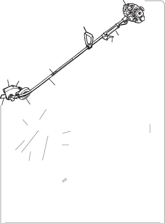
DESCRIPTION
The ECHO product you purchased has been factory pre-assembled for your convenience. Due to packaging restrictions, shield installation and positioning of the front handle are necessary.
After opening the carton, check for damage. Immediately notify your retailer or ECHO Dealer of damaged or missing parts. Use the contents list to check for missing parts.
CONTENTS
__1, Edger Assembly __1, Power Head
__1, Drive Shaft Assembly __1, Plastic Bag (Co-Pack) __1, Operators Manual __1, Safety Manual
__1, Warranty Registration Card
__1, ECHO Emissions and Warranty Statement __1,50:11Gal.ECHOOilMix
__1, Front Handle __2,bolt5x40mm __2, nut 5
__1, split pin
__1, Scrench (Combination Spark Plug Socket/Screwdriver __1, Locking Tool
__1, 10 mm Spanner Wrench __Safety Glasses
13
12
14
15
19
18
17 16
PE-2000 3
5
4
20 |
21 |
|
1
2
11
10
9
8
6 |
7 |

8
CONTENTS |
20 |
21 |
|||
__ |
1, Edger Assembly |
|
|
|
|
__ 1, Power Head |
|
|
|
|
|
__ |
1, Drive Shaft Assembly |
|
|
|
|
__ |
1, Plastic Bag (Co-Pack) |
|
|
|
|
__ |
1, Operators Manual |
|
|
|
|
__ |
1, Safety Manual |
|
|
|
|
__ |
1, Warranty Registration Card |
|
|
|
|
__ 1, ECHO Emissions and Warranty Statement |
|
|
|
|
|
__ 1,50:11Gal.ECHOOilMix |
|
|
|
|
|
__ |
1, Front Handle |
|
|
|
|
__ 4,5X35mmscrews |
|
|
|
|
|
__ 4, 5 mm nuts |
|
|
|
|
|
__ |
1, Scrench (Combination Spark Plug Socket/Screwdriver |
|
|
|
|
__ |
1, split pin |
|
|
|
|
__ 1, 3 mm Hexagon Wrench |
|
|
|
|
|
__ |
1, Locking Tool |
|
|
|
|
__ 1, 10 mm Spanner Wrench |
|
|
|
|
|
__ |
Safety Glasses |
|
|
|
|
13
12 |
1 |
|
|
|
PE-2400 |
|
PE-3100 |
19 |
|
14 |
11 |
|
|
|
2 |
|
18 |
15 |
10 |
|
|
||
|
|
|
9 |
17
16
3
5 4
8
6 |
7 |

POWER EDGER |
9 |
|
OPERATOR'S MANUAL |
||
|
|
|
1.TOP GUARD - Protects arm from the hot engine.
2.FRONT HANDLE - The front handle can be repositioned for comfortable operation by loosening the screws and moving the handle.
3.SHAFTDECAL(Seepage3)
4.GUARDDECAL(Seepage3)
5.DEBRIS SHIELD/FLAP - Mounted over the cutting attachment. Helps protect operator by deflecting debris produced during the edging operation.
6.BLADE - Rotates to provide cutting action.
7.WHEEL - Adjustable up/down, sets depth of blade.
8.DRIVE SHAFT ASSEMBLY - Contains a specially designed liner and the flexible drive shaft.
9.THROTTLE TRIGGER - Spring loaded to return to idle when released. When accelerating, press trigger gradually for best operating technique.
10.GRIP - Rear (right hand) handle.
11.STOPSWITCH-
PE-2000 - "Toggle Switch" mounted on the engine. Move switch UP to RUN, DOWN to STOP.
PE-2400/3100 - "Slide Switch" mounted on top of the throttle Trigger Housing. Move switch FORWARD to RUN, BACK to STOP.
12.CHOKE - The choke control is located on the top of the air filter case (PE-2400, 3100), or on the side of the air filter case(PE-2000).
PE-2000 - Move lever to "COLD START" to close choke for cold starting. Move lever to "RUN" position to open choke.
PE-2400/3100 - Pull choke knob up to close choke for cold starting. Push knob down to "RUN" position to open choke.
13.SPARK PLUG - Provides spark to ignite fuel mixture.
14.MUFFLER/SPARK ARRESTOR -The spark arrestor muffler controls the exhaust noise and prevents hot, glowing particles of carbon from leaving the muffler.
15.FUELTANK- Contains fuel and fuel filter.
16.RECOIL STARTER HANDLE - Pull recoil handle slowly until starter engages, then quickly and firmly. DO NOT let handle snap back or damage to unit will occur.
17.FUEL TANK CAP - Cover and seals fuel tank.
18.PRIMER BULB - Pumping primer bulb before starting engine draws fresh fuel from the fuel tank priming the carburetor for starting. Pump primer bulb until fuel is visible and flows freely in the clear fuel tank return line. Pump bulb an additional 4 or 5 times.
19.AIRCLEANER- Containsreplaceablefeltelement.
20.OPERATORS MANUAL - Read and understand this manual before assembly or operation. Keep manual in a safe location for future reference, i.e., operation, maintenance, storage and specifications.
21.SAFETY MANUAL - Read and understand this manual before assembly or operation, and keep in a safe place for future reference to learn proper, safe operating techniques.
 Loading...