


Multistrada 1000DS

Owner's manual
DUCATIMULTISTRADA
1000DS
E
1

E
2
Hearty welcome among Ducati fans! Please accept our
best compliments for choosing a Ducati motorcycle. We
think you will ride your Ducati motorcycle for long journeys
as well as short daily trips. Ducati Motor Holding S.p.A.
wishes you smooth and enjoyable riding.
We are steadily doing our best to improve our "Technical
Assistance" service. For this reason, we recommend you
to strictly follow the indications given in this manual,
especially for motorcycle running-in. In this way, your
Ducati motorbike will surely give you unforgettable
emotions. Please contact our authorised service centres
to have your motorcycle repaired or if you simply need
advice.
Enjoy your ride!
Note
Ducati Motor Holding S.p.A. declines any liability
whatsoever for any mistakes incurred in drawing up this
manual. The information contained herein is valid at the
time of going to print. Ducati Motor Holding S.p.A.
reserves the right to make any changes required by the
future development of the above-mentioned products.
E
For your safety, as well as to preserve the warranty,
reliability and worth of your motorcycle, use original Ducati
spare parts only.
Warning
This manual forms an integral part of the motorcycle
and - in the event the motorcycle is resold - must always
be handed over to the new owner.
3

TABLE OF CONTENTS
General 6
Warranty 6
Symbols 6
E
Useful information for safe riding 7
Carrying the maximum load allowed 8
Identification data 9
Controls 10
Position of motorcycle controls 10
Instrument panel 11
LCD unit functions 12
LCD - Parameter setting/display 14
Backlighting function 21
Pilot lights brightness function 21
Auto-off headlight function 21
The immobilizer system 21
Keys 22
Code card 23
Procedure to disable immobilizer engine block through
throttle twistgrip 24
Duplicate keys 25
Ignition switch and steering lock 26
4
Left switch 27
Clutch lever 28
Right switch 29
Throttle twistgrip 29
Front brake lever 30
Rear brake pedal 31
Gear change pedal 31
Setting the gear change and rear brake pedals 32
Main components and devices 34
Location 34
Tank filler plug 35
Passenger seat catch and helmet hook 36
Glove compartment lock 37
Side stand 38
Front fork adjusters 39
Rear shock absorber adjusters 41
Rear-view mirrors adjustment 42
Motorcycle trim adjustment 43
Directions for use 44
Running-in recommendations 44
Pre-ride checks 46
Starting the engine 47
Moving off 49
Braking 49
Stopping the motorcycle 50
Parking 50
Refuelling 51
Tool kit and accessories 52

Main maintenance operations 53
Removing the fairing 53
Checking brake and clutch fluid level 58
Checking brake pads for wear 60
Lubricating joints 61
Throttle cable free play adjustment 62
Charging the battery 63
Checking the drive chain tension 64
Chain lubrication 65
Replacing headlamp bulbs 66
Changing the front direction indicators bulbs 70
Changing the rear direction indicators bulbs 71
Changing the number plate and stop light bulbs 72
Beam setting 74
Tubeless tyre pressure 75
Checking engine oil level 77
Cleaning and replacing the spark plugs 78
Cleaning the motorcycle 79
Storing the bike away 79
Important notes 79
Technical data 80
Overall dimensions 80
Weights 80
Engine 82
Timing system 82
Performance data 83
Spark plugs 83
Exhaust system 83
Transmission 84
Brakes 85
Frame 86
Wheels 86
Tyres 86
Suspensions 87
Available in the following colors: 87
Electric system 88
For United States of America version Only 93
Routine maintenance record 102
E
5

GENERAL
Warranty
In your own interest, and in order to guarantee product
reliability, you are strongly advised to refer to a Ducati
E
Dealer or Authorised Workshop for any servicing requiring
particular technical expertise. Our highly skilled staff have
access to the implements required to perform any
servicing job at best, and use Ducati original spare parts
only as the best guarantee for full interchangeability,
smooth running and long life.
All Ducati motorcycles come with a "Warranty Card". The
warranty does not apply to the motorcycles used in
competitions. No motorcycle part may be tampered with,
altered, or replaced with parts other than original Ducati
spare parts during the warranty period, or the warranty will
be automatically invalidated.
6
Symbols
Ducati Motor Holding S.p.A. advises you to read this
booklet carefully so as to become familiar with your
motorcycle. In case of any doubts, please call a Ducati
Dealer or Authorised Workshop. The information
contained herein will prove useful on your trips - and
Ducati Motor Holding S.p.A. wishes you smooth,
enjoyable riding - and will help you keep the performance
of your motorcycle unchanged for a long time.
Warning
Failure to comply with these instructions may put you
at risk and lead to severe injury or death.
Important
Possibility of damaging the motorcycle and/or its
components.
Note
Additional information on the job being carried out.
The terms right and left are referred to the motorcycle
viewed with respect to the direction of travel.
Useful information for safe riding
Warning
Read this section before riding your motorcycle.
Accidents are frequently due to inexperience. Always
make sure you have your licence with you when riding;
you need a valid licence to be entitled to ride your
motorcycle.
Do not lend your motorcycle to inexperienced riders or
who do not hold a valid licence.
Both rider and pillion passenger must always wear a
safety helmet.
Wear proper clothing, with no loose items or accessories
that may become tangled in the controls or limit your zone
of vision.
Never start or run the engine indoors. Exhaust gases are
poisonous and may lead to loss of consciousness or even
death within a short time.
Both rider and pillion passenger should keep their feet on
the footpegs when the motorcycle is in motion.
Always hold handlebar firmly with both hands so you will
be ready for sudden changes of direction or in the road
surface. The pillion passenger should always hold on to
the suitable grab handle at the rear seat with both hands.
Ride within the law and observe national and local rules.
Always respect speed limits where these are posted.
However, always adjust your speed to the visibility, road
and traffic conditions you are riding in.
Always signal your intention to turn or pull to the next lane
in good time using the suitable turn indicators.
Be sure you are clearly visible and do not ride within the
blind spot of vehicles ahead.
Be very careful when tackling road junctions, or when
riding in the areas near exits from private grounds, car
parks or on slip roads to access motorways.
Always turn off the engine when refuelling.
Be extremely careful not to spill fuel on the engine or on
the exhaust pipe when refuelling.
Do not smoke when refuelling.
While refuelling, you may inhale noxious fuel vapours.
Should any fuel drops be spilled on your skin or clothing,
immediately wash with soap and water and change your
clothing.
Always remove the key when you leave your motorcycle
unattended.
The engine, exhaust pipes, and mufflers stay hot for a long
time.
Warning
The exhaust system might be hot, even after engine
is switched off; pay particular attention not to touch
exhaust system with any body part and do not park the
vehicle next to inflammable material (wood, leaves etc.).
Park your motorcycle where no one is likely to hit it and
use the side stand.
Never park on uneven or soft ground or your motorcycle
may fall over.
E
7

Carrying the maximum load allowed
Your motorcycle is designed for long-distance riding,
carrying the maximum load allowed in full safety.
Even weight distribution is critical to preserving these
safety features and avoiding trouble when performing
sudden manoeuvres or riding on bumpy roads.
Information about carrying capacity
The total weight of the motorcycle in running order
including rider, pillion passenger, luggage and additional
accessories should not exceed 410 Kg.
E
8
Arrange your luggage or heavy accessories in the lowest
possible position and close to motorcycle centre.
Be sure to secure the luggage to the supports provided on
the motorcycle as firmly as possible. Improperly secured
luggage may affect stability.
Never fix bulky or heavy objects to the handlebar or to the
front mudguard as this would affect stability and cause
danger.
Do not insert any objects you may need to carry into the
gaps of the frame as these may foul moving parts.
Make sure the tyres are inflated to the proper pressure
indicated at page 75 and that they are in good condition.
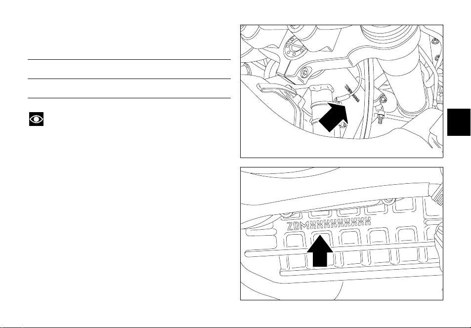
Identification data
All Ducati motorcycles have two identification numbers,
for frame (fig. 1) and engine (fig. 2).
Frame number
Engine number
Note
These numbers identify the motorcycle model and
should always be indicated when ordering spare parts.
E
fig. 1
fig. 2
9
CONTROLS
Warning
This section details the position and function of all the
controls you need to drive your motorcycle. Be sure to
E
read this information carefully before you use the controls.
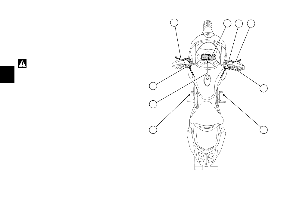
Position of motorcycle controls (fig. 3)
1) Instrument panel.
2) Key-operated ignition switch and steering lock.
3) Left switch.
4) Right switch.
5) Throttle twistgrip.
6) Clutch lever.
7) Front brake lever.
8) Rear brake pedal.
9) Gear change pedal.
10
6
3
1
74
5
2
8 9
fig. 3
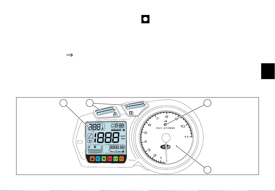
Instrument panel
1) LCD, (see page 12).
2) Control buttons A and B.
Buttons used to display and set instrument panel
parameters.
3) Immobilizer IMMO indicator (amber).
The indicator stays on in case of wrong key code or key
code not recognised; it flashes in case an immobilizer
system warning was reset with the procedure to override
the immobilizer with the throttle twistgrip (see page 24).
Important
The instrument panel allows to making diagnosis on
the electronic injection/ignition system.
These menus are for the trained personnel only; do not
use them for any reason. Should you accidentally enter
this function, turn the key to OFF and contact an
authorised Ducati Service Center for the necessary
inspections.
4) Revolution counter (rpm).
Shows the engine rotation speed/minute.
E
21
km/h
miles
mph
km/L
mpgal
3
4
fig. 4
11

LCD unit functions
Warning
Stop the motorcycle before using the instrument
panel controls. Never operate the instrument panel
controls while riding.
1) Oil temperature warning light.
This function indicates engine oil temperature.
E
Important
Never use the vehicle when the temperature reaches
max. value or the engine might damage.
2) Clock.
3) Tachometer.
This function indicates vehicle speed.
12
4) Auxiliary display.
This function indicates odometer, trip meter, average
speed, instant fuel consumption, average fuel
consumption, fuel used, range and residual fuel quantity,
in this sequence.
5) EOBD light (amber).
When on, this light is used by the control unit to signal the
presence of errors and the consequent engine disabling.
It is also used as a reference light during the immobilizer
overriding procedure with the throttle twistgrip.
If there are no errors, the light should turn on when the
ignition switch is turned ON and should go off after a few
seconds (usually 1.8 - 2 seconds).
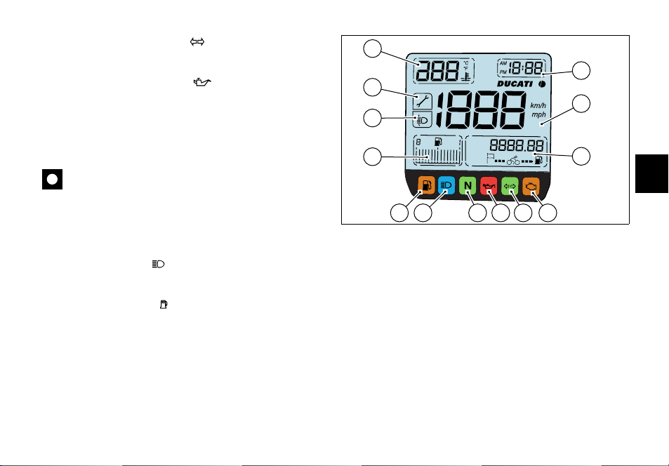
6) Indicators repeater light (green).
Comes on and flashes when a turn indicator is on.
7) Engine oil pressure light (red).
Comes on when engine oil pressure is too low. It briefly
comes on when the ignition is switched to ON and
normally goes out a few seconds after engine starts.
It may shortly come on when the engine is very hot,
however, it should go out as the engine revs up.
Important
If this light (7) stays on, stop the engine or it may
suffer severe damage.
8) Neutral light N (green).
Comes on when in neutral position.
9) High beam light (blue).
Comes on when high beam is on.
10)Fuel warning light (yellow).
Comes on when there are about 6.5 liters fuel left in the
tank.
11) Fuel Display.
This function indicates the quantity of fuel in the fuel tank.
When the last bar stays on (flashing), the low fuel light (10)
comes on.
1
2
13
3
12
km/h
miles
mph
11
km/L
mpgal
9
67810
4
5
fig. 5
12)Beam vertical adjustment indicator.
The pilot light comes on to signal that the user has entered
the beam vertical setting mode.
13)Service warning.
The light comes on to signal that the vehicle has covered
the distance corresponding to a Scheduled Maintenance
interval. The light keeps flashing until the vehicle has
travelled 50 km after hitting the service interval. Then it
stays on permanently. The system shall be reset by the
DUCATI Authorised Service Center that has serviced the
vehicle.
13
E
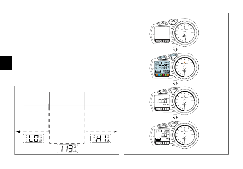
LCD - Parameter setting/display
When turning the key from OFF to ON (Key-ON) the
instrument panel carries out a Check of the whole
instruments: indexes, displays and pilot lights (see fig. 6).
Oil temperature (fig. 7)
This function indicates engine oil temperature.
When temperature is below 40 °C/104 °F a flashing "LO"
message is displayed.
When oil temperature is between 40 °C/104 °F and 170
°C/338 °F temperature measurement is displayed.
E
When oil temperature goes over 170 °C/338 °F a flashing
"HI" message is displayed.
40 ˚C/104 ˚F 170 ˚C/338 ˚F
OFF
km/h
miles
mph
km/L
mpgal
CHECK 1
14
39 ˚C/102 ˚F
171 ˚C/340 ˚F
fig. 7
CHECK 2
km/h
ON
fig. 6
Note
If the sensor measuring the temperature is
disconnected, a string of dashes "- - -" is displayed.
Clock setting function
Hold down button (A, see page 11) for 2 seconds, the
wording AM begins to flash. If button (B) is pressed again,
PM begins to flash; press button (B) to go back to previous
step. Press button (A) to confirm and start setting hours
that shall begin to flash.
Use button (B) to change hour value. If button (B) is
pressed for more than 5 seconds, fast scroll is activated.
Press button (A) to confirm and start setting minutes. Use
button (B) to set minutes. Press button (A) to confirm and
exit clock setting mode and go back to normal operation.
km
miles
km
miles
km/h
mph
km/L
mpgal
ODOMETER
TRIP METER
AVERAGE SPEED
INSTANT FUEL CONSUMPTION
E
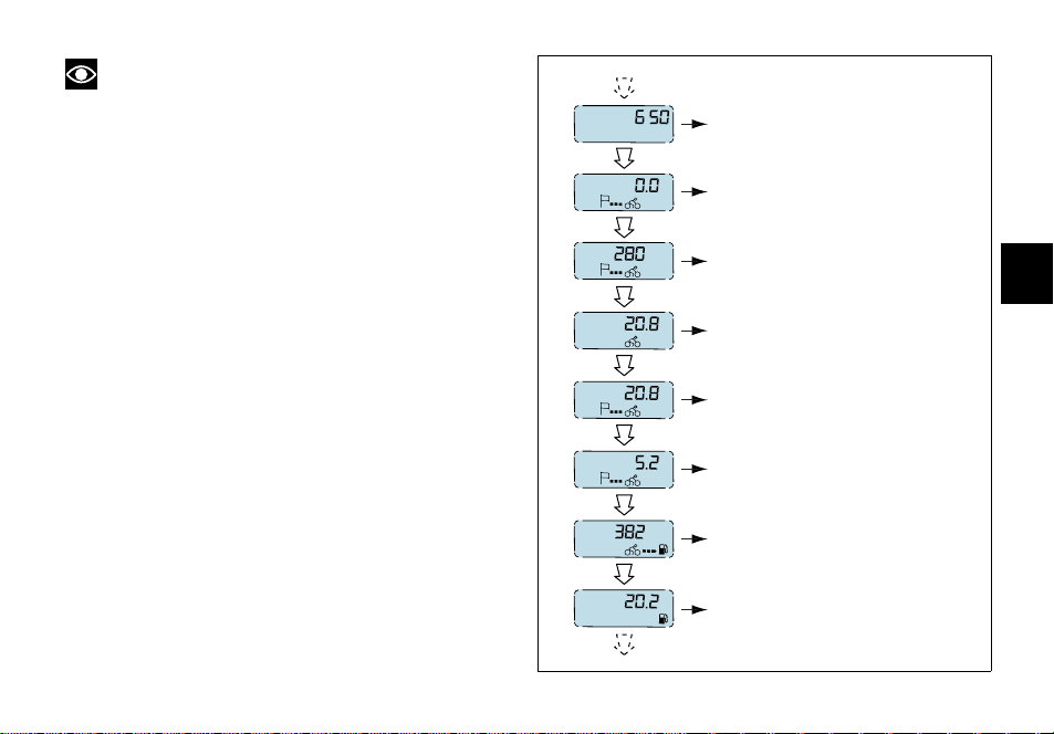
Auxiliary display functions (fig. 8)
Press button (B) with the key on ON to scroll down the
following functions, in sequence:
- Odometer
-TRIP meter
- Average speed
- Instant fuel consumption
- Average consumption
- Fuel used
-Range
-Digital fuel level indication
km/L
mpgal
L
gal
km
miles
L
gal
AVERAGE CONSUMPTION
FUEL USED
RANGE
DIGITAL FUEL LEVEL INDICATION
fig. 8
15
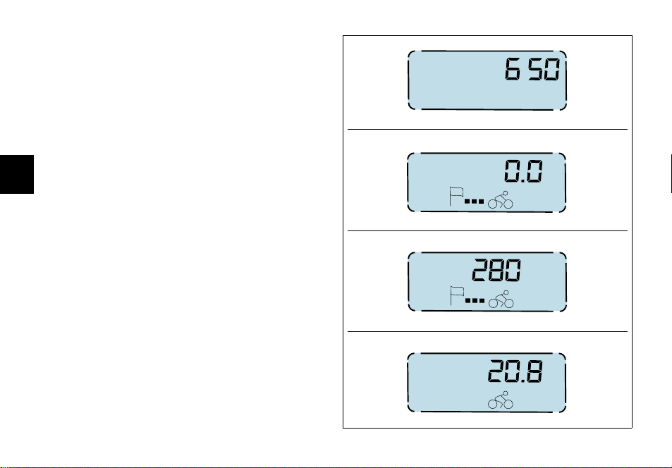
"Odometer" indication (fig. 9)
Indicates total distance covered by the vehicle.
"TRIP meter" indication
This function indicates the distance covered since the
meter was last reset. It is possible to reset this indication
by entering the relevant function and holding down button
(A, see page 11), for at least 2 seconds. When a value of
9999.9 km (or miles) is reached, the display will
E
automatically reset.
"Average speed" indication
This function indicates vehicle average road speed.
Average speed calculation is based on the distance
travelled since the "TRIP meter" was last reset.
"Instant fuel consumption" indication
This function indicates the instant consumption of the
vehicle when in motion. When the vehicle is stopped with
engine running, a string of dashes is displayed "- - . -". With
vehicle stopped and engine off "0.0" is displayed.
16
km
miles
km
miles
km/h
mph
km/L
mpgal
fig. 9
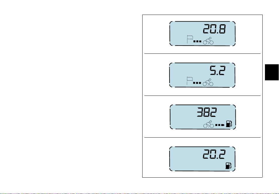
"Average consumption" indication (fig. 10)
This function indicates the vehicle average consumption
when in motion. The calculation is based on the distance
travelled since the "TRIP meter" was last reset. When the
vehicle is stopped, either with the engine off or running,
the last value stored is displayed until indication is
refreshed.
"Fuel used" indication
This function indicates the fuel used by the vehicle to travel
the distance. The calculation is based on the distance
travelled since the "TRIP meter" was last reset. When
indication exceeds 9999.9 liters (2201.9 Imp. gal. - 2641.9
US gal.), the display shows a string of dashes "- - . -".
km/L
mpgal
L
gal
km
miles
L
gal
E
fig. 10
17

"Range" indication
This function indicates how far the vehicle can travel using
the fuel left in the tank. When this display function is not
selected, the display automatically switches to "Range"
indication as soon as the LOW FUEL LIGHT (10, fig. 5)
comes on and the display shows a string of dashes "- - . -"
and the indication for 10 seconds. Range indication is then
turned on automatically every 60 seconds while the low
fuel light stays on.
When the vehicle is stopped, either with the engine off or
running, the last value stored is displayed until indication is
E
refreshed.
Note
The value is refreshed every10 seconds, the
tolerance is 0.5 km.
"Digital fuel level" indication
This function indicates how much fuel is left in the fuel
tank.
When the LOW FUEL LIGHT (10, fig. 5) comes on, the
display shows a string of dashes "- - . -" and the fuel pump
symbol begins to flash.
Note
This vehicle is equipped with a long fuel tank, fuel
level indication might be slightly altered when riding up- or
downhill for a certain period.
18
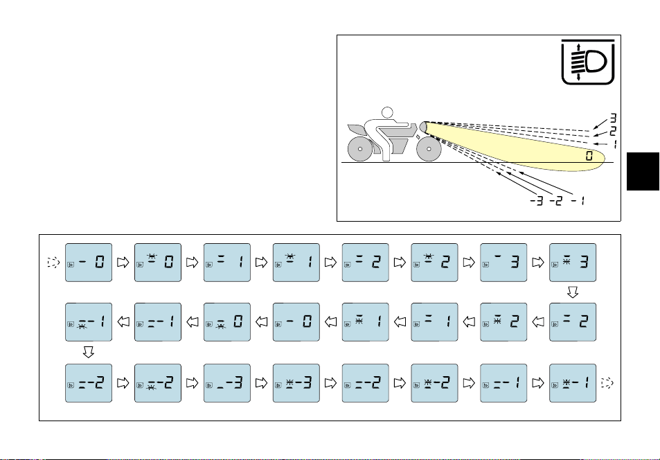
Beam vertical adjustment (fig. 11)
This function allows headlight beam height setting.
To enter this function, hold down button (B, see page 11)
and turn the key to ON; the display shows a value (fig. 11a)
corresponding to beam position and the pilot light on the
display (12, fig. 5) comes on.
Use buttons (A) and (B), respectively, to lower or raise the
beam. Range available is from position "3" (max. beam
height) to position "-3" (min. beam height).
Turn the key to OFF to exit the function. While exiting
setting mode, the selected beam position is stored.
BBBA
AB B B
E
fig. 11
AAAA
fig. 11a
19
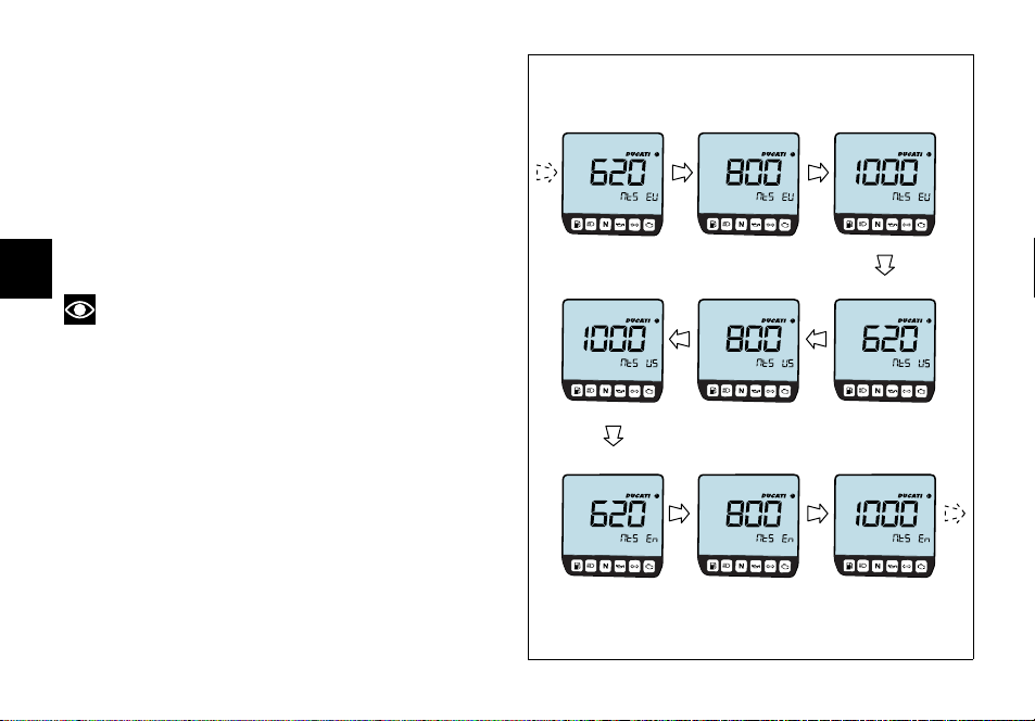
Special selection function: vehicle model and unit of
measurement (fig. 12)
The control unit automatically informs the instrument
panel about the vehicle model and unit of measurement to
be displayed; hold down buttons (A) and (B) and turn
ignition switch from OFF to ON to force the system and
change these parameters. The display shows vehicle
model and version in flashing mode. Press button (B) to
display in sequence all possible settings. To save the
setting chosen hold down button (A) for at least 5
seconds, until OFF is displayed, then turn the key to OFF.
E
Note
When this function is activated, vehicle ignition is
inhibited.
20
fig. 12

Backlighting function
Instrument panel backlighting is active only if the parking
light or the low/high beam is on.
In this case the instrument panel automatically turns on or
off the backlighting, thanks to some sensors measuring
light condition and ambient temperature.
Pilot lights brightness function
This function is active only if the parking light or the low/
high beam is on.
Pilot lights brightness is automatically adjusted by the
instrument panel according to the outer light measured.
Auto-off headlight function
This function allows you to reduce current consumption from
the battery, by automatically managing headlight switching-off.
The device is enabled in two instances:
- If the key is turned from OFF to ON and no attempt is
made to start the engine. After 60 seconds, the
headlight is switched off and will be turned on only
upon the following Key-ON.
- After having used the bike, with headlight on, if the
engine is stopped via the ENGINE KILL switch (2, fig.
19), after 60 seconds from engine stop, the headlight is
turned off and will be turned on upon the following
engine start-up.
Note
While starting the engine, the system switches off
the headlight and turns it back on again after engine has
started, or anyway when the button (3, fig. 19) is released.
The immobilizer system
For improved anti-theft protection, the motorcycle is
equipped with an IMMOBILIZER, an electronic system
that inhibits engine operation whenever the ignition switch
is turned off.
Accommodated in the handgrip of each ignition key is an
electronic device that modulates an output signal. This
signal is generated by a special antenna incorporated in the
switch when the ignition is turned on and changes every
time. The modulated signal acts as a "password" and tells
the CPU that an "authorised" ignition key is being used to
start up the engine. When the CPU recognises the signal,
it enables engine start-up.
21
E
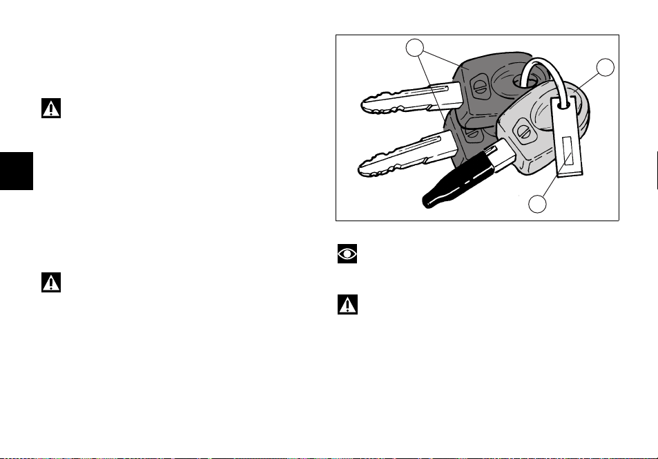
Keys (fig. 13)
The Owner receives a set of keys comprising:
- 1 RED key (A)
- 2 BLACK keys (B)
Warning
Red key has a rubber cover for preserving it in perfect
conditions and avoiding contact with other keys. Never
remove this protection unless really needed.
The black keys are regular ignition keys and are used to:
E
- start up the engine
- open the fuel tank filler plug
- open the seat lock
- release the pillion seat lock.
The red key performs the same functions as the black
keys, and is also used to wipe off and re-program other
black keys, if needed.
Warning
Any important shock might damage the electronic
components fitted into the key.
22
B
A
1
Note
The three keys have a small plate (1) attached that
reports their identification number.
Warning
Keep the keys in different places. Store the plate (1)
and the red key in a safe place.
It is also recommended to use always the same black key
to start the bike.
fig. 13
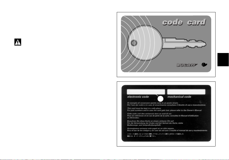
Code card
A CODE CARD (fig. 14) is supplied together with the keys,
it indicates the electronic code (A, fig. 15) to be used in
case the engine is disabled and will not start up after the
key-ON.
Warning
Keep the CODE CARD in a safe place. However, it is
advisable to keep the electronic code printed on the CODE
CARD handy when you ride your motorcycle, in case it is
necessary to remove engine block through the procedure
that uses the throttle twistgrip (see page 24).
In case of faulty immobilizer system, this procedure gives
the chance to disable "engine block" function -signalled by
the orange EOBD warning light (5, fig. 5).
E
fig. 14
A
fig. 15
23

Procedure to disable immobilizer engine block
through throttle twistgrip
1) Turn the key to ON and fully open throttle. Keep it
open. The EOBD warning light turns off after 8
seconds.
2) Release the throttle as soon as the EOBD warning
light turns off.
3) EOBD pilot light will flash. Count a number of flashes
corresponding to the first figure of the code printed on
the CODE CARD, open full throttle and keep the
position for 2 seconds, then release. In this way the
E
input of one figure is acknowledged, EOBD pilot light
comes on and stays on for 4 seconds. Carry out the
same procedure for the following figures of the code.
Failure to do so will cause the EOBD pilot light to flash
20 times, then it will stay on. This means that the
procedure has been aborted. It will be necessary to
turn the key to OFF and restart from point 1.
4) Repeat operations described in point 3 up to the last
figure of the code.
24
5) Release the throttle twistgrip, if the code is correct the
following two conditions may occur:
A) the EOBD warning light shall flash signalling that
engine block has been disabled. The warning light turns
off after 4 seconds or if engine revolutions go over the
limit value of 1000 rpm.
B) the IMMO light (3, fig. 4) flashes until engine rpm
get above 1000 rpm, or until engine is re-started.
6) If the code is NOT correct, the EOBD warning light
and the IMMO light stay on and it is then possible to
repeat the procedure, starting from point 2, as many
times as necessary (infinite).
Note
Should the throttle twistgrip be released before the
set time, the warning light turns on again. It is then
necessary to bring the key to OFF and restart the
procedure from point 1.
Operation
When the ignition key is turned to OFF, the immobilizer
inhibits engine operation.
When the ignition key is turned back to ON to start the
engine (Key-ON), the following happens:
1) if the CPU recognised the code, the IMMO light on the
instrument panel will flash briefly. This means that the
immobilizer system has recognised the key code and
enabled engine ignition. When you press the start
button, the engine will start up.
2) If the IMMO light stays on, it means that the code has
not been recognised. When this is the case, turn the
ignition key back to OFF and then to ON again. If the
engine still does not start, try with another black key.
If the other key does not work out either, contact the
DUCATI Service network.
3) Should the IMMO pilot light still be flashing, it means
that an immobilizer system fault was reset (e.g. with
the overriding procedure through throttle grip).
Important
Use only one key during the procedure. Failure to do
so might prevent the system from recognizing the code of
the key in use.
Duplicate keys
If you need any additional key, contact the DUCATI Service
network with all the keys you have left and your CODE
CARD.
DUCATI Service will program new keys and re-program
your original keys, up to 8 keys in total.
You may be asked to identify yourself as the legitimate
owner of the motorcycle. Be sure you have any
documents you might need to this end ready.
The codes of any keys not submitted will be wiped off
from the memory to make those keys unserviceable in
case they have been lost.
Note
If you sell your motorcycle, do not forget to give all
keys and the CODE CARD to the new owner.
25
E
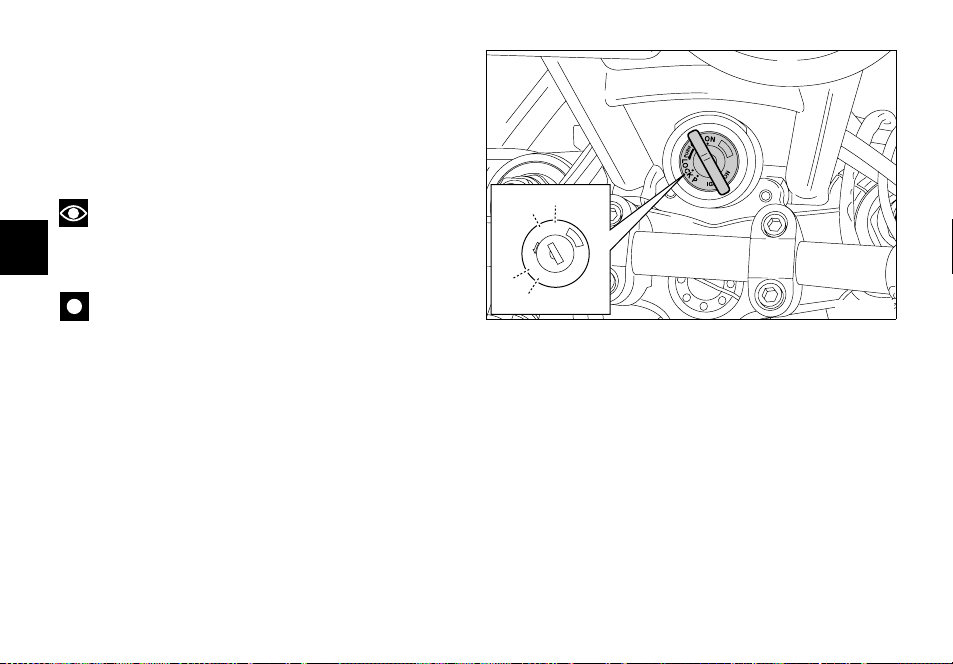
Ignition switch and steering lock (fig. 16)
It is located in front of the steering head and has four
positions:
A) ON: lights and engine on;
B) OFF: lights and engine off;
C) LOCK: steering is locked;
D) P: parking light is ON and steering is locked.
Note
To move the key to the last two positions, press it
down before turning it. Switching to (B), (C) and (D), you
E
will be able to take the key out.
Important
The motorcycle is equipped with an energy-saving
CPU. If the key stays ON for a long period but the ignition
button is not pressed within 15 seconds, the CPU will stop
operating to avoid current absorption. To restore the
system move the key to OFF and then to ON again.
26
A
B
N
O
F
F
O
H
S
U
P
LOCK
P
C
IGNITION
D
fig. 16
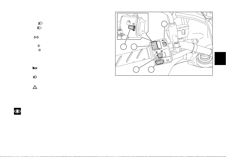
Left switch (fig. 17)
1) Dip switch, light dip switch, two positions:
- position = low beam on;
- position = high beam on.
2) Switch = 3-position turn indicator:
- centre position = OFF;
- position = left turn;
- position = right turn.
To reset turn indicators, push in when switch is back to
central position .
5
4
1
E
3) Button = warning horn.
4) Button = high-beam flasher.
5) Button = Emergency stop flashers
Press this button to turn on all direction indicators at
the same time.
Press it again to turn them off.
Note
When devices (1), (2), (4) and (5) are activated, the
relevant pilot lights on the instrument panel turn on (see
page 13).
32
fig. 17
27
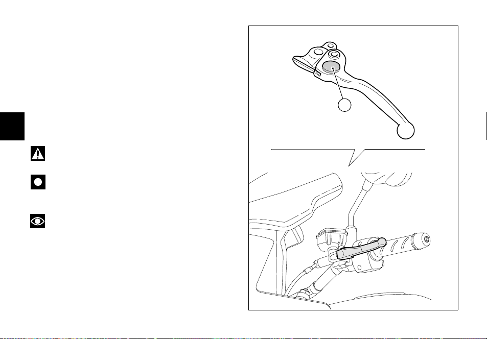
Clutch lever (fig. 18)
Lever (1) disengages the clutch. It features a dial adjuster
(2) for lever distance from the twistgrip on handlebar.
To set lever distance from twistgrip, push lever (1) fully
forward and turn the dial adjuster (2) to one of its four
positions. Remember that position no. 1 gives maximum
distance between lever and twistgrip, whereas lever and
twistgrip are closest when adjuster is set to position no. 4.
When you pull in the lever (1), you will disengage the
engine from the gearbox and therefore from the driving
wheel. Using the clutch properly is essential to smooth
E
riding, especially when moving off.
Warning
Set clutch lever when motorcycle is stopped.
Important
Using the clutch properly will avoid damage to
transmission parts and spare the engine.
Note
It is possible to start the engine with side stand fully
down and the gearbox in neutral. When starting the bike
with a gear engaged, pull the clutch lever (in this case the
side stand must be up).
28
4
3
1
2
2
fig. 18
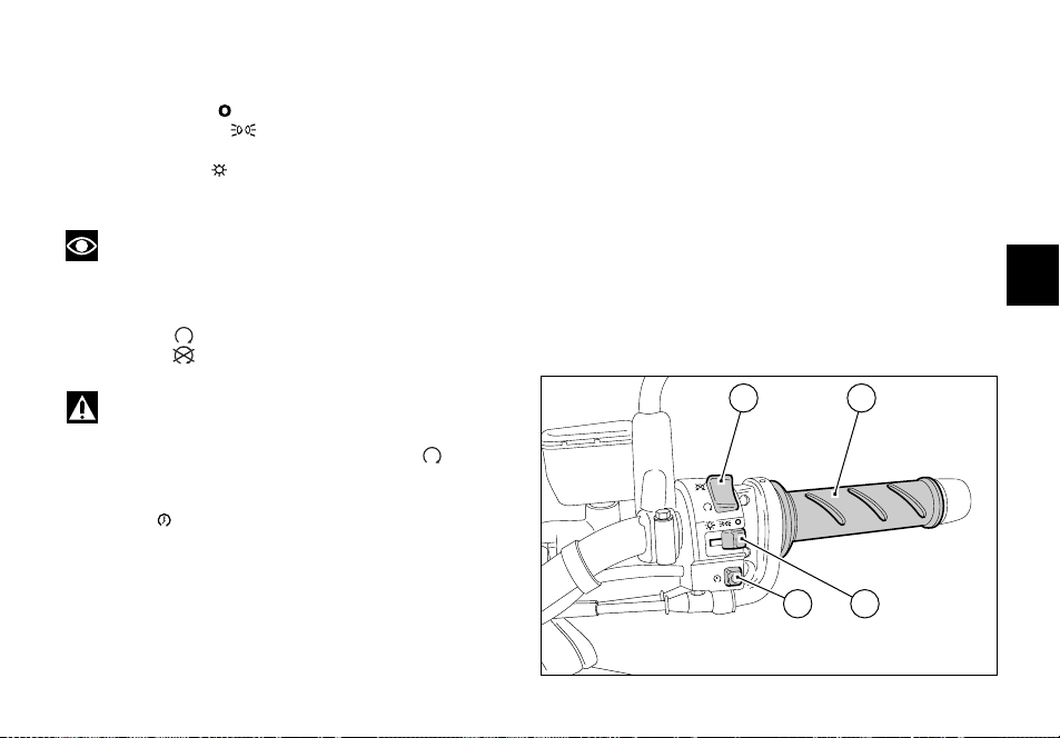
Right switch (fig. 19)
1) Switch, light switch, three positions:
- right position = lights off;
- centre position = front and rear parking lights,
- number plate and instrument panel lights on;
- left position = headlight, front and rear parking
lights, number plate and instrument panel lights on.
Note
This device is not fitted on the Australia and Japan
versions.
2) Switch for engine stop, two positions:
- position (RUN) = run.
- position (OFF) = stop.
Throttle twistgrip (fig. 19)
The twistgrip (4) on the right handlebar opens the throttles.
When released, it will spring back to the initial position
(idling speed).
E
Warning
This switch is mainly intended for use in emergency
cases when you need to stop the engine quickly. After
stopping the engine, return the switch to the position
to enable starting.
3) Button = engine start.
2 4
3
1
fig. 19
29
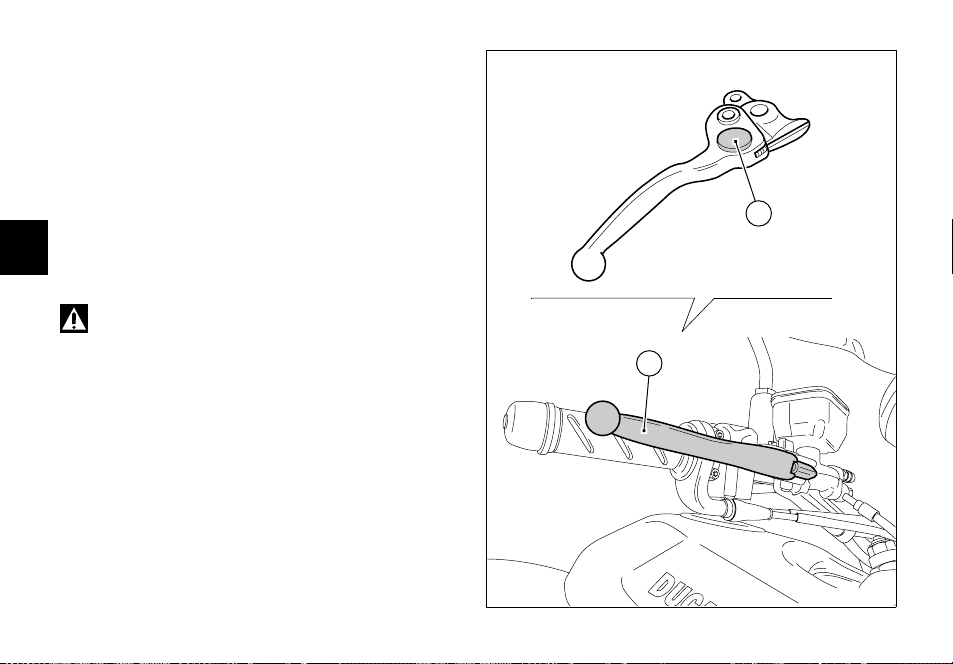
Front brake lever (fig. 20)
Pull in the lever (1) towards the twistgrip to operate the
front brake. The system is hydraulically operated and you
just need to pull the lever gently.
The control lever features a dial adjuster (2) for lever
distance from the twistgrip on handlebar.
To adjust, keep lever (1) completely extended, turn knob
(2) and set it to one of the four available positions.
Consider that:
position no. 1 corresponds to the maximum distance
E
between lever and twistgrip, while position no. 4
corresponds to the minimum distance.
Warning
Front brake lever adjustment is to be carried out
when the bike is stopped.
30
4
3
1
2
2
1
fig. 20
 Loading...