


Owner’s manual
E
DUCATIMONSTERS4R
1

E
2

Hearty welcome among Ducati fans! Please accept out best compliments for choosing a Ducati motorcycle. We think you will ride your Ducati motorcycle for long journeys as well as short daily trips. Ducati Motor Holding S.p.A wishes you smooth and enjoyable riding.
We are steadily doing our best to improve our “Technical Assistance” service. For this reason, we recommend you to strictly follow the indications given in this manual, especially for motorcycle running-in. In this way, your Ducati motorbike will surely give you unforgettable emotions.
For any servicing or suggestions you might need, please contact our authorized service centres.
Enjoy your ride!
Note
Ducati Motor Holding S.p.A. declines any liability whatsoever for any mistakes incurred in drawing up this manual. The information contained herein is valid at the time of going to print. Ducati Motor Holding S.p.A. reserves the right to make any changes required by the future development of the above-mentioned products.
E
For your safety, as well as to preserve the warranty, reliability and worth of your motorcycle, use original Ducati spare parts only.
Warning
This manual forms an integral part of the motorcycle and - if the motorcycle is resold - must always be handed over to the new owner.
3
TABLE OF CONTENTS
E |
General |
6 |
Warranty |
6 |
|
|
Symbols |
6 |
|
Useful information for safe riding 7 |
|
|
Carrying the max load allowed 8 |
|
|
Identification data 9 |
|
Controls 10
Position of motorcycle controls 10 Instrument panel 11
The immobilizer system 14 Keys 14
Code Card 15
Procedure to disable immobilizer engine block through throttle twistgrip 16
Duplicate keys 17
Ignition switch and steering lock 18 Left switch 19
Clutch lever 19 Cold start lever 20 Right switch 20 Throttle twistgrip 21 Front brake lever 21
Rear brake pedal 22 Gear change pedal 22
Setting the gear change pedal 23 Adjusting the rear brake pedal 24
Main components and devices |
25 |
|||
Location 25 |
|
|
|
|
Tank filler plug 26 |
|
|
|
|
Seat catch and helmet fasener |
27 |
|
||
Side stand 28 |
|
|
|
|
Shock absorber adjusters 29 |
|
|
||
Front fork adjusters |
30 |
|
|
|
Changing motorcycle track alignment |
32 |
|||
Directions for use 34 |
|
|
||
Running-in recommendations |
34 |
|
||
Pre-ride checks 36 |
|
|
|
|
Starting the engine |
37 |
|
|
|
Moving off 40 |
|
|
|
|
Braking 40 |
|
|
|
|
Stopping the motorcycle |
41 |
|
|
|
Refueling 41 |
|
|
|
|
Parking 42 |
|
|
|
|
Tool kit and accessories |
43 |
|
|
|
Main maintenance operations |
44 |
|||
Renoving the fairing |
44 |
|
|
|
Lifting the fuel tank |
45 |
|
|
|
Changing air filter 46 |
|
|
|
|
Checking the coolant level 47 |
|
|
||
Checking brake and clutch fluid level |
48 |
|||
4

Checking brake pads for wear 49 Throttle cable adjustment 49 Lubricating cables and joints 50 Charging the battery 51 Checking drive chain tension 52 Chain lubrication 52
Replacing bulbs 53 Headlamp alignment 56 Tyres 58
Checking engine oil level 60
Cleaning and replacing the spark plugs 61 Cleaning the motorcycle 62
Storing the bike away 63 Important notes 63
Technical data 64
Overall dimensions 64
Weights 64
Top-ups 65
Engine 66
Timing system 66
Performance data 67
Spark plugs 67
Brakes 67
Transmission 68
Frame 69
Wheels 69
Tyres 69
Suspensions 69
Electric system 70
Monster S4R versions 73
Monster S4R 73
For United States of America version only 74 Routine maintenance record 85
E
5

GENERAL
Warranty
E In your own interest, and in order to guarantee product reliability, you are strongly advised to refer to our authorized Dealers and workshops for any servicing requiring particular technical expertise. Our highly skilled staff have access to the implements required to perform any servicing job at best, and use Ducati original spare parts only as the best guarantee for full interchangeability, smooth running and long life.
All Ducati motorcycles come with a “Warranty Card”. However, warranty does not apply to the motorcycles used in competitions or competitive trials. No motorcycle part may be tampered with, altered, or replaced with parts other than original Ducati spare parts during the warranty period, or the warranty right will be automatically invalidated.
Symbols
Ducati Motor Holding S.p.A. advises you to read this booklet carefully so as to become familiar with your motorcycle. In case of any doubts, please call a Ducati dealer or authorized workshop. The information contained herein will prove useful on your trips - and Ducati Motor Holding S.p.A. wishes you smooth, enjoyable riding - and will help you keep the performance of your motorcycle unchanged for a long time. The text is supplemented with schematic illustrations for quick reference and better understanding of the subjects concerned.
This manual contains some special remarks:
Warning
Failure to comply with these instructions may put you at risk and lead to severe injury or death.
Important
Possibility of damaging the motorcycle and/or its components.
Note
Additional information concerning the job being carried out.
The terms right and left are referred to the motorcycle direction of travel.
6

Useful information for safe riding
Warning
Read this section before riding your motorcycle.
Accidents are frequently due to inexperience. Always make sure you have your licence with you when riding; you need a valid licence to be entitled to ride your motorcycle.
Do not lend your motorcycle to inexperienced riders or who do not hold a valid licence.
Both rider and pillion passenger must always wear a safety helmet.
Wear proper clothing, with no loose items or accessories that may become tangled in the controls or limit your zone of vision.
Never start or run the engine indoors. Exhaust gases are poisonous and may lead to loss of consciousness or even death within a short time.
Both rider and pillion passenger should keep their feet on the footpegs when the motorcycle is in motion.
Always hold the handlebar firmly with both hands so you will be ready for sudden changes of direction or in the road surface. The pillion passenger should always hold on to the suitable handles under the seat with both hands.
Ride within the law and observe national and local rules. Always respect speed limits where these are posted. However, always adjust your speed to the visibility, road and traffic conditions you are riding in.
Always signal your intention to turn or pull to the next
lane in good time using the suitable turn indicators.
Be sure you are clearly visible and do not ride within the blind spot of vehicles ahead.
Be very careful when tackling road junctions, or when riding in the areas near exits from private grounds, car parks or on slip roads to access motorways.
Always turn off the engine when refueling.
Be extremely careful not to spill fuel on the engine or on the exhaust pipe when refueling.
Do not smoke when refueling. E While refueling, you may inhale noxious fuel vapours.
Should any fuel drops be spilled on your skin or clothing, immediately wash with soap and water and change your clothing.
Always remove the key when you leave your motorcycle unattended.
The engine, exhaust pipes, and mufflers stay hot for a long time.
Warning
The exhaust system might be hot, even after engine is switched off; pay particular attention not to touch exhaust system with any body part and do not park the vehicle next to inflammable material (wood, leaves etc.).
Park your motorcycle where no one is likely to hit it and use the side stand.
Never park on uneven or soft ground or your motorcycle may fall over.
7

Carrying the maximum load allowed
Your motorcycle is designed for long-distance riding, carrying the maximum load allowed in full safety. Even weight distribution is critical to preserving these safety features and avoiding trouble when performing sudden manoeuvres or riding on bumpy roads.
Information about carrying capacity
The total weight of the motorcycle in running order
E including rider, pillion passenger, luggage and additional accessories should not exceed 390 Kg.
Try to arrange your luggage or heavy accessories in the lowest possible position and close to motorcycle centre. Be sure to secure the luggage to the supports provided on the motorcycle as firmly as possible. Improperly secured luggage may affect stability.
Never fix bulky or heavy objects to the handlebar or to the front mud guard as this would affect stability and cause danger.
Do not insert any objects you may need to carry into the gaps of the frame as these may foul moving parts. Make sure the tyres are inflated to the proper pressure (see page 58) and that they are in good condition.
8

Identification data
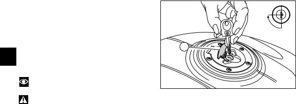
All Ducati motorcycles have two identification numbers, for frame (fig. 1) and engine (fig. 2).
Frame number
Engine number
Note
These numbers identify the motorcycle model and should always be indicated when ordering spare parts.
E |
fig. 1 |
fig. 2 |
9 |
CONTROLS
4 |
1 |
|
8 |
E |
Warning |
3 |
|
This section details the position and function of all |
|||
|
|||
|
the controls you need to drive your motorcycle. Be sure |
|
|
|
to read this information carefully before you use the |
7 |
|
|
controls. |
|
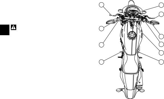
Position of motorcycle controls (fig. 3)
1)Instrument panel.
2)Key-operated ignition switch and steering lock.
3)Left switch.
4)Clutch lever.
5)Cold start lever.
6)Right switch.
7)Throttle twistgrip.
8)Front brake lever.
9)Gear change pedal.
10)Rear brake pedal.
5 |
6 |
2 |
9 |
10 |
fig. 3
10
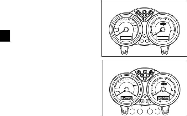
Instrument panel (fig. 4)
1)High beam light  (blue). Comes on when high beam is on.
2)Turn indicator light  (green).
Comes on and flashes when a turn indicator is on. 3) Fuel warning light  (yellow).
Comes on when there are about 3.5 liters fuel left in the tank.
4)Neutral light N (green).
Comes on when in neutral position.
5)Engine oil pressure light  (red).
Comes on when engine oil pressure is too low. It briefly comes on when the ignition is switched to ON and normally goes out a few seconds after engine starts.
It may shortly come on when the engine is hot, however, it should go out as the engine revs up.
Important
If this light stays on, stop the engine or it may suffer severe damage.
6) Orange light
Comes on and flashes when the motorcycle is parked (Immobilizer on), it is also used for immobilizer diagnosis.
Note
When the Immobilizer is on, this light flashes for 24 hours and then goes out. The Immobilizer is still operating.
7) EOBD light  (orange)
When on, engine operation is inhibited. It goes out after a few seconds (usually 1.8 - 2 sec.).
8) Speedometer (km/h). Gives road speed.
a) LCD (1):
- Odometer (km).
Gives total distance covered. - Trip meter (km).
Gives distance covered since last resetting. E
9) Revolution counter (rpm).
Shows the engine rotation speed/minute. b) LCD (2):
-Clock
-Oil temperature
8 |
1 |
4 |
2 |
5 |
3 |
9 |
|
|
|
7 |
|
|
|
|
|
|
6 |
|
|
|
|
|
a |
|
|
b |
fig. 4 |
|
|
|
|
|
|
|
|
|
|
|
|
|
11 |
LCD unit functions
When the ignition key is turned to ON, the instrument panel carries out a Check of all instruments (pointers, display, lights) (see fig. 5 and 6).
LCD (1)
Turn the key to ON and press (B) (fig. 6) to display trip meter and odometer alternatively.
E Resetting the trip meter
Keep (B) pressed (fig. 6) for more than 2 seconds. When the TRIP function is enabled (trip meter), display (LCD 1) will reset.
LCD (2)
Turn the key to ON and press (A) (fig. 6) to display clock and water temperature.
Setting the clock
Press (A) for at least 2 seconds. Press (B) to set AM/PM.
Press (A) to set hours; press (B) repeatedly to set correct hour.
Press (A) to set minutes.
Press (B) to increase the value. Keep the button pressed for more than 5 seconds to proceed faster.
Press (A) to quit this function.
OFF
fig. 5
CHECK
1 |
A |
B |
2 |
fig. 6 |
|
|
|
|
12
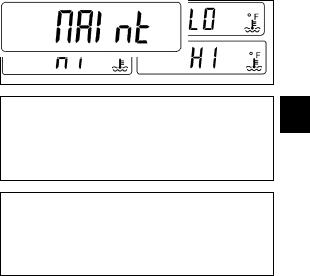
Water temperature
When the water temperature goes below 40 °C (104 °F), "LO" will be displayed. "HI" will be displayed when the temperature exceeds 120 °C (248 °F).
Fuel light
"FUEL" will be displayed when the fuel warning light comes on.
Maintenance indicator
After the first 1,000 Km (621 miles) and then every 10,000 Km (6210 miles), "MAInt" will be displayed for 5 seconds when turning the key to ON. It reminds you of the routine maintenance servicing to be done.
Instrument panel backlighting
Turn the key to ON and press (B) (fig. 6) within 5 seconds to change instrument panel lighting power.
E
13
The immobilizer system
For improved anti-theft protection, the motorcycle is equipped with an IMMOBILIZER, an electronic system that inhibits engine operation whenever the ignition switch is turned off.
Accommodated in the handgrip of each ignition key is an electronic device that modulates an output signal. This signal is generated by a special antenna incorporated in the switch when the ignition is turned on and changes
E every time. The modulated signal acts as a “password” and tells the CPU that an "authorised" ignition key is being used to start up the engine. When the CPU recognises the signal, it enables engine start-up.
The key A performs the same functions as the keys B, and is also used to wipe off and re-program other black keys, if needed.
Note
The three keys have a small plate (1) attached that reports their identification number.
Warning
Keep the keys in different places. Store the plate (1) and the key A in a safe place.
It is also recommended to use always the same black key to start the bike.
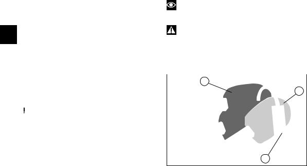
Keys (fig. 7) |
B |
|||
The Owner receives a set of keys comprising: |
||||
- 1 RED key A |
A |
|||
- 2 BLACK keys B |
||||
|
||||
|
|
Warning |
|
|
|
|
|
||
|
|
Red key A has a rubber cover for preserving it in |
|
|
|
|
|
||
|
|
|
||
perfect conditions and avoiding contact with other keys. |
|
|||
Never remove this protection unless really needed. |
|
|||
The keys B are regular ignition keys and are used to:
-start up the engine
-open the lock of the fuel tank filler plug
- open the seat lock. |
1 |
|
|
fig. 7 |
|
|
|
14
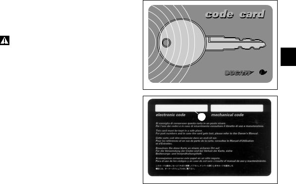
Code card
The keys come with a CODE CARD (fig. 8) that reports:
A) (fig. 9) the electronic code to be used in case of engine block, i.e. bike did not start after key-ON.
Warning
Keep the CODE CARD in a safe place. However, it is advisable to keep the electronic code printed on the CODE CARD handy when you ride your motorcycle, in case it is necessary to override engine block through the procedure that uses the throttle twistgrip.
In case of faulty immobilizer system, the following procedure gives the chance to disable "engine block" function -signalled by the orange EOBD warning light that comes on immediately (7, fig. 4).
But this operation can be carried out only if the electronic code indicated on the code card is known.
|
E |
|
fig. 8 |
A |
B |
fig. 9
15

Procedure to disable immobilizer engine block through throttle twistgrip
1)Turn the key to ON and fully open throttle. Keep it open. The EOBD warning light turns off after 8 seconds.
2)Release the throttle as soon as the EOBD warning light turns off.
3)EOBD pilot light will flash. Count a number of flashes corresponding to the first figure of the code, fully open throttle and keep the position for 2 seconds, then
E release. In this way the input of one figure is acknowledged, EOBD pilot light comes on and stays on for 4 seconds. Carry out the same procedure for the following figures of the code. Failure to do so will cause the EOBD pilot light to flash 20 times, then it will stay on. This means that the procedure has been aborted. It will be necessary to turn the key to OFF and restart from point (1).
4)Repeat operations described in point (3) up to the last figure of the code.
5)Release the throttle twistgrip, if the code is correct, the EOBD warning light shall flash signalling that engine block has been disabled. The warning light turns off after 4 seconds.
If the code is NOT correct, the EOBD warning light stays on and it is then possible to turn the key to OFF and repeat the procedure, starting from point (1), as many times as necessary (infinite).
Note
Should the throttle twistgrip be released before the set time, the warning light turns on again. It is then necessary to bring the key to OFF and restart the procedure from point (1).
16

Operation
When the ignition key is turned to OFF, the immobilizer inhibits engine operation.
When the ignition key is turned back to ON to start the engine, the following happens:
1)if the CPU recognised the code, the CODE light on the instrument panel will flash briefly. This means that the immobilizer system has recognised the key code and enabled engine ignition. When you press the START button, the engine will start up.
2)If the CODE light stays on, it means that the code has not been recognised. When this is the case, turn the ignition key back to OFF and then to ON again. If the engine still does not start, try with another black key.
If the other key does not work out either, contact the DUCATI Service network.
3)Should the CODE pilot light still be flashing, it means that an immobilizer system fault was reset (e.g. with the overriding procedure through throttle grip). Turn the key to OFF and back to ON, the immobilizer pilot light should go back to its normal operation (see point 1).
Warning
The keys accommodate electronic components inside. If dropped or hit, they might damage.
Always use the same key during the procedure. Failure to do so might prevent the system from recognizing the code of the key in use.
Duplicate keys
If you need any duplicate keys, contact the DUCATI Service network with all the keys you have left and your CODE CARD.
DUCATI Service will program new keys and re-program your original keys, up to 8 keys in total.
You may be asked to identify yourself as the legitimate owner of the motorcycle. Be sure you have any documents you might need to this end ready.
The codes of any keys not submitted will be wiped off E from the memory to make those keys unserviceable in
case they have been lost.
Note
If you sell your motorcycle, do not forget to give all keys and the CODE CARD to the new owner.
17
|
|
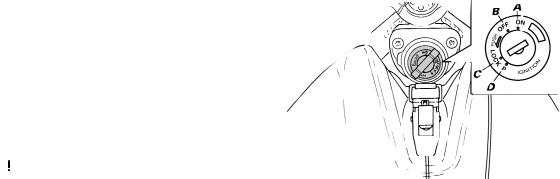
Ignition switch and steering lock (fig. 10) |
|
|
|
||
|
|
It is located in front of the fuel tank and has four |
|
|
|
||
|
|
positions: |
|
|
|
||
|
|
A) ON: lights and engine on; |
|
|
|
||
|
|
B) OFF: lights and engine off; |
|
|
|
||
|
|
C) LOCK: steering locked; |
|
|
|
||
|
|
D) P: parking light and steering lock. |
|
|
|
||
|
|
|
|
Note |
|
|
|
E |
|
|
|
|
|
||
|
|
|
To move the key to the last two positions, press it |
|
|
|
|
|
|
|
|
|
|
||
|
|
down before turning it. Switching to (B), (C) and (D), you |
|
|
|
||
|
|
will be able to take the key out. |
|
|
|
||
|
|
|
|
Warning |
|
|
|
|
|
|
|
|
|
|
|
|
|
|
|
This vehicle is equipped with an energy-saving |
|
fig. 10 |
|
|
|
|
|
|
|
||
|
|
|
|
|
|
||
|
|
CPU. If the key stays ON for a long period but the |
|
|
|
||
|
|
|
|
|
|||
|
|
|
|
||||
|
|
ignition button is not pressed within 15 seconds, the |
|
|
|
||
CPU will stop operating to avoid current absorption.
Move the key to OFF and then to ON again.
18
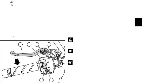
Left switch (fig. 11)
1)Dip switch, light dip switch, two positions: position  = low beam on;
position  = high beam on.
2)Switch  = 3-position turn indicator: centre position = OFF;
position  = left turn;
position  = right turn.
To reset turn indicators, turn switch to central position and push in.
3)Button  = warning horn.
4)Button  = passing.
5 |
4 |
6 |
1 |
|
|
|
3 |
2 |
fig. 11 |
Clutch lever (fig. 11)
Lever (5) disengages the clutch. It features a ring nut adjuster (6) for lever distance from the twistgrip on
handlebar. |
|
To set lever distance from |
twistgrip, push lever (5) fully |
forward and turn the ring nut adjuster (6) to one of its |
|
four positions. Remember that position no. 1 gives |
|
maximum distance between lever and twistgrip, whereas |
|
lever and twistgrip are closest when adjuster is set to |
|
position no. 4. |
E |
When you pull in the lever (5), you will disengage the engine from the gearbox and therefore from the driving wheel. Using the clutch properly is essential to smooth riding, especially when moving off.
Warning
Set clutch and brake lever when motorcycle is stopped.
Important
Using the clutch properly will avoid damage to transmission parts and spare the engine.
Note
It is possible to start the engine with side stand down and the gearbox in neutral. When starting the bike with a gear engaged, pull the clutch lever (in this case the side stand must be up).
19
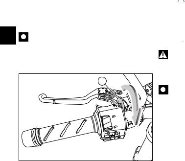
Cold start lever (fig. 12)
Use this device (7) to start the engine from cold. It will increase the engine idling speed after starting.
Lever positions:
A)= closed
B)= fully open.
The lever can be opened and closed gradually to adjust speed until engine is fully warm (see page 37).
E Important
Never use the cold start lever when the engine is warm or leave it open when riding.
7 |
A |
|
B |
|
fig. 12 |
20 |
|
Right switch (fig. 13)
1)Switch, light switch, 3 positions:
Right  = light off;
Centre 
 = front and rear parking light, number plate light and panel lights on;
Left 

 = headlamp, front and rear parking light, number plate light and panel lights on.
2)Switch for ENGINE STOP, two positions:
position  (RUN) = run. position
  (OFF) = stop.
Warning
This switch is mainly intended for use in emergency cases when you need to stop the engine quickly. After stopping the engine, return the switch to the 
position to enable starting.
Important
Riding with the lights on, stopping the engine using switch (2) and leaving the ignition key in the ON position, may run the battery flat as the lights will remain on.
3) Button  = engine start.
Throttle twistgrip (fig. 13)
The twistgrip (4) on the right handlebar opens throttles. When released, it will spring back to the initial position (idling speed).
Front brake lever (fig. 14)
Pull in the lever (5) towards the twistgrip to operate the front brake. The system is hydraulically operated and you just need to pull the lever gently.
The control lever is provided with a ring nut adjuster (6) for lever distance adjustment from twistgrip on handlebar (see clutch lever adjustment page 19).
Warning
Please read the instructions on page 40 before using these controls.
2 |
1 |
3 |
4 |
E
fig. 13
6 |
5 |
fig. 14
21
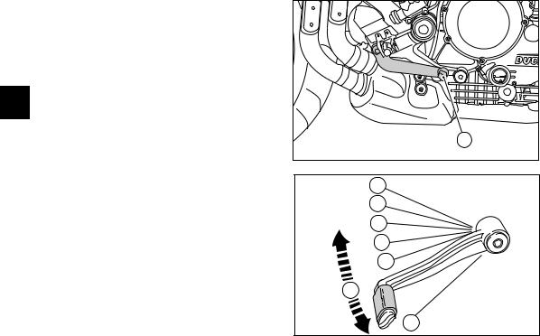
Rear brake pedal (fig. 15)
Push down on the pedal (1) to apply the rear brake. The system is hydraulically operated.
E
Gear change pedal (fig. 16)
The gear change pedal is at rest when in the central position N, is moved up and down to change gears and then returns to the central position.
Down = push down on the pedal to engage 1st gear and to shift down. The N light will go out.
Up = lift the pedal to engage the 2nd gear and then the 3rd, 4th, 5th and 6th gear.
Each time you move the pedal you will engage the next gear.
22
|
1 |
|
fig. 15 |
6 |
|
5 |
|
4 |
|
3 |
|
2 |
|
N |
|
1 |
fig. 16 |
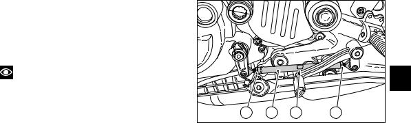
Setting the gear change pedal (fig. 17)
The gear change lever can be adjusted to suit the preferred riding position of each rider.
To set the gear change pedal,
Use socket (2) to lock linkage (1) and loosen the check nuts (3) and (4).
Note
Nut (3) has a left-hand thread.
Rotate linkage (1) until setting pedal in the desired position.
Tighten both check nuts onto linkage.
|
|
|
|
E |
3 |
1 |
2 |
4 |
fig. 17 |
|
|
|
|
23
|
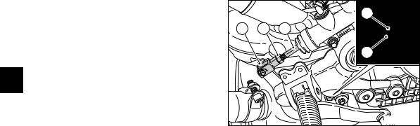
Adjusting the rear brake pedal position (fig. 18) |
|
|
|
|
In order to suit any rider preferred riding position, it is |
|
|
6 |
|
possible to change the rear brake lever position with |
|
|
|
|
respect to the footpegs. |
9 |
7 |
8 |
|
To set the rear brake pedal, |
|
|
|
|
loosen check nut (5). |
|
|
5 |
|
Turn pedal travel adjusting screw (6) until pedal is in the |
|
|
|
|
desired position. |
|
|
|
E |
Tighten check nut (5). |
|
|
|
Work pedal by hand to make sure it has 1.5 - 2 mm free |
|
|
|
|
|
play before brake begins to bite. |
|
|
|
|
If not so, set the length of cylinder linkage as follows. |
|
|
|
|
Loosen the check nut (7) on cylinder linkage. |
|
|
|
|
Tighten linkage (8) into fork (9) to increase play, or |
|
|
fig. 18 |
|
unscrew linkage to reduce it. |
|
|
|
|
Tighten check nut (7) and check pedal free play again. |
|
|
|
24
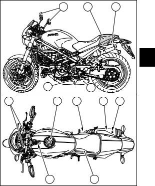
MAIN COMPONENTS AND DEVICES
Location (fig. 19)
1)Tank filler plug.
2)Seat catch.
3)Hook for helmet fastening cable.
4)Passenger grab handle.
5)Side stand.
6)Rear view mirrors.
7)Rear shock absorber adjusters.
8)Front fork adjusters.
9)Fuel tank lifting rod.
10)Seat cover.
11)Fuel tank clip.
12)Catalyser.
|
6 |
|
10 |
4 |
|
|
|
|
E |
|
5 |
|
12 |
|
8 |
1 |
7 |
2 |
3 |
|
11 |
|
9 |
fig. 19 |
|
|
|
|
25 |
Tank filler plug (fig. 20) |
|
|
Opening |
1/4 |
|
Lift the protection lid (1) and fit the ignition key into the |
|
|
lock. Turn the key clockwise 1/4 turn to unlock. |
OPEN |
|
Lift the plug. |
0 |
|
Closing |
1 |
|
Refit the plug with the key in it and push it down into its |
||
|
||
E seat. Turn the key anticlockwise to its initial position and |
|
|
take it out. |
|
|
Close the lock protection lid (1). |
|
|
Note |
fig. 20 |
|
The plug can only be closed with the key in. |
Warning
Always make sure you have properly refitted (see page 41) and closed the plug after each refueling.
26
 Loading...