


Owner’s manual
E
DUCATIMH900evoluzione 
1

E
2

Hearty welcome among Ducati fans! Please accept ou t best compliments for choosing a Ducati motorcycle. We think you will ride your Ducati motorcycle for long journeys as well as short daily trips. Ducati Motor Holding S.p.A. wishes you smooth and enjoyable riding.
We are steadily doing our best to improve our “Technical Assistance” service. For this reason, we recommend that you strictly follow the indications given in this manual, especially for motorcycle running-in. In this way, your Ducati motorcycle will surely give you unforgettable emotions. Please contact our authorised service centres to have your motorcycle repaired or if you simply need advice.
Enjoy your ride!
Ducati Motor Holding S.p.A. declines any liability whatsoever for any mistakes incurred in drawing up this manual. The information contained herein is valid at the time of going to print. Ducati Motor Holding S.p.A. reserves the right to make any changes required by the future development of the above-mentioned products.
E
For your safety, as well as to preserve the warranty, reliability and worth of your Ducati motorcycle, use original Ducati spare parts only.
Warning
This manual forms an integral part of the motorcycle and - if the motorcycle is resold - must always be handed over to the new owner.
3
TABLE OF CONTENTS
E |
General |
6 |
Warranty |
6 |
|
|
Symbols |
6 |
|
Useful information for safe riding 7 |
|
|
Carrying the max load allowed 8 |
|
|
Accessories 8 |
|
|
Identification data 9 |
|
Controls |
10 |
|
|
Position of motorcycle controls |
10 |
||
Instrument panel |
11 |
|
|
Digital LCD functions 12 |
|
||
Keys 13 |
|
|
|
Ignition switch and steering lock |
13 |
||
Left switch |
14 |
|
|
Clutch lever |
15 |
|
|
Fast-idle lever 15 |
|
|
|
Right switch |
16 |
|
|
Throttle twistgrip |
16 |
|
|
Front brake lever |
16 |
|
|
Rear brake pedal |
17 |
|
|
Gear change pedal |
17 |
|
|
Setting the gear change pedal 18
Setting the rear brake pedal 18
Main components and devices 19
Location 19
Tank filler plug 20 Side stand 20
Shock absorber adjusters 21 Steering damper 22
Directions for use 23
Running-in recommendations 23 Pre-ride checks 24
Starting the engine 25 Moving off 27 Braking 27
Stopping the motorcycle 28 Refuelling 28
Parking 29
Tool kit and accessories 30
Main maintenance operations |
31 |
||
Removing the seat 31 |
|
|
|
Removing the front fairing 32 |
|
||
Removing the body 32 |
|
|
|
Removing the fuel tank |
33 |
|
|
Refitting the fuel tank |
34 |
|
|
Changing the air filter |
36 |
|
|
Checking brake and clutch fluid level |
37 |
||
Checking brake pads for wear |
38 |
|
|
Lubricating cables and joints |
38 |
|
|
Throttle cable adjustment 39 |
|
|
|
4

Charging the batteries 40
Checking the drive chain tension 41 Chain lubrication 41
Replacing bulbs 42 Beam setting 45 Tyres 46
Checking engine oil level 48
Cleaning and replacing the spark plugs 49 Cleaning the motorcycle 50
Storing the bike away 50 Important notes 50
Technical data 51
Overall dimensions 51
Weights 51
Top-ups 52
Engine 53
Timing system 53
Performance data 54
Spark plugs 54
Brakes 54
Transmission 55
Frame 56
Wheels 56
Tyres 57
Suspensions 57
Electric system 58
For United States of America version only 62 Routine maintenance record 71
E
5

GENERAL
Warranty
E In your own interest, and in order to guarantee product reliability, you are strongly advised to refer to our Authorised Dealers and Workshops for any servicing requiring particular technical expertise. Our highly skilled staff have access to the implements required to perform any servicing job at best, and use Ducati original spare parts only as the best guarantee for full interchangeability, smooth running and long life.
All Ducati motorcycles come with a Warranty Booklet. However, warranty does not apply to the motorcycles used in competitions or competitive trials. No motorcycle part may be tampered with, altered, or replaced with parts other than original Ducati spare parts during the warranty period, or the warranty right will be automatically invalidated.
Symbols
Ducati Motor Holding S.p.A. advises you to read this booklet carefully so as to become familiar with your motorcycle. In case of any doubts, please contact a Ducati Dealer or Authorised Workshop. The information contained herein will prove useful on your trips - and Ducati Motor Holding S.p.A. wishes you smooth, enjoyable riding - and will help you keep the performance of your motorcycle unchanged for a long time. This manual contains some special remarks:
Warning
Failure to comply with these instructions may put you at risk and lead to severe injury or death.
Important
Possibility of damaging the motorcycle and/or its components.
Note
Additional information concerning the job being carried out.
The terms right and left are referred to the motorcycle viewed from the riding position.
6

Useful information for safe riding
Warning
Read this section before riding your motorcycle.
Accidents are frequently due to inexperience. Always make sure you have your licence with you when riding; you need a valid licence to be entitled to ride your motorcycle.
Do not lend your motorcycle to inexperienced riders or who do not hold a valid licence.
Always wear a safety helmet.
Wear proper clothing, with no loose items or accessories that may become tangled in the controls or limit your zone of vision.
Never start or run the engine indoors. Exhaust gases are poisonous and may lead to loss of consciousness or even death within a short time.
Keep your feet on the footpegs when the motorcycle is in motion.
Always hold the handlebar firmly with both hands so you will be ready for sudden changes of direction or in the road surface.
Ride within the law and observe national and local rules. Always respect speed limits where these are posted. However, always adjust your speed to the visibility, road and traffic conditions you are riding in.
Always signal your intention to turn or pull to the next lane in good time using the suitable turn indicators.
Be sure you are clearly visible and do not ride within the blind spot of vehicles ahead.
Be very careful when tackling road junctions, or when riding in the areas near exits from private grounds, car parks or on slip roads to access motorways.
Always turn off the engine when refuelling.
Be extremely careful not to spill fuel on the engine or on the exhaust pipe when refuelling.
Do not smoke when refuelling.
While refuelling, you may inhale noxious fuel vapours. Should any fuel drops be spilled on your skin or clothing,
immediately wash with soap and water and change your E clothing.
Always remove the key when you leave your motorcycle unattended.
The engine, exhaust pipes, and mufflers stay hot for a long time.
Park your motorcycle where no one is likely to hit it and use the side stand.
Never park on uneven or soft ground or your motorcycle may fall over.
7

Carrying the maximum load allowed
Your motorcycle is designed for long-distance riding, carrying the maximum load allowed in full safety. Even weight distribution is critical to preserving these safety features and avoiding trouble when performing sudden manoeuvres or riding on bumpy roads.
Information about carrying capacity
The total weight of the motorcycle in running order
E including rider, luggage and additional accessories should not exceed 290 Kg.
Try to arrange your luggage or heavy accessories in the lowest possible position and close to motorcycle centre. Be sure to secure the luggage to the supports provided on the motorcycle as firmly as possible. Improperly secured luggage may affect stability.
Never fix bulky or heavy objects to the handlebars or to the front mud guard as this would affect stability and cause danger.
Do not insert any objects you may need to carry into the gaps of the frame as these may foul moving parts. Make sure the tyres are inflated to the proper pressure (see page 46) and that they are in good condition.
Accessories
The motorcycle is supplied with paddock stand and authenticity certificate.
8
Identification data
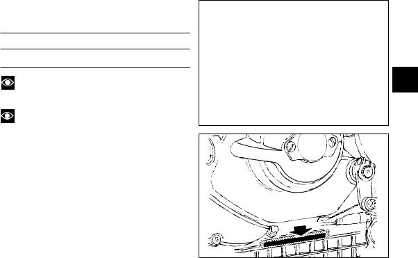
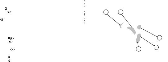
All Ducati motorcycles have two identification numbers, for frame (fig. 1.1) and engine (fig. 1.2).
Frame number
Engine number
Note
These numbers identify the motorcycle model and should always be indicated when ordering spare parts.
Note
To expose engine serial number, remove the oil sump guard on the left side.
E
fig. 1.1
 fig. 1.2 9
|
CONTROLS |
|
|
|
|
1 |
2 |
|
|
4 |
|
E |
Warning |
|
|
This section details the position and function of all |
|
|
|
|
the controls you need to drive your motorcycle. Be sure |
3 |
|
|
to read this information carefully before you use the |
6 |
|
|
|
||
|
controls. |
5 |
|
|
Position of motorcycle controls (fig. 2) |
|
|
|
1) Instrument panel. |
9 |
10 |
|
2) Key-operated ignition switch and steering lock. |
||
|
|
|
3)Left switch.
4)Clutch lever.
5)Fast-idle lever.
6)Right switch.
7)Throttle twistgrip.
8)Front brake lever.
9)Gear change pedal.
10)Rear brake pedal.
8
7
fig. 2
10
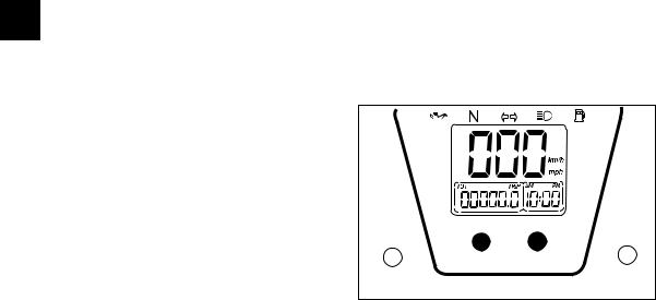
Instrument panel (fig. 3)
1) Multi-purpose digital LCD.
It provides these functions:
a) Speedometer (kph or mph).
Gives road speed based on the input from a sensor located on sprocket cover.
b1) Odometer (km or miles). Gives total distance covered. b2) Trip meter (km or miles).
Gives distance covered since last resetting. c) Clock
2 and 3) Control buttons.
Push these buttons to select the different digital LCD functions.
4) Green light N.
Comes on when gearbox is in neutral. 5) Yellow light  .
.
Comes on when there are about 4 litres of fuel left in the
tank. |
|
6) Green light |
. |
Comes on and flashes when a turn indicator is on. 7) Red light  .
.
Comes on when engine oil pressure is too low. It briefly comes on when the ignition is switched to ON and normally goes out a few seconds after engine starts.
It may shortly come on when the engine is hot, however, it should go out as the engine revs up.
Important
If this light stays on, do not ride your motorcycle or the engine may suffer severe damage.
8) Blue light |
. |
|
|
Comes on when high beam is on. |
|
||
When the parking light is on, the instrument panel lights |
|
||
up. |
|
|
|
9) Revolution counter (rpm). |
|
||
E |
|||
Shows engine revolutions per minute. This is an |
|||
electronic counter operated by a stepper motor. When |
|
||
the parking light is on, the instrument panel lights up.
9
|
|
DUCATI |
4 |
|
|
7 |
|
|
1 |
|
6 |
|
|
|
a |
|
5 |
|
|
|
b1 |
8 |
|
b |
2 |
c |
|
|
|
2 |
3 |
|
fig. 3
11
Digital LCD functions
Check
When the ignition key is switched ON, the rev counter is set to zero, all figures on the LCD come on for 2 seconds, all warning lights come on and total distance covered is displayed.
Odometer/trip meter
Press button 1 with the key in the ON position to toggle E odometer and trip meter indications.
Resetting the trip meter
Press button 1 to display trip meter indication. Hold down button 2 for at least 2 seconds to reset.
Clock set-up
Press button 1 to display odometer indication. Hold down button 2 for at least 2 seconds.
Set AM/PM pressing button 1.
Press button 2 to enter hour set-up mode; press button 1 repeatedly to change hour indication.
Press button 2 to enter minute set-up mode.
Hold down button 1 to increment minutes. Hold button down for over 5 seconds and minutes will increase faster.
Press button 2 to exit set-up mode.
Speed indication in kph or mph:
Factory setting is kph. When you want to change from kph to mph or vice versa proceed as follows:
Turn the ignition key to OFF.
Hold down buttons 1 and 2 at the same time and turn the key to ON. If current setting is kph, the wording EU
will flash, whereas the wording USA will flash when current setting is mph.
Press button 1 to toggle the EU and USA indications. Hold down button 2 for at least 5 seconds to store new setting.
If you have followed the procedure correctly, the word OFF will appear. Position the key to OFF
Switch key back to ON and the selected unit of measurement will appear.
1  2
2
fig. 4
12
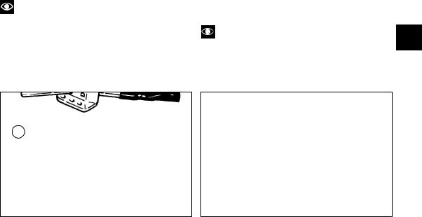
Keys (fig. 5)
Your Ducati was delivered with two universal keys for ignition and steering lock and a key identification plate
(1).
Note
Separate the two keys and keep the identification plate in a safe place.
fig. 5
Ignition switch and steering lock (fig. 6)
It is located in front of the steering head and has four positions:
A)ON: lights and engine on;
B)OFF: lights and engine off;
C)LOCK: steering lock;
D)P: parking light and steering lock.
Note
To move the key to the last two positions, press it E down before turning it. Switching to (B), (C) and (D), you
will be able to take the key out.
fig. 6
13
|
Left switch (fig. 7) |
|
|
|
|
|
||
|
1) Switch, light switch, 3 positions: |
|
|
|
|
|
||
|
Down |
= light off; |
5 |
1 |
|
|
|
|
|
Centre |
= front and rear parking light, number plate |
|
|
|
|||
|
light and panel lights on; |
|
|
|
|
|
||
|
Up |
= headlamp, front and rear parking lights, number |
|
|
|
|
|
|
|
plate light and panel lights on. |
|
|
|
|
|
||
|
|
|
|
|
|
|||
E |
2) Light dip switch, two positions: |
|
|
2 |
|
|||
|
position |
= low beam on; |
|
|
|
|||
|
position |
= high beam on. |
|
4 |
3 |
|
||
|
3) Switch |
= 3-position turn indicator: |
|
|
||||
|
|
|
|
|
||||
|
centre position = OFF; |
|
|
|
fig. 7 |
|
||
|
position |
= left turn; |
|
|
|
|
|
|
|
|
|
|
|
|
|||
|
position |
= right turn. |
|
|
|
|
|
|
To cancel turn indicators, return switch to central position and push in.
4)Button  = warning horn.
5)Button 
 = high-beam flasher.
14
Clutch lever (fig. 8)
Lever (1) disengages the clutch. It features a dial adjuster
(2) for lever distance from the twistgrip on handlebar. To set lever distance from twistgrip, push lever (1) fully forward and turn the dial adjuster (2) to one of its four
positions. Remember that position no. 1 gives maximum distance between lever and twistgrip, whereas lever and twistgrip are closest when adjuster is set to position
no. 4.
When you pull in the lever (1), you will disengage the engine from the gearbox and therefore from the driving wheel. Using the clutch properly is essential to smooth riding, especially when moving off.
Warning
Set clutch and brake levers when motorcycle is stopped.
Important
Using the clutch properly will avoid damage to transmission parts and spare the engine.
3
2 |
A |
1
B
E
fig. 8
Fast-idle lever (fig. 8)
Use this device to start the engine from cold. It will increase the engine idling speed after starting. Lever positions:
A)(vertical) = closed
B)= fully open.
The lever can be opened and closed gradually to adjust speed until engine is fully warm (see page 27).
Important
Never use the fast-idle lever when the engine is warm or leave it open when riding.
15
Right switch (fig. 9)
1) ENGINE STOP switch, two positions: position  (RUN) = run.
position  (OFF) = stop.
Warning
This switch is mainly intended for use in emergency cases when you need to stop the engine quickly. After
E |
stopping the engine, return the switch to the |
position |
to enable starting. |
|
|
|
|
|
Important
When you have been riding with the lights on, and you stop the engine using switch (1) and leave the ignition key in the ON position, the lights will remain on and the battery may run flat.
2) Button  = engine start.
Throttle twistgrip (fig. 9)
The twistgrip (3) on the right handlebar controls the throttles. When released, it will spring back to the initial position (idling speed).
Front brake lever (fig. 9)
Pull in the lever (4) towards the twistgrip to operate the front brake. The system is hydraulically operated and you just need to pull the lever gently.
The control lever is provided with a dial adjuster (5) for lever distance adjustment from twistgrip on handlebar.
Warning
Please read the instructions on page 26 before using these controls.
4
5
1 3
2
16
Rear brake pedal (fig. 10)
Push down on the pedal (1) to apply the rear brake. The system is hydraulically operated.
1
fig. 10
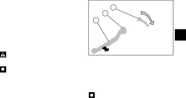
Gear change pedal (fig. 11.1) |
|
The gear change pedal is at rest when in the central |
|
position N, is moved up and down to change gears and |
|
returns to the central position automatically. |
|
down = push down on the pedal to engage 1st gear and |
|
to shift down. The N light will go out. |
|
up = lift the pedal to engage the 2nd gear and then the 3rd, |
|
4th, 5th and 6th gear. |
|
Each time you move the pedal you will engage the next |
E |
gear. |
N
fig. 11.1
17

Setting the gear change pedal (fig. 11.2)
The gear change and rear brake pedals can be adjusted to suit the preferred riding position of each rider.
To set the gear change pedal,
lock linkage (1) and loosen the check nuts (2) and (3).
Note
Nut (2) has a left-hand thread.
E
Rotate linkage (1) until setting the gear change pedal in the desired position.
Tighten both check nuts onto linkage.
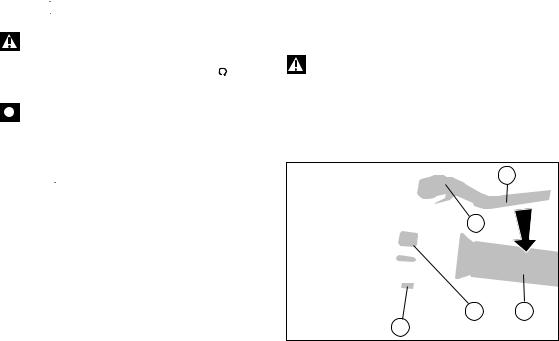
Setting the rear brake pedal (fig. 11.3) To set the rear brake pedal,
loosen check nut (4).
Turn the pedal travel adjusting screw (5) until pedal is in the desired position.
Tighten check nut (4).
Work pedal by hand to make sure it has 1.5 - 2 mm free play before brake begins to bite.
If not so, set the length of master cylinder linkage as follows.
Loosen the check nut (6) on master cylinder linkage. Tighten linkage into fork (7) to increase play, or unscrew linkage to reduce it.
Tighten check nut (6) and check pedal free play again.
fig. 11.2
6
7
4
5 |
fig. 11.3 |
18

MAIN COMPONENTS AND DEVICES |
|
|
|
|
|
|
|
|
4 |
5 |
|
|
|
Location (fig. 12) |
|
|
5 |
|
|
|
|
|
|
E |
|||
1) |
Tank filler plug. |
|
|
|
||
|
|
|
|
|||
2) |
Steering damper. |
|
|
|
|
|
3) |
Side stand. |
|
|
|
|
|
4) |
Rear view mirrors. |
|
|
|
|
|
5) |
Rear shock absorber adjusters. |
|
|
|
|
|
6) |
Exhaust silencer (see note on page 29). |
|
|
|
|
|
|
|
|
|
3 |
|
|
|
4 |
1 |
|
6 |
|
|
|
|
|
|
|
|
|
|
|
|
|
|
|
|
|
|
|
|
|
|
|
|
|
|
|
|
|
|
4 |
2 |
6 |
fig. 12
19
Tank filler plug (fig. 13)
Opening
Place the palm of your hand on the plug (1) and turn anticlockwise.
Closing
Turn the plug (1) clockwise with the palm of your hand and tighten it properly.
E
Warning
Always make sure you have properly refitted (see page 28) and closed the plug after each refuelling.
fig. 13
Side stand (fig. 14)
Important
Before lowering the side stand, make sure that the ground surface is hard and flat.
Do not park on soft or pebbled ground or on asphalt melted by the sun heat and similar or the motorcycle may fall over.
When parking in downhill road tracts, always park the motorcycle with its rear wheel facing downhill.
To pull down the side stand, hold the motorcycle handlebar with both hands and push down on the stand
(1) with your feet until it is fully extended. Tilt the motorcycle until the side stand is resting on the ground.
When the motorcycle is put upright again, the side stand will spring back automatically to rest position.
Check spring for damage or loss of spring and make sure nothing obstructs side stand assembly motion.
Warning
Do not sit on the motorcycle when it is supported on the side stand.
Warning
Make sure the side stand is up before moving off. If still down, the side stand will foul foot controls operation and – worse yet – may dig into the ground in a bend and make you lose control of the motorcycle, resulting in a severe accident or damage to motorcycle.
20
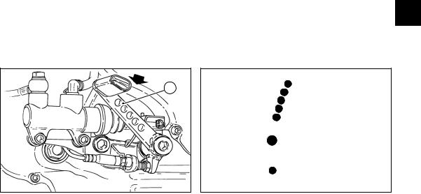
Shock absorber adjusters
The shock absorber is equipped with outer adjusters that enable you to adjust your motorcycle to the load.
The ring nut (1) located on the bottom connection holding the shock absorber to the swingarm, controls rebound damping.
The knob (2) located over the shock absorber expansion reservoir (3) controls compression damping. To adjust damping, rotate ring nut (1) and knob (2):
- towards "soft" for softer damping E - towards "hard" for harder damping.
1 |
fig. 14 |
|
 2
2
3
fig. 15
21
STANDARD setting:
-Ring nut (1) is turned all the way towards "hard". Rotate towards "soft" and count 10 clicks.
-Knob (2) is turned all the way towards "hard". Rotate towards "soft" and count 5 clicks.
Warning
Use a specific pin wrench only to turn the preload adjusting ring nut. Be careful when turning the ring nut E with the wrench, as the pin may slip out of the ring nut
recess and you may hurt your hand hitting motorcycle parts.
The shock absorber is filled with gas under pressure and may cause severe damage if taken apart by unskilled persons.
Adjust spring preload to suit your weight and that of any load you are carrying, so to obtain constant clearance from the ground. You may find that rebound damping needs readjusting.
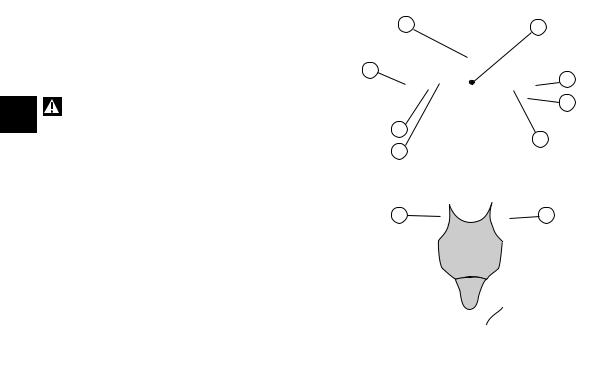
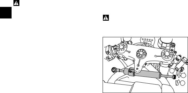
Steering damper (fig. 16)
The steering damper is before the tank and is secured to the frame and the steering head.
It gives improved steering accuracy and stability, thus also improving motorcycle road behavior under any riding conditions.
Turn the knob (1) clockwise for a harder setting (2), counter clockwise for a softer setting (3).
A click identifies the different settings.
Warning
Never attempt to set knob (1) while riding, or you may lose control of the motorcycle.
1 |
3 |
2 |
fig. 16 |
22
 Loading...