


|
® |
INSTALLATION AND |
|
|
OPERATING INSTRUCTIONS |
|
|
REFRIGERATOR FOR LP-GAS AND ELECTRIC OPERATION
RM2454
FOR YOUR SAFETY
If you smell gas:
1.Open windows.
2.Don’t touch electrical switches.
3.Extinguish any open flame.
4.Immediately call your gas supplier.
FOR YOUR SAFETY
Do not store or use gasoline or other flammable vapors and liquids in the vicinity of this or any other appliance.
WARNING: Improper installation, adjustment, alteration, service or maintenance can cause injury or property damage. Refer to this manual. For assistance or additional information consult a qualified installer, service agency or the gas supplier.
Contents: |
|
|
Page |
Installation |
4 |
Operating Instructions |
8 |
Maintenance & Service |
12 |
Pour votre sécurité
Si vous sentez une odeur de gaz:
1.Ouvrez les fenêtres.
2.Ne touchez à aucun interrupteur.
3.Éteignez toute flamme nue.
4.Avertissez immédiatement votre fournisseur de gaz.
Pour votre sécurité
Ne pas entreposer ni utiliser de l’essence ni d’autres vapeurs ou liquides inflammables à proximité de cet appareil ou de tout autre appareil.
Avertissement: Une installation, un réglage, une modification, une réparation ou un entretien non conforme aux normes peut entraîner des blessures ou des dommages matériels. Lisez attentivement le mode d’emploi fourni avec l’appareil. Pour obtenir de l’aide ou des renseignements supplémentaires, consultez un installateur ou un service d’entretien qualifié ou le fournisseur de gaz.
®
USA |
Corporate Office |
CANADA |
Service Office |
2320 Industrial Parkway Elkhart, IN 46515 |
Dometic Distribution Inc. |
Dometic Corporation |
|
866 Langs Drive |
509 South Poplar Street |
|
Cambridge, Ontario |
LaGrange, IN 46761 |
For Service Center Assistance |
N3H 2N7 Canada |
Phone: 260-463-4858 |
Call: 800-544-4881 |
Phone: 519-653-4390 |
|
|
|
822709202 (French 3309243.008) |
|
|

Heaters
Reigniter
Flue baffle
Relay
Power module cover
Protection cover
12V DC
FIG. 1 |
|
Screw for protection cover |
|
12 volt |
Burner jet |
||
|
|||
|
|
||
|
Terminal block |
Manual gas shutoff valve |
|
|
|
||
|
|
Inlet fitting |
|
Flexible cord |
|
Drain water hose |
|
|
|
Refrigerator control panel |
A |
D |
|
E |
ON |
DC |
AUTO |
COLD 1 2 3 4 5 COLDEST |
1 |
2 |
3 |
4 |
OFF |
AC |
GAS |
CHECK |
B |
C |
|
F |
LEGEND 3-WAY AMES Model
1. Main Power Button ON/OFF
2. DC Mode Selector Button
3. AUTO/GAS Mode Selector Button
4. Temperature Selector Button
A. DC Mode Indicator Lamp
B. AC Mode Indicator Lamp
C. GAS Mode Indicator Lamp
D. AUTO Mode Indicator Lamp
E. CHECK Indicator Lamp
(GAS Mode Only)
F. Temperature Indicator Lamps
FIG. 2
3
INSTALLATION
GENERAL INSTRUCTION
This appliance is designed for storage of foods and storage of frozen foods and making ice.
This appliance is certified under the latest edition of ANSI Z21.19•CSA 1.4 Refrigerators using gas fuel.
The installation must conform with local codes, or in absence of local codes, the following standards as applicable.
In the U.S. the installation must conform with:
1.National Fuel Gas Code, ANSI Z223.1/NFPA 54 (latest edition).
2.Recreational Vehicles Code, ANSI A119.2 (latest edition)
3.Manufactured Home Construction and Safety Standard, Title 24 CFR, Part 3280.
If an external electrical source is utilized, the refrigerator, when installed, must be electrically grounded in accordance with local codes or, in the absence of local codes, the National Electrical Code, ANSI/NFPA 70 - (latest edition).
In CANADA, the installation must conform with:
1.Natural Gas and Propane Installation Code, CSA B149.1
2.CSA Z240 RV Series, Recreational Vehicles.
3.Current CSA Z240.4, Gas-equipped Recreational Vehicles and Mobile Housing.
If an external electrical source is utilized, the refrigerator, when installed, must be electrically grounded in accordance with local codes or, in the absence of local codes, the Canadian Electrical Code, CSA C22.1, Parts I and II - (latest edition).
VENTILATION
The installation shall be made in such a manner as to separate the combustion system from the living space of the mobile home or recreational vehicle. Openings for air supply or for venting of combustion products shall have a minimum dimension of not less than 1/4 inch.
Proper installation requires one lower fresh air intake and one upper exhaust vent. The ventilation kits shown in this instruction manual have been certified for use with the refrigerator models listed in the Table.
For “Certified Vent System Kits” see page 15.
The ventilation kits must be installed and used without modification. An opening toward the outside at floor level in the refrigerator compartment must be provided for ventilation of heavier-than-air fuel gases. The lower vent of the recommended kits is provided with proper size openings. The flow of combustion and ventilating air must not be obstructed.
The lower side vent is fitted with a panel, which provides an adequate access opening for ready serviceability of the burner and control manifold of the refrigerator. This should be centered on the back of the refrigerator.
CERTIFIED INSTALLATION
Certified installations require one roof vent and one lower side vent.
For “Certified Vent System Kits” see page 15.
For further information contact your dealer or distributor.
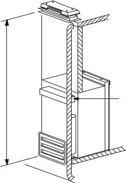
METHODS OF INSTALLATION
The method of installation is shown in FIG. 3.
It is essential that all maximum or minimum dimensions are strictly maintained, as the performance of the refrigerator is dependent on adequate flow of air over the rear of the refrigerator.
NOTE: The upper vent should be centered over the condenser coil at the back of the refrigerator.
Minimum ventilation height
Condenser
FIG. 3
4
VENTILATION HEIGHTS
Refer to FIG. 3 page 4.
Installation with roof |
Minimum ventilation |
|
vent and lower side vent |
heights in: |
|
|
|
|
Refrigerator |
Inches |
mm |
RM 2454 |
|
|
37-3/4 |
960 |
|
|
|
|
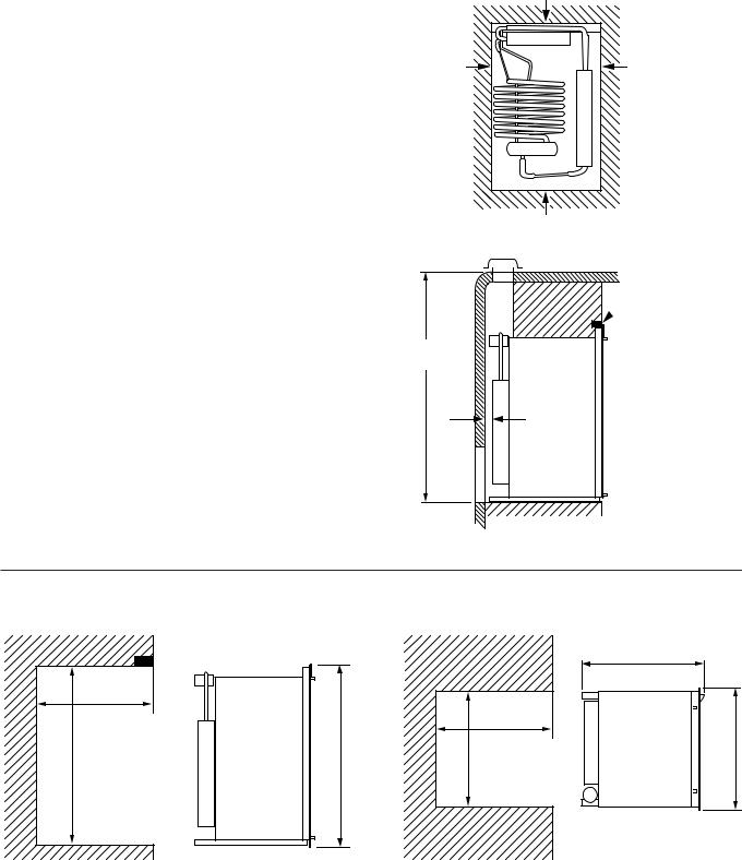
CLEARANCES
Minimum clearances in inches to combustible materials
are: |
|
|
G: |
Top |
0 |
K: |
Side |
0 |
L:Bottom 0
M:Rear 0
N:See NOTE: Clearance “N” below.
NOTE: Clearance “M” is between the rearmost part of the refrigerator and the wall behind the refrigerator.
NOTE: Clearance “N” is the distance between the bottom of the lower side vent to the roof material. For ventilation height, see table VENTILATION HEIGHTS.
See Figures 3 and 4.
|
G |
K |
K |
FIG. 4 |
L |
|
NOTE: Wood Strip
 MUST be in place
N
M
FIG. 5
Side view |
View from above |
|
|
|
C |
|
D |
|
|
|
|
|
D |
H |
A |
W |
B |
|
|
Overall |
|
|
|
Recess |
|
|
Refrigerator |
|
Dimensions |
|
|
Dimensions |
|
||
Model |
|
|
|
|
|
|
|
|
|
Height |
Width |
|
Depth |
Height |
|
Width |
Depth |
|
A |
B |
|
C |
H |
|
W |
D |
inch |
37-3/8 |
24-7/8 |
|
24-11/16 |
36-9/16 |
|
23-11/16 |
24 |
RM 2454 |
|
|
|
|
|
|
|
|
mm |
948 |
632 |
|
627 |
928 |
|
602 |
610 |
This method of installation and these clearances will give you adequate space for service and proper installation.
5
 Loading...