


OPERATING AND INSTALLATION INSTRUCTIONS FOR DOMETIC REFRIGERATORS
TYPE: A30-80K
MODEL RM 123E
(Bottled Gas and 12/230 Volt Operation)
MODEL RM 122F
(Bottled GAS AND 12 Volt Operation)
207.4495.02
0402

IMPORTANT USER INFORMATION
It most important that this instruction book should be retained with the appliance for future reference. Should the appliance be sold or transferred to another owner, always ensure that the book is supplied with the appliance in order that the new owner can be acquainted with the functionning of the appliance and the relevant warnings.
These warnings are provided in the interest of safety. You must read them carefully before installing or using the appliance.
This product is designed to be operated by adults. Children should not be allowed to tamper with the controls or play with the product.
Any electrical work required to install this appliance should be carried out by a qualified electrician.
This product should be serviced by an authorised Service Engineer and only genuine spare parts should be used.
It is dangerous to alter the specifications or modify this product in any way.
Care must be taken to ensure that the appliance does not stand on the electrical supply cable.
These refrigerators are designed to be used specifically for the storage of edible foodstuffs only.
There are workings parts in this product which heat up. Always ensure that there is adequate ventilation as a failure to do this will result in component failure and possible food loss. See installation instruction.
Parts which heat up should not be exposed. Wherever possible the back of the product should be close to a wall but leaving the required distance for ventilation as stated in the installation instructions.
Before defrosting, cleaning or maintenance work is carried out, be sure to switch off the appliance and unplug it.
The ice box in this appliance contains tubes through which the refrigerant passes. If these are punctured this would cause substantial damage and result in food loss. DO NOT USE SHARP INSTRUMENTS to scrape off frost or ice. Under no circumstances should solid ice be forced off the ice box. Solid ice should be allowed to thaw when defrosting the appliance. See defrost instructions.
The appliance should be left for 2 hours after installation before it is turned on in order to allow refrigerant to settle, unless it is of the absorption type in which case it can be turned on immediately.
This appliance is heavy. Care should be taken when moving it.
Ice lollies can cause frost burns if consumed straight from the freezer.
Frozen food must not be refrozen once it has thawed out.
Manufacturers' food storage recommendations should be strictly adhered to. Refer to relevant instructions.
Do not place carbonated or fizzy drinks in the freezer as it creates pressure on the container which may cause it to explode resulting in damage to the appliance.
Under no circumstances should you attempt to repair the appliance yourself. Repairs carried out by inexperienced persons may cause injury or more serious malfunctioning. Refer to your local Service Centre and always insist on genuine spare parts.
GENERAL GUIDE TO FITTING ANY PLUG
Ensure the lengths of wire inside the plug are prepared correctly.
Connections should be firmly made after all conductor strands are entered into the terminal posts.
When preparing the cable ends take care not to damage the outer sheath, or the insulation surrounding the inner conductors.
Tighten all screws.
Replace the top cover of the plug and secure.
INSTRUCTIONS FOR INSTALLATION
1. INTRODUCTION
Before starting to install the refrigerator, please read these instructions carefully in order to obtain a thorough understanding of what is required.
When operating, heat is emitted from parts of the cooling unit at the rear and this has to be carried away by air circulating freely over the back of the refrigerator. To ensure sufficient air circulation for satisfactory operation. It is essential that the clearances called for in these instructions are not reduced in any way otherwise cooling performance will be impaired. Providing the refrigerator is installed in accordance with these instructions, it should operate satisfactorily in ambient temperatures up to 32°C (90°F), with some measure of cooling up to about 35°C (95°F).
It is recommended that the refrigerator is installed by the caravan manufacturer, the supplier or another qualified person Owners who are competent to carry out the work themselves can do so, but, for the sake of safety, they must take particular care in making the gas connections, checking for leaks, and installing the electrical wiring and fittings. All relevant regulations concerning such installations must be complied with.
Many caravans are already provided with a recess, usually in the form of a cupboard which has been specially designed so that it can be adapted, by removal of its door and shelves, to house a refrigerator. Some caravan manufacturers have also devosed kits of parts to aid installation of refrigerators in their particular caravans.
A ventilator for fitting above the door as shown in fig. 4 is supplied with the refrigerator. The connection pipe, gas cock, and connectors are not supplied as the sizes of these may vary to suit particular installations. The appropriate parts should, however, be readily available from the refrigerator supplier or an Agent dealing in gas fittings 9see note in item 11).
The refrigerator weighs approximately 14,5 kg (321b) and the surface on which it is installed must be capable of carrying this weight, plus that of the food, satisfactorily.
All surfaces above and adjacent to the flue outlet, and beside and below the burner housing should be of, or covered with, metal or other non-flammable material.
IMPORTANT: On motorised vehicles, the refrigerator must be installed well away from fuel tanks, fuel filling inlets, pipes leading from inlets to fuel tanks, and fuel tank breathers.
WARNING:
Because of the hazards associated with the use of continuous operating bottled-gas appliances with open-flame burners in difficult-to-ventilate confined spaces, and other considerations, Dometic RT do not recommend the installation of their bottled-gas caravan refrigerators on boats, and refrigerators so installed will not be covered by the Company's guarantee.
If, however, a boat installation is planned for the refrigerator, reference should be made to British Standard 5482 Part 3, 1979 and to the Thames Water Authority "Launch Digest" and "Launch Specification".
Also, current Guide Lines published by local Water Authorities, or the Ship and Boat Builders' National Federation.
It should be noted that special Marine Refrigerators are available from Electrolux for use on boats.
2. VENTILATION
The refrigerator will always be built into a recess but to enable the unit to operate efficiently, it is essential that air is allowed to circulate freely over the cooling unit at the back to carry away the heat generated during the cooling process 9see fig. 10. The minimum free spaces called for under, behind and over the cabinet must not, therefore, be reduced in any way. The more space provided, particulary behind and over the cabinet, the better the performance you can expect from the cooling unit.
2

ventilator located at top rear.
|
|
ventilator located |
at |
|
|
|
|
top front |
|
|
|
|
|
|
|
Flue Outlet |
|
Flue Outlet |
|
|
|
||
|
|
|
|
||
|
|
|
|||
|
|
|
|
|
|
|
|
|
|
|
|
(a) |
(b) |
Arrows indicate air-flow to ventilate cooling unit at rear
Fig. 1
3. IMPORTANCE OF LEVELLING |
7. BUILDING-IN |
The downward circulation of refrigerant within the cooling unit is by gravity and the refrigerator has to be reasonably level, when it is stationary, for the cooling unit to operate properly. If the refrigerator is left operating with a sustained list in excess of about 3º in any direction, pockets of liquid refrigerant can collect at various points within the unit impairing or preventing normal circulation of the refrigerant vapour until level conditions return.
It is essential, therefore, that the refrigerator is installed so that the ice-tray shelf inside the refrigerator is level in relation to the caravan, in both directions, so that when the caravan is level, the ice-tray shlef is level.
4. CHANGING DOOR HINGES TO OPPOSITE SIDE
The refrigerator is manufactured with the door hinged on the right hand side, however, it can be changed to left hand opening if required.
Gently place the refrigerator on its back (taking care not to damage the burner assembly0, pull off the gas control knob, then remove the lower ventilator by taking out the screws from each end.
Remove upper hinge blade and travel catch blade from top of cabinet. Fit the upper hinge blade and travel catch blade to their new positions on the top of the cabinet and transfer the lower hinge blade to the opposite side. Refit the ventilator by means of the screws, then push the gas control knob onto its spindle so that the flat on the spindle engages the flat in the recess of the knob.
5. CHANGING OUTER DOOR PANEL
If required, the outer door panel can be removed and replaced by one of a different material or colour to match other fitments.
I can be of rust proof metal or plastic laminate.
To do this lay the refrigerator on its back, and remove the bottom section of the door frame held by 3 screws. The existing panel can then be slid out and a new panel slid in, and the bottom section refitted to retain the new panel.
The replacement panel should be from 0,5 mm to 3 mm thick, and 350 mm wide x 485 mm high.
While the refrigerator is built-in, adequate space must be left under, over and behind it to allow a sufficient circulation of air over the cooling unit at the back for satisfactory operation. The recommended method of building-in is shown in fig. 5, with the upper ventilator at the front. However, where space limitations do not permit the upper ventilator to be fitted at the front, the alternative arrangement shown in fig. 6 may be adopted and the height of the recess reduced accordingly. A work-surface can then be fitted over the top front of the refrigerator, but it must not over-hang the door where it could interfere with the operation of the travel catch.
Securing in the Recess
The refrigerator must be secured in the recess to prevent movement. A suggested method of securing is by means of metal brackets about 20 mm (3/4") wide, (which should be made to suit the particular installation), screwed to the rear of the refrigerator by means of the two existing cooling unit fixing screws (fig. 2) and to the rear wall of the caravan
6. DIMENSIONS OF REFRIGERATOR |
Fig. 2 |
The exterior dimensions of the refrigerator are given in fig. 3.
For dimensions of the recess to house the refrigerator when buildingin, refer to item 7.
3
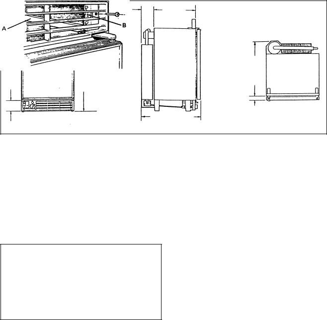
73 mm |
100 mm |
300 mm |
|
7 |
|
||
(2 /8") 380 mm (15") |
(4") |
(11 13/16") |
|
") |
") |
|
|
16 |
16 |
|
|
1/ |
15/ |
|
|
510 mm (20 |
659 mm (25 |
|
") |
|
16 |
||
|
400mm (15 13/ |
||
|
|
|
39 mm |
|
|
439 mm (17 5/ ") |
( 1 1/2") |
|
|
16 |
|
Fig. 3
Alternatively, wooden battens may be screwed to the sides of the recess, from front to back, bearing down on the top of the cabinet to hold it firmly, as shown at A, fig. 4. Whichever method is used, it must be possible to remove the refrigerator easily for subsequent servicing purposes. The brackets or battens must be in a position where they will not restrict the air circulation over the cooling unit; they must not be positioned across the cabinet over the fins of the condenser of the cooling unit at the rear, otherwise air-flow will be impaired and performance affected.
Fitting the Upper Ventilator
To fit the upper ventilator, screw a block of wood approx. 25 mm (1") square x 66 mm (2 5/8) long. to each side of the recess, 16 mm (5/8") back from the front edge, as shown at B, fig. 4. Secure the ventilator to the blocks with a screw through the hole provided at each end.
|
|
B |
|
A |
|||
|
|
||
|
|
||
|
|
|
Fig. 4
Additionnal Ventilator
To reduce the amount of heat entering the caravan, particularly when used in warner climates, an additionnal ventilator (A, fig. 5), may be fitted in the wall of the vehicle, preferably above the level of the top of the refrigerator. (The exterior flue venting kit must still be used).
All surfaces above and adjacent to the flue outlet, and beside and below the burner housing should be of, or protected by, metal or other inflammable material.
8. VENT HOLE UNDER REFRIGERATOR
A ventilation hole of not less than 13 cm2 (2in2) effective area (40 mm or 1 5/8" diameter) must be provided in the floor below the refrigerator as shown in fig. 5. The hole should lead directly to the outside air through the floor or wall so that, in the event of a gas leak, it would provide an escape outlet for the heavier-than air gas. It should not be too close to the burner where draught could affect the flame.
On mobile installations, the vent hole should be shielded against entry of mud etc., by a deflector as shown in fig. 5a, fitted underneath with its "closed" end facing the front of the vehicle. The deflector should be made from a suitable piece of metal, to suit the particular installation.
9. FLUE ARRANGEMENT
Flue Baffle
The flue baffle (4, fig. 10) must be in position in the central tube of the boiler, suspended on its support wire so that the lower end of the baffle is 75 mm (3") above the bottom of the central tube over the burner. The top end of the baffle support wire is bent into the shape of an "O" and rests horizontally on the tp of the central tube. The baffle is correctly positioned during the manufacture ans should not become displaced during normal use. If the flue baffle is missins or is incorrectly located, the cooling unit will not operate properly on gas. Any strapping tape used to retain the baffle support wire to the top of the boiler casing during transit should be removed before installation.
Flue Venting Kit
The flue gasses must be vented directly to the outside air. Only the flue venting kit (supplied with the refrigerator in the United Kingdom) is recommended for this purpose. It consists of the following parts:
Flue Top Complete-G Flue Outlet Cover Plate-B
Exhaust Gas Pipe Complete-F Screw-sELF tAPPING. nO. 6 X 1/4in-H
The flue top (G) is in the form of a lazy "T" and incorporates an air-break to minimise the possibility of flame extinction due to draughts.
Leading from the flue-top, the extension tube (F) has to pass through the wall of the vehicle to direct the flue gasses to the outside. Care must be taken in determining the positions of the centres of the holes in the inner and outer skins of the caravan wall to accept the extension tube. As the amount of space between the back of the refrigerator and the inside wall og the vehicle as well as the thickness of the wall, may vary for each type of caravan, it is not possible to give actual dimensions therefore each case must be considered carefully before starting to make the opening. Take particular care to ensure that the angle is correct so that when in position, the extension tube will line up accurately with the sloping part of the flue-top.
The opening mus be large enough to allow the insertion of a layer of non-combustible material around the extension tube as shown in fig. 7, but the opening in the outer skin must not exceed 70 mm (2 3/4") in diameter, otherwise the flange on the flue outlet may not cover it completely.
4
 Loading...