


Model CP65
Cinema Processor
Installation and Alignment
Instructions
Issue 4 |
Part No. 91234 |

Model CP65 Cinema Processor Installation and Alignment Instructions
Dolby Laboratories Inc
U.S. Headquarters
Dolby Laboratories Inc
100 Potrero Avenue
San Francisco, CA 94103-4813 Telephone 415-558-0200 Facsimile 41-863-1373 www.dolby.com
U.K. European Office
Dolby Laboratories Inc
Wootton Bassett
Wiltshire SN4 8QJ England
Telephone (44) 1793-842100
Facsimile (44) 1793-842101
DISCLAIMER OF WARRANTIES: Equipment manufactured by Dolby Laboratories is warranted against defects in materials and workmanship for a period of one year from the date of purchase. All warranties, conditions or other terms implied by statute ar excluded to the fullest extent allowed by law.
LIMITATION OF LIABILITY: It is understood and agreed that Dolby Laboratories’ liability whether in contract, in tort, under any warranty, in negligence or otherwise shall not exceed the cost of repair or replacement of the defective components and under no circumstances shall Dolby Laboratories be liable for incidental, special, direct, indirect or consequential damages (including but not limited to damage to software or recorded audio or visual material), or loss of use, revenue or profit even if Dolby Laboratories or its agents have been advised, orally or in writing, of the possibility of such damages.
Dolby and the double-D symbol are registered trademarks of Dolby Laboratories. |
|
©1999 Dolby Laboratories Inc |
Issue 4 |
|
|
|
S99/9563/12772 |
|
Part No. 91234 |
ii

Model CP65 Cinema Processor Installation and Alignment Instructions
|
Table of Contents |
|
INTRODUCTION ............................................................................................................. |
v |
|
CP65 ............................................................................................................................ |
v |
|
CP65-A ........................................................................................................................ |
v |
|
CP65-300..................................................................................................................... |
v |
|
About this manual....................................................................................................... |
v |
|
SECTION 1 |
|
|
EQUIPMENT REQUIRED .......................................................................................... |
1-1 |
|
SECTION 2 |
|
|
INITIAL SET-UP AND INSTALLATION .................................................................... |
2-1 |
|
Wiring Diagrams .................................................................................................... |
2-3 |
|
Jumpers on Boards |
|
|
|
Cat. No. 441. .................................................................................................... |
2-5 |
|
Cat. No. 242. .................................................................................................... |
2-6 |
|
Cat. No. 249 ..................................................................................................... |
2-6 |
|
Cat. No. 443 ..................................................................................................... |
2-7 |
|
CP65 Backplane............................................................................................... |
2-8 |
|
Cat. No. 241 ................................................................................................... |
2-10 |
Card Descriptions ................................................................................................ |
2-11 |
|
IEC Notices .......................................................................................................... |
2-15 |
|
Hum Problems ..................................................................................................... |
2-16 |
|
SECTION 3 |
|
|
AN OVERVIEW OF THE ALIGNMENT PROCEDURE ............................................. |
3-1 |
|
1. |
Aligning the A-Chain ........................................................................................ |
3-1 |
2. |
Aligning the B-Chain ........................................................................................ |
3-1 |
SECTION 4 |
|
|
A-CHAIN ALIGNMENT .............................................................................................. |
4-1 |
|
a. Preliminary Procedures.................................................................................... |
4-2 |
|
b. Optical Preamplifier Adjustments ................................................................... |
4-6 |
|
c. Magnetic Preamplifier Adjustments .............................................................. |
4-20 |
|
SECTION 5 |
|
|
B-CHAIN ALIGNMENT .............................................................................................. |
5-1 |
|
a. Setting Room Equalization .............................................................................. |
5-2 |
|
b. Adjusting L,C,R Gain ..................................................................................... |
5-18 |
|
c. Setting Mono Gain ......................................................................................... |
5-20 |
|
d. Subwoofer Alignment .................................................................................... |
5-22 |
|
e. Surround Equalization Alignment .................................................................. |
5-32 |
|
f. Adjustment of Surround Delay ...................................................................... |
5-42 |
|
g. Adjustment of Bypass Gain ........................................................................... |
5-44 |
|
h. Adjustment of Non-sync Gain ....................................................................... |
5-48 |
|
i. Adjustment of Mono Gain and Equalization ................................................. |
5-52 |
|
j. |
Final Checks ................................................................................................... |
5-54 |
iii

Model CP65 Cinema Processor Installation and Alignment Instructions
SECTION 6 |
|
REFERENCE BLOCK DIAGRAMS .......................................................................... |
6-1 |
APPENDIX A
Checking Phasing of Speakers
APPENDIX B
Effect of Changes in Slit Height on Slit Losses
APPENDIX C
CP65M (Mono) Instructions
APPENDIX D
Backplane Connections Listing
iv

v
INTRODUCTION
This manual contains essential information on the installation and alignment of the CP65 Cinema Sound Processor. The CP65 supersedes the CP55 and is available in three versions:
CP65
The standard configuration, equipped for the reproduction of the following sound formats
•01 Mono–for all optical prints of any vintage with conventional mono optical (“Academy”) sound-tracks.
•04 Dolby Stereo A-type
•05 Dolby Stereo SR
• 10 Dolby Stereo Digital-with the addition of an external digital adapter
•60 Non-sync
•Mag / Aux–This format may be programmed in a number of different ways. Possible options include:
•Magnetic sound-tracks without A-type noise reduction.
•Extra sound sources, such as a Magnetic follower/dubber, PA microphone with preamp or a “stereo” synthesizer.
CP65-A
Equipped with A-type noise reduction only. Reproduces the same formats as the standard CP65 with the exception of 05 Dolby Stereo SR.
CP65-300
Equipped with two Cat. No. 300 modules in place of the Cat. No. 350 SR modules. Cat. No. 300 SR/A processors contain both A-type and SR circuits and these additional two channels of A-type along with the channels in the Cat. No. 222 modules are used to decode 70 mm Dolby Stereo magnetic soundtracks (format 42).
About this manual
This manual is intended to be used by individuals who are qualified in the area of cinema sound service. The basic day-to-day operation of the CP65 is covered in the CP65 Operator’s Guide.

vi
This installation and alignment manual covers the procedures necessary to ensure that the theatre sound system is accurately aligned to standards that have been established by Dolby Laboratories. Following these procedures will ensure that the theatre sound system will accurately reproduce the soundtrack as the director and sound mixers intended.
The Dolby Cinema Processor is the central element of the theatre sound system. The projector, the Dolby Processor, the power amplifiers and the loudspeakers, as well as the auditorium itself, must be considered when aligning the system for optimum performance.
The system alignment procedure is divided into two parts—the A-chain alignment which covers the projector, optical preamplifier, and Dolby noise reduction adjustments—and the B- chain alignment which covers the portions of the system from the room equalization circuits to the CP65 fader through to the loudspeakers.
The alignment instructions in this Manual are presented in three columns. The first column, Action, contains a drawing of the item to be adjusted and a caption containing a brief description of the action to be taken. The second column, Indication, contains a visual indication of the desired results, where applicable. The third column, Notes, contains information which amplifies and supplements the other two columns.
If you are familiar with alignment of other Dolby Cinema Processors you need to follow only the information in the first two columns. If you are unfamiliar with the equipment or face special situations that require complete information you should consult the Notes column.
CAUTION
This Installation Manual is for use by qualified personnel only. To avoid electric shock do not perform any servicing other than that contained in the Operator's Guide unless you are qualified to do so.
1-1
SECTION 1
EQUIPMENT REQUIRED
a.Dual-trace oscilloscope with X-Y facilities.
b.1/3 Octave Real Time Spectrum Analyzer (RTA) with calibrated microphone. (Preferably multiple microphones and a multiplexer should be used.)
c.Sound Pressure Level Meter (with slow time-constant and C weighting scale).
d.Cat. No. 85C pink noise generator.
e.Cat. No. 67 extender for the equalizer modules.
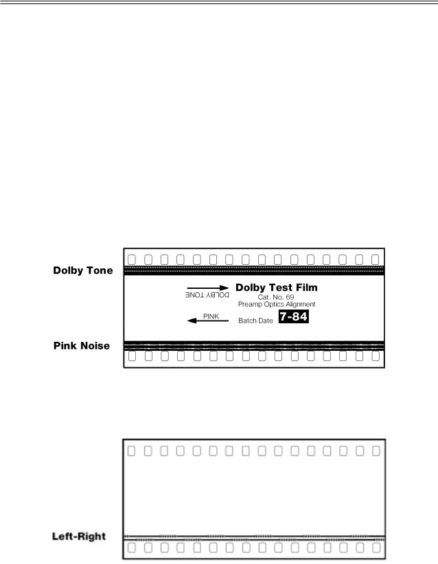
f.Test Films (available from Dolby Laboratories or equipment dealers). We recommend that you make loops of these test films, sufficiently long to go through the entire projector film path so that azimuth and lateral film position adjustments can be made accurately.
(1) Dolby Tone and Pink Noise — Cat. No. 69
(2) 1kHz, 100% Modulation, Left/Right — Cat. No. 97

1-2
(3)SMPTE Buzz Track
(4)Stereo Optical Surround Level — Cat. No. 151
g.The following films can also be purchased from Dolby Laboratories or a cinema equipment dealer. The films are optional items that are used in final system sound verification:
(1) “Jiffy” Test Film — Cat. No. 251 (2) “Listen . . .” Film — Cat. No. 351.
JIFFY |
listen… |
||
TEST FILM |
|||
CN 251–A subjective film for testing theatre sound |
CN 351–The Stereo Demonstration Film |
||
RECORDED IN |
RECORDED IN |
||
DOLBY STEREO |
DOLBY STEREO |
||
Running time: 8 minutes. |
Running time: 8 minutes. |
||
Picture format: 1.85:1 widescreen or |
Picture format: 2.35:1 anamorphic. |
||
|
2.35:1 anamorphic. |
Sound format: |
04 |
Sound format: |
04 |
|
|
|
|
||
|
|
stereo optical |
|
|
stereo optical |
|
with surround |
|
with surround |
Dolby Laboratories, 100 Potrero Avenue, |
|
Dolby Laboratories, 100 Potrero Avenue, |
San Francisco, CA 94103-4813 |
||
San Francisco, CA 94103-4813 |
Telephone 415-558-0200, Telex 34409, Facsimile 415-863-1373 |
||
Telephone 415-558-0200, Telex 34409, Facsimile 415-863-1373 |
Dolby, the Double-D symbol and Dolby Stereo are trademarks |
||
Dolby, the Double-D symbol and Dolby Stereo are trademarks |
of Dolby Laboratories Licensing Corporation. |
||
of Dolby Laboratories Licensing Corporation. |
S89/4784/6776 |
||
S89/4784/8690 |
|
|
|

2-1
SECTION 2
INITIAL SET-UP AND INSTALLATION
Before you remove or replace the Cat. No. 240A Optical Pre-Amp or the Cat. No. 249 Power Supply Card, first disconnect AC power from the CP65 to protect the speakers and the CP65 from damage. For all other modules in the CP65, first switch to BYPASS; you can then safely remove or replace the desired card without disconnecting power from the CP65.
Do NOT connect the CP65 to mains power until all connections have been made and all jumpers have been installed (see STEP 9 later in this section).
STEP 1 If air-conditioning noise is audible in the theatre, arrange for lubrication of the motor, fan bearings, adjustment of belts and drives, and cleaning of filters to reduce the ambient noise to a minimum.
If the CP65 replaces an existing cinema sound system, play a typical film before you remove the old system so you will have a benchmark for comparison to the new system and as a check of the positioning of the exciter lamp, the focusing of the sound track lens, and the condition of the solar cell.
Before you run the film:
•Verify that the existing power amplifiers are in good working order.
•Verify that the existing speakers are in good working order, and that there is no loose or missing hardware or structural members in the enclosures.
•Verify that all wiring is present and properly connected and that crossovers are operating and are correctly adjusted.
•Check the phasing of the speaker connections (see Appendix A).
•Verify that there are adequate earth (ground) connections.
•Verify that radio interference problems are adequately resolved.
STEP 2 While you are running the film, listen carefully in various parts of the theatre for audio system problems:
•Hum.
•Noise, clicks, pops.
•Distortion.
•Poor tonal balance (lack of high-frequency or bass content).
These problems must be resolved before you can proceed to the next step in the installation.
STEP 3 To avoid heat problems, do not locate the CP65 immediately above or below the power amplifiers.
Always leave a 1U (43 mm, 1.75") space above and below the CP65 to provide adequate ventilation. Install an air guide or baffle to deflect hot air from equipment below the CP65.
2-2
Locate the power amplifiers away from the Cat. No. 240A optical preamplifier to avoid hum pickup problems.
STEP 4 Disconnect power from the existing cinema sound equipment.
STEP 5 Disconnect all cabling from the existing cinema sound processing system, but do not disconnect the wiring from power amplifiers, etc.
STEP 6 Check that the CP65 voltage selector switch is set correctly for your mains voltage and that the correct fuses are installed. (The selector switch is located on the rear of the Cat. No. 259 Power Supply and can be seen through the backplane.)
DISCONNECT THE CP65 FROM POWER BEFORE YOU TURN THE SELECTOR SWITCH FROM ONE POSITION TO ANOTHER.
The CP65 accepts both 50 Hz and 60 Hz power. The mains voltages must fall within the following limits:
Voltage |
Acceptable |
|
|
Setting |
Voltage Range |
Fuse |
Type |
100 VAC |
85-110 VAC |
1.25 A |
1/4" x 1-1/4" slow-blow |
120 VAC |
102-132 VAC |
1.25 A |
1/4" x 1-1/4" slow-blow |
140 VAC |
119-154 VAC |
1.25 A |
1/4" x 1-1/4" slow-blow |
200 VAC |
170-220 VAC |
T 630 mA |
5 x 20mm time lag |
220 VAC |
187-242 VAC |
T 630 mA |
5 x 20mm time lag |
240 VAC |
204-265 VAC |
T 630 mA |
5 x 20mm time lag |
NOTE
Follow all local codes and regulations covering electrical wiring. It is recommended that conduit be used for wiring runs.
STEP 7 All signal connections (except those to automation connector J18 -- see the following step) are made by soldering the leads to fanning strips (solder tags) that are supplied with the CP65. The fanning strips with the soldered wiring are fastened in place at the terminal blocks shown on the wiring diagram.
STEP 8 If you plan to make use of the automation interface in the CP65, there are two methods you can follow.
If both remote switches and their accompanying indicators for format, mute, and local / remote fader control are required you should use the 25 way D type connector J18. If only remote switches are required connections can be made to TB1 using the fanning strips supplied with the CP65.
2-5
STEP 9 Next, check the jumpers in the following locations:
Cat. No. 441 Surround Equalization, Subwoofer and SR•D Interface Card (if fitted).
|
Mono Stereo |
|
|
50 Hz |
100 Hz |
|
auto |
|
|
|
|
J4 |
|
|
subwoofer |
J3 |
Surround |
off |
|
|
Optical Subwoofer
Crossover Frequency
Output Level
Range
J1
Low High
Low
High
Subwoofer


 J2 Level Range
Cat. No. 441
The Cat. No. 441 has four jumpers that are used to configure the card to suit the installation in which it is used.
J1 Right Surround output level sets the output gain range for the right surround channel. J1 is set at the factory for a power amplifier input sensitivity of between 90 mV and 1.23 V. If the power amplifiers used in the installation are very sensitive (10 mV to 100 mV input sensitivity), it may be necessary to move this jumper to the low output position.
J2 Subwoofer output level control sets the output gain range for the subwoofer channels. J2 is set at the factory for a power amplifier input sensitivity of between 90 mV and 1.23 V. If the power amplifiers used in the installation are very sensitive (10 mV to 100 mV input sensitivity), it may be necessary to move this jumper to the low output position.
J3 Surround Mono / Stereo selects stereo or mono surround operation. Set J3 to the Stereo position if your cinema is equipped with separate power amplifiers and speaker wiring for left and right surrounds. Note that stereo surround signals are only available in format 10 Dolby Stereo digital. Install this jumper in the stereo or mono position according to your installation.
J4 Subwoofer upper frequency limit sets upper frequency limit of the subwoofer channel in optical or non-sync to either 50 or 100 Hz. The recommended setting of this jumper depends on the type of screen speakers in your cinema.
If you have the older horn-loaded type of speaker (such as Altec A-4), the jumper should be set for 100 Hz and the equalization for the screen speakers rolled off below this frequency. These settings will remove frequencies from the screen speakers that they cannot gracefully reproduce at full power and send them to the subwoofer which is better able to handle them.
If you have the newer direct radiator type of screen speakers, set J4 to the 50 Hz position and adjust the equalization of the screen speakers to roll off below that frequency.
2-6
Cat. No. 242, B-Chain Card
J1
Jumper
Holder (for storage)
Mono low frequency filter OFF
100mV |
|
|
Magnetic Input |
in |
|
|
Sensitivity Setting |
1Vin |
|
|
|
|
|
|
Cut jumpers for |
|
|
|
high sensivity |
|
|
|
power amplifiers |
J5
J6
J7
J8
Cat. No. 242
J1 Mono LF cut In/Out: selects optional low frequency cut when Mono (format 01) is selected. In some cases the extended low frequency reponse may appear to be out of balance with the restricted high frequency response needed for the correct reproduction of mono optical sound-tracks. Move J1 to the ON position to attenuate the low frequency response.
J5, J6, J7, J8 Output levels: Jumpers W5, W6, W7, and W8 are set at the factory for a power amplifier input sensitivity of between 90 mV and 1.23 V. If the power amplifiers used in the installation are very sensitive (10 mV to 100 mV input sensitivity), it may be necessary to cut these jumpers.
See page 4-21 for information on setting the magnetic input sensitivity. The setting in effect is indicated by the arrow shown above.
Cat. No. 249, Power Supply Module
|
BYPASS OUTPUT LEVEL RANGE |
|
|
Low |
|
|
Hi |
J1 |
Cat. No. 249 |
Low |
Hi |
|
|
J1 Bypass output level Hi/Low: Set to the Low bypass output range initially. If increased bypass output gain is required, as determined during the bypass gain adjustment later in this manual the jumper should then be placed in the Hi position.
2-7
Cat. No. 443, Control Logic Card
|
|
|
Connect center pad to desired |
||
|
|
|
wake-up state pad |
|
|
|
|
|
(factory setting shown). |
J6 |
|
|
|
|
|
||
|
Allows diodes |
|
MUTE |
LIVE |
|
|
Wake up in remote |
Can select remote faders |
|||
|
in the spare |
|
|
Cannot select remote faders |
|
J5 |
column to |
Wake up in local |
|||
J1 |
|||||
|
disable the |
|
J3 IN |
||
|
Edgecode |
|
|
|
|
|
reader |
|
|
REMOTE/LOCAL |
|
|
|
|
|
FADER JUMPERS |
|
|
Turns off surround |
|
|
|
|
J4 |
channel in non-sync |
Turns on surround |
|
||
|
|
channel in non-sync |
|
||
01 |
Position the |
|
J2 NON-SYNC |
|
|
04 |
|
|
|||
05 |
jumper to |
|
|
||
NS 2:4 |
the desired |
|
|
|
|
SR•D |
wake-up |
|
|
|
|
42 |
|
|
|
||
}format |
|
|
|
||
60 |
|
|
|
||
22 |
Spare jumper |
|
|
|
|
|
|
|
|
||
STD |
} Non-sync mode |
|
|
|
|
2:4 |
|
|
|
||
Cat. No. 443
There are four programmable-link jumpers J1-J4 and two hard-wired links J5 and J6.
J1 Remote Fader In/Out: |
|
|
|
|
|
|
|
|
|
|
|
|
|
||
|
IN enables fader transfer. |
|
|
|
|
|
|
|
OUT disables the transfer of faders. |
Note: If J1 is |
out and J3 is |
||||
J2 |
NS Surr Off/On: |
|
|
remote, |
fader cannot |
||
|
OFF disables surround channels in Non-sync. |
be called back to local. |
|||||
|
ON enables surround channels in Non-sync. |
|
|
|
|||
|
|
|
|
||||
J3 |
Wake-Up Local/Remote: |
|
|
|
|
|
|
|
|
|
|
|
|||
|
LOCAL ensures that the local fader is selected at power on. REMOTE selects remote faders at power |
||||||
|
on. |
|
|
|
|
|
|
J4 |
Wake-Up Format / Non-Sync Processing: |
|
|
|
|||
|
The top 8 positions choose which format will be selected at power-up: |
||||||
|
Wake-Up Jumper Position |
Format Description |
|
|
|
||
|
01 |
|
Mono |
|
|
|
|
|
04 |
|
Dolby Stereo A-Type |
|
|
|
|
|
05 |
|
Dolby Stereo SR |
|
|
|
|
|
NS 2:4 |
Non-sync 2:4 matrix decode |
|
|
|
||
|
SR•D (10) |
Dolby Digital |
|
|
|
||
|
42 |
|
Dolby Stereo 70mm |
|
|
|
|
|
60 |
|
Non-sync |
|
|
|
|
|
22 |
|
35mm mag with surround |
|
|
|
|
|
The lower two positions determine the processing on the non-sync signal when the front panel non- |
||||||
|
sync button is pressed: |
|
|
|
|
|
|
|
Non-Sync Mode Jumper Position |
Description |
|
|
|
||
|
Std |
Selects standard Non-sync processing. The non-sync signals are sent directly to the left |
|||||
|
|
|
and right screen channels without matrix decoding to maximize stereo width. The |
||||
|
|
|
optional surround channel is derived via the Cat. No. 150 and selected by J2 with level |
||||
|
|
|
adjusted on the Cat. No. 441. There is no center or subwoofer output. |
||||
|
2:4 |
|
Selects a full 2:4 matrix decode of the non-sync signal. The output is sent to the left, |
||||
|
|
|
center, right, surround and subwoofer channels without noise reduction. This format |
||||
|
|
|
could be used in dubbing stages and screening rooms for playback of video and music |
||||
|
|
|
sources. |
|
|
|
|
J5 |
Inhibit Cat. No. 384 Output: |
|
|
|
|
|
|
|
JUMPER INSTALLED: Diodes inserted in the spare logic line column (SPR) at the various format |
||||||
|
positions will disable a Cat. No. 384 edgecode reader when that format is selected and override any |
||||||
|
codes on the film. |
|
|
|
|
|
|
|
JUMPER NOT INSTALLED: diodes fitted in the spare (SPR) column have no effect on the edgecode |
||||||
|
reader. |
|
|
|
|
|
|
J6 |
Mute Wake-Up State Live/Mute: LIVE sets the fader to the unmuted state at power-up. MUTE sets |
||||||
|
the fader to the muted state at power-up. |
|
|
|
|||
2-8
CP65 Backplane
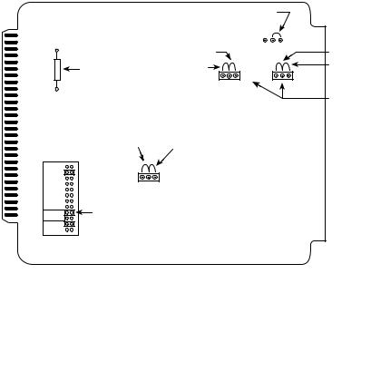
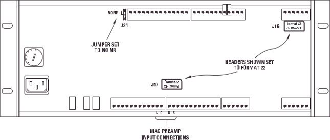
J16, J17 J24 Magnetic format headers: In the standard configuration the CP65 is fitted with two channels of A-type noise reduction and therefore does not provide processing for signals entering through the Mag/Aux inputs on TB3 and TB4. Fitting Cat. No. 300 SR/A modules in place of the normal Cat. No. 350 SR modules provides the two additional channels of A-type noise reduction needed for decoding magnetic sound-tracks from 70mm Dolby Stereo (format 42) prints. Link headers J16 and J17 allow signals from the magnetic inputs to be routed through the noise reduction circuitry; link J24 selects whether the noise reduction decoders are switched on when the Mag/Aux format is selected.
Standard CP65 or CP65A
In a standard CP65 (fitted with one Cat. No. 222 and two Cat. No. 350 SR modules) or a CP65-A (fitted with one Cat. No. 222 only) links J16 and J17 should be fitted so that the words Format 22 appear the right way up. J24 should be fitted in the NO NR position.
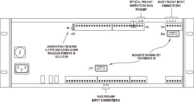
2-9
CP65-300
In a CP65-300 (when Cat. No. 300 modules are fitted in place of the normal Cat. No. 350 modules) J16 and J18 should be rotated so that the words “Format 42” appears the right way up. With J24 in the “NR” position input signals will be A-type decoded when the Mag/Aux format is selected. With J24 in the “NO NR” position signals pass through the noise reduction modules but the processing will be turned off. If both of these processing options are required frequently an external switch may be connected to J24.
NOTE: To play 70mm Dolby Stereo (Format 42) with a CP65-300, the left, center, right, and surround outputs of the magnetic pre-amp must be connected to TB6 and the Le and Re outputs must be connected to TB4. If changing between an optical format and mag format 42 is required, external switching may be added (or J16 must be manually rotated to the Format 22 position for optical playback and to Format 42 for 70mm playback).

2-10
Cat. No. 241 Surround Equalization and Optical Bass Extension. Module (if fitted).
J1
High |
Low |
subwoofer |
subwoofer |
output |
output |
Cat. No. 241
J1 Optical Bass Extension output level: sets the output level range for the subwoofer channel. In the HIGH position J1 is set at the factory for a power amplifier input sensitivity of between 90 mV and 1.23 V. If the power amplifiers used in the installation are very sensitive (10 mV to 100 mV input sensitivity), it may be necessary to set J1 to the LOW position. If you are unsure of the sensitivity of your power amplifiers set J1 to the LOW position initially. If the high output position is required this will be determined during OBE alignment.

2-11
STEP 10 If they are not already installed in the CP65 card cage, install all of the cards for your system as shown.
THESE MODULES ARE
NECESSARY FOR BYPASS
OPERATION
Cat. No. |
Cat. No. |
Cat. No. |
Cat. No. |
Cat. No. |
Cat. No. |
Cat. No. |
|
240A |
240A |
350 SR |
350 SR |
222 |
|
150 |
64 |
(spare) |
optical |
300 SR/A |
300 SR/A |
2-channel |
2:4 ch |
EQ |
|
|
preamp |
450 A |
450 A |
A-type |
|
decoder |
L |
|
|
Lt |
Rt |
Lt/Rt |
|
|
|
|
|
(C) |
(S) |
(L,R) |
|
|
|
|
|
|
|
|
|
L |
|
Proj. 1 |
|
|
|
|
signal |
C |
|
|
|
|
|
present R |
|
||
|
|
|
|
|
|
||
GAIN |
|
|
|
|
|
S |
|
Lt |
|
|
|
|
|
|
|
hf |
|
|
|
Lt |
|
|
|
GAIN |
|
|
|
|
|
|
|
|
|
|
|
|
|
|
|
Rt |
|
|
|
|
|
|
|
hf |
|
|
|
|
|
|
|
Lt tp |
|
|
|
|
|
|
|
Lt |
|
SR |
SR |
|
delay 4 |
|
|
|
|
|
|
|
|||
signal |
|
|
|
|
|
||
present |
|
Dolby |
Dolby |
|
|
|
|
Rt |
|
Rt |
|
|
|
||
|
|
|
|
|
|
||
Rt tp |
|
|
|
|
|
|
|
GAIN |
|
|
|
|
|
|
|
Lt |
|
|
|
|
|
|
|
hf |
|
|
|
Dolby |
|
|
Dolby |
GAIN |
|
|
|
|
|
||
Rt |
|
|
|
|
|
|
|
hf |
|
|
|
|
|
|
|
Proj. 2 |
|
|
|
|
Lt |
tp |
|
|
|
|
|
|
|
|
|
gnd |
|
|
|
|
Rt tp |
|
|
|
|
|
|
|
gnd |
|
|
Cat. No. |
Cat. No. |
64 |
64 |
EQ |
EQ |
C |
R |
|
|
Subwoofer |
|
|
n-sync |
|
|
surr |
|
|
gain |
|
|
Left Surround |
Dolby |
Dolby |
Right Surround |
|
Cat. No. |
Cat. No. |
Cat. No. |
Cat. No. |
|
|
441 |
|
242 |
443 |
249 |
|
surround |
B chain |
control |
voltage |
|
|
and |
|
|
|
regulator |
|
subwoofer |
|
|
|
|
signal |
mono eq |
|
|
||
present |
mono |
|
|
|
|
|
tp |
gain |
L |
|
|
|
on |
non-sync |
|
|
|
|
cut |
|
R |
|
|
|
|
|
|
|
|
auto |
freq |
|
L |
|
|
off |
Q |
|
|
24V |
|
|
C |
power |
|||
|
signal |
||||
opt gain |
supply |
15V |
|||
mag/dig |
present R |
status |
15V |
||
gain |
|
Ls |
|
||
treble |
|
|
|
||
gnd |
|
|
|||
|
cut |
|
|
||
|
|
L |
|
|
|
mid |
freq |
|
|
|
|
|
|
|
|
||
|
Q |
test |
C |
|
|
|
|
|
|
||
|
bass |
points |
R |
|
|
|
tp |
|
Ls |
|
|
treble |
|
|
|
|
|
|
cut |
|
|
|
|
mid |
freq |
|
L |
|
|
|
Q |
gain |
C |
|
bypass |
|
|
R |
|
||
|
bass |
|
|
||
|
|
|
|
||
|
gain |
|
Ls |
|
gain |
|
gnd |
|
|
|
|
signal |
|
|
|
|
|
present |
|
|
|
|
|
Cat. No.
|
259 |
transformer |
|
module |
|
normal |
spare |
fuse |
|
bypass |
spare |
fuse |
|
normal |
bypass |
|
(reset) |
Card Descriptions: |
|
|
Slot |
|
|
No. |
Card |
Function |
1 |
Slot for spare |
Spare location for Cat. No. 240A (or the older |
|
Cat. No. 240A Card |
Cat. No. 240). |
2 |
Cat. No. 240A |
Amplifies the outputs of the solar cell in the |
|
Optical Preamplifier |
selected projector. Electronic switches select |
|
Card |
projector No. 1 or 2. The older Cat. No. 240 may also |
|
|
be used. |
3,4 |
Cat. No. 350 |
Each module contains a single channel |
|
Spectral recording |
of Dolby spectral recording (SR) processing |
|
Modules |
for optical soundtracks recorded with Dolby SR (Format |
|
|
05). |
Note:
1)Some installations may use two Cat. No. 300 SR/A Processing modules in place of Cat. No. 350.
2)In CP65-A, Cat. No. 350/300 are not fitted and the slots are empty.
2-12
Slot |
|
|
No. |
Card |
Function |
5 |
Cat. No. 222 |
Contains two channels of Dolby A-type noise |
|
Two-channel Noise |
reduction circuitry with LED indicators to set |
|
Reduction Module |
Dolby Level. |
6 |
Cat. No. 150 |
Derives left, right, center, and surround |
|
2:4 Channel Decoder |
information from the two optical tracks on the |
|
Card |
film. |
7,8,9 |
Cat. No. 64B |
Contains treble and bass controls and 27 |
|
Equalizer Module |
third-octave equalizer controls. One card is used |
|
|
for each front channel: left, center, right. |
10 |
Cat No. 441 |
(1) Provides equalization for the surround |
|
Surround Equalizer, |
channels. |
|
Subwoofer card. |
(2) Extracts low frequency information from the L, |
|
|
C, and R signals and sends this signal to a |
|
|
subwoofer output through an equalizer and a fader |
|
|
circuit. |
|
|
(3) Provides Subwoofer input for magnetic and |
|
|
digital soundtracks and Stereo Surround from a |
|
|
Dolby Digital adapter. |
|
|
Note: Cat. No. 241 may also be used in this |
|
|
position but does not provide (3) above. |
11 |
Cat. No. 242 |
Contains the signal processing circuitry for the |
|
B-Chain Card |
B-Chain except for the equalizers. Has input buffers |
|
|
and filters for non-sync, aux and magnetic sources, |
|
|
electronic switches to select input sources, a 4- |
|
|
channel fader circuit, and output level |
|
|
potentiometers for L,C,R,S. |
12 |
Cat. No. 443 |
Configures the CP65 for the selected format. |
|
Control Logic Card |
Also contains fader mute and fader local/remote |
|
|
status circuits. Generates control logic signals for |
|
|
other cards in the CP65. Its inputs are the Cat. |
|
|
No. 447 front panel controls, external remote |
|
|
boxes, or automation inputs to the CP65. It also |
|
|
contains a jumper block to enable the wake-up |
|
|
condition to be preselected. |
2-13
Slot |
|
|
No. |
Card |
Function |
13 |
Cat. No. 249 |
Contains a semi-regulated power supply with |
|
Power Supply Module nominal outputs of +15V, -15V, and 24V. Also |
|
|
|
contains the bypass amplifier, gain trimmer, and a |
|
|
+12V bypass power supply. |
14 |
Cat. No. 259 |
Contains two power transformers (main and |
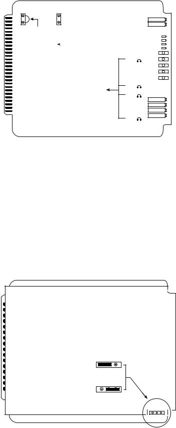
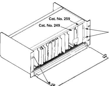
Transformer Module bypass) that convert mains voltage AC to lowvoltage AC. The selector switch for main voltages is accessible through the backplane. It permits a choice of the following nominal mains voltages: 100, 120, 140, 200, 220, and 240V.
As a safety feature in many countries, the Cat. No. 249 module is held in place by a retainer bracket mounted to the Cat. No. 259 module. To withdraw the Cat. No. 249 it is first necessary to remove the Cat. No. 259. Do this by disconnecticng the power cord from the Cat. No. 259 and then removing the two screws indicated by arrows. Remove the Cat. No. 259 followed by the Cat. No. 249.
2-14
ADDITIONAL INFORMATION FOR THE SAFE OPERATION OF THE CP65
To ensure proper operation and guard against potential shock hazard, the CP65 must be connected only to a properly wired, grounded (earthed) mains receptacle. If you are uncertain about the wiring of your mains outlet do not use it. Consult a qualified electrician. The power cord is supplied with either a standard U.S.A. three-prong plug or with unterminated leads for use in other countries. The wires are colored in accordance with the following international code:
|
International |
U.S. |
live or hot |
brown |
black |
neutral |
blue |
white |
earth |
green/yellow |
green/yellow |
Before the power cord is connected to the CP65, ensure that a qualified electrician has wired the cord following the code.
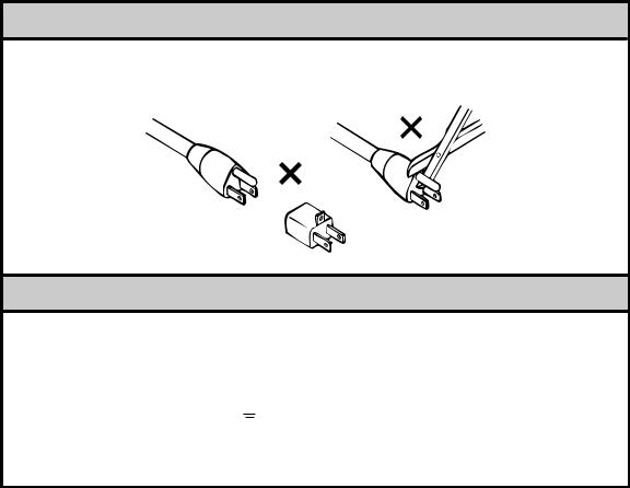
U.S. Style Plugs
The ground terminal of the plug is connected directly to the chassis of the unit. For continued protection against electric shock, a three-pin power receptacle MUST be used, and the ground wire MUST always be connected. DO NOT use a ground-lifting adaptor and NEVER cut the ground pin on a three-prong plug.
Connections for United Kingdom
WARNING: THIS APPARATUS MUST BE EARTHED.
As the colours of the cores in the mains lead may not correspond with the coloured markings identifying the terminals in your plug, proceed as follows:
-the core which is coloured green and yellow must be connected to the terminal in the plug which is marked with the letter E or by the earth symbol  , or coloured green or green and yellow.
-the core which is coloured blue must be connected to the terminal which is marked with the letter N or coloured black.
-the core which is coloured brown must be connected to the terminal which is marked with the letter L or coloured red.
WARNING—Before you connect the unit to mains power, check that it has been set to the correct mains voltage and that the correct fuse is installed. To reduce the risk of fire, replace the fuse only with the same type and 250V rating:
Voltage Setting |
Fuse |
Type |
100/120/140 VAC |
1.25 A |
1/4" x 1-1/4" slow-blow |
200/220/240 VAC |
T 630 mA |
5 x 20mm time lag. |
2-15
IEC NOTICES
IMPORTANT SAFETY NOTICE
This unit complies with the safety standard IEC65. To ensure safe operation and to guard against potential shock hazard or risk of fire, the following must be observed:
•If the unit has a voltage selector, ensure that it is set to the correct mains voltage for your supply. If there is no voltage selector, ensure that your supply is in the correct range for the input requirement of the unit.
•Ensure fuses fitted are the correct rating and type as marked on the unit.
•The unit must be earthed by connecting to a correctly wired and earthed power outlet.
•The power cord supplied with this unit must be wired as follows:
Live—Brown Neutral—Blue Earth—Green/Yellow
IMPORTANT – NOTE DE SECURITE
Ce materiel est conforme à la norme IEC65. Pour vous assurer d'un fonctionnement sans danger et de prévenir tout choc électrique ou tout risque d'incendie, veillez à observer les recommandations suivantes.
•Le selecteur de tension doit être placé sur la valeur correspondante à votre alimentation réseau.
•Les fusibles doivent correspondre à la valeur indiquée sur le materiel.
•Le materiel doit être correctement relié à la terre.
•Le cordon secteur livré avec le materiel doit être cablé de la manière suivante:
Phase—Brun Neutre—Bleu Terre—Vert/Jaune
WICHTIGER SICHERHEITSHINWEIS
Dieses Gerät entspricht der Sicherheitsnorm IEC65. Für das sichere Funktionieren des Gerätes und zur Unfallverhütung (elektrischer Schlag, Feuer) sind die folgenden Regeln unbedingt einzuhalten:
• Der Spannungswähler muß auf Ihre Netzspannung eingestellt sein.
•Die Sicherungen müssen in Type und Stromwert mit den Angaben auf dem Gerät übereinstimmen.
•Die Erdung des Gerätes muß über eine geerdete Steckdose gewährleistet sein.
•Das mitgelieferte Netzkabel muß wie folgt verdrahtet werden:
Phase—braun Nulleiter—blau Erde—grün/gelb
NORME DI SICUREZZA – IMPORTANTE
Questa apparecchiatura è stata costruita in accordo alle norme di sicurezza IEC 65. Per una perfetta sicurezza ed al fine di evitare eventuali rischi di scossa êlettrica o d'incendio vanno osservate le seguenti misure di sicurezza:
•Assicurarsi che il selettore di cambio tensione sia posizionato sul valore corretto.
•Assicurarsi che la portata ed il tipo di fusibili siano quelli prescritti dalla casa costruttrice.
•L'apparecchiatura deve avere un collegamento di messa a terra ben eseguito; anche la connessione rete deve
avere un collegamento a terra. |
|
. |
• Il cavo di alimentazione a corredo dell'apparecchiatura deve essere collegato come segue: |
||
Filo tensione—Marrone |
Neutro—Blu |
Massa—Verde/Giallo |
AVISO IMPORTANTE DE SEGURIDAD
Esta unidad cumple con la norma de seguridad IEC65. Para asegurarse un funcionamiento seguro y prevenir cualquier posible peligro de descarga o riesgo de incendio, se han de observar las siguientes precauciones:
• Asegúrese que el selector de tensión esté ajustado a la tensión correcta para su alimentación.
•Asegúrese que los fusibles colocados son del tipo y valor correctos, tal como se marca en la unidad.
•La unidad debe ser puesta a tierra, conectándola a un conector de red correctamente cableado y puesto a tierra.
•El cable de red suministrado con esta unidad, debe ser cableado como sigue:
Vivo—Marrón Neutro—Azul Tierra—Verde/Amarillo
VIKTIGA SÄKERHETSÅTGÄRDER!
Denna enhet uppfyller säkerhetsstandard IEC65. För att garantera säkerheten och gardera mot eventuell elchock eller brandrisk, måste följande observeras:
•Kontrollera att spänningsväljaren är inställd på korrekt nätspänning.
•Konrollera att säkringarna är av rätt typ och för rätt strömstyrka så som anvisningarna på enheten föreskriver
•Enheten måste vara jordad genom anslutning till ett korrekt kopplat och jordat el-uttag.
•El-sladden som medföljer denna enhet måste kopplas enligt foljande:
Fas—Brun Neutral—Blå Jord—Grön/Gul
BELANGRIJK VEILIGHEIDS-VOORSCHRIFT:
Deze unit voldoet aan de IEC65 veiligheids-standaards. Voor een veilig gebruik en om het gevaar van electrische schokken en het risico van brand te vermijden, dienen de volgende regels in acht te worden genomen:
•Controleer of de spanningscaroussel op het juiste Voltage staat.
•Gebruik alleen zekeringen van de aangegeven typen en waarden.
•Aansluiting van de unit alleen aan een geaarde wandcontactdoos.
•De netkabel die met de unit wordt geleverd, moet als volgt worden aangesloten:
Fase—Bruin Nul—Blauw Aarde—Groen/Geel
GB
F
D
I
E
S
NL
2-16
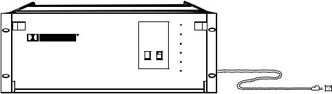
STEP 11 Turn the front pannel FADER fully down, then connect the CP65 to mains power.
Model CP65
STEP 12 With the NORMAL/BYPASS switch (accessible with the front door open) in the NORMAL position, verify that all three LEDs on the Cat. No. 249 Power Supply Module are lit. Close the front door and verify that format 04 Dolby stereo optical with surround, local active, and proj 1 or proj 2 LEDs are on (unless a different wake-up format was selected on the Cat. No. 443).
STEP 13 Select each format in turn, using the buttons on the front panel and check that the associated LED lights.
STEP 14 Press the MUTE pushbutton switch; the LED on the switch should blink. Press the MUTE pushbutton switch again; the LED on the switch should be off.
STEP 15 Set the NORMAL/BYPASS switch to the BYPASS position. The bypass
LED on the front panel should blink and all other LEDs should be off.
STEP 16 Return the NORMAL/BYPASS switch back to the NORMAL position and apply power to the other projection room equipment.
HUM PROBLEMS
If you hear undesirable hum from the speakers when you apply power to the CP65 and other projection room equipment, check the following list for possible causes:
1.Ground loops caused by audio signal wiring, especially to power amplifiers. Only one end of an audio shield wire should be connected. See Pages 2- 3 and 2-4. Be sure to check the booth monitor installation.
The CP65 backplane contains a link which connects frame ground to signal/power ground (TB2 terminals 8 and 9). If you have checked items 1 through 7 and hum is still present, removing this link may fix the problem.
2.Projector power wiring. All mains wiring should be properly grounded.
3.Room lighting dimmer controls (SCR-TYPE).
2-17
4.Power amplifiers. Disconnect from the CP65 and ground the inputs to determine if the power amplifiers are causing hum problems.
With CP65 FADER turned up and format 04 selected:
5.Solar cell wiring. Check the shield connections. Cell wiring should be placed away from mains and other wiring.
6.Exciter lamp power supply. Check for ripple on the DC power supply outputs. Some old exciter lamp power supplies and emergency supplies provide AC to the lamp. The resulting hum makes them totally unsuitable for a stereo playback system. Such exciter supplies should be replaced.
7.Projection room lighting/solar cells. Ambient lighting, especially florescent tubes, can leak into the solar cell area and cause hum.

3-1
SECTION 3
AN OVERVIEW OF THE ALIGNMENT PROCEDURE
This section is an overview of the general principles involved in the alignment of Dolby cinema equipment. It is useful to develop an understanding of why the CP65 is aligned as described in this manual. If the installer is already familiar with these principles, or is in a hurry to complete the installation, this section may be read later. Continue the installation procedure beginning with Section 4.
1. Aligning the A-Chain
The A-Chain is first calibrated by use of the Cat. No. 69 Dolby Tone test film to establish the correct Dolby operating level within the CP65 and to ensure correct tracking of the Dolby noise reduction circuit.
Pink noise is used for equalization of the A-chain. (Pink noise is similar to white noise but provides equal energy per octave of bandwidth.) Pink noise for A-chain alignment is recorded on the other side of the Cat. No. 69 test film. The output should be displayed on a Real Time Analyzer (RTA) so adjustments can be made quickly.
The optical slit is the key element in the A-chain because it imposes the initial limitation on the high-frequency response of the system. Light from the exciter lamp passes through the optical slit and is focussed on the optical soundtracks on the film. The light that passes through the soundtracks falls on the stereo solar cell which generates an electrical signal that is proportional to the audio signal recorded on the optical soundtracks. The slit introduces high frequency loss which must be compensated by circuitry in the Cat. No. 240A optical preamplifier (see Appendix B).
The slit image must be correctly focussed on the film and must be precisely at right angles to the direction of film movement in order to maintain the correct phase relationships between the two optical tracks. Any azimuth error will show as a loss of high frequency in the front channels and potentially excessive crosstalk in the surround channels.
Each channel in the Cat. No. 240A optical preamplifier is equipped with a slit loss equalizer control. Adjustment of this control shifts a fixed amount of boost upward or downward in frequency, but the shape of the curve remains constant. A perfectly flat response up to a minimum of 12 kHz can be achieved possible. See Appendix B for further details.
2. Aligning the B-Chain
In most theatre playback systems, the acoustical qualities of the theatre are difficult to change. Therefore, the primary area where improvement is possible is correcting loudspeaker response errors caused by the theatre acoustic environment.
It is not practical for the entire cinema industry to standardize on a single make and model of loudspeaker. In any event, the different acoustical characteristics of individual theatres would, to some extent, negate any such standardized speakers. Electronic equalization of each loudspeaker system achieves consistent results in a broad spectrum of environments,
3-2
and with a broad range of speakers. Accurate equalization requires the use of standardized acoustic measurement procedures.
A pink noise generator provides a continuous random noise signal that covers the total bandwidth and is used to measure and adjust the response of the loudspeakers. The use of random noise eliminates the problems inherent with tones (standing wave patterns in the theatres) and enables the frequency response of the entire system to be observed. Each channel can be measured and adjusted independently of the other channels.
A calibrated microphone is placed in the auditorium to receive the pink noise reproduced by the loudspeaker; the output of the microphone is fed to a real time analyzer (RTA). The RTA displays the complete audio spectrum received by the microphone in the form of a frequency response curve. Pure pink noise would yield a “flat” horizontal line on the RTA. Thus, the effect of adjustments to the equalizers is quickly and easily seen.
One of the problems inherent in equalization is the nature of the environment. In an open space, a perfect loudspeaker, radiating a perfectly flat response in all directions, placed in front of a perfectly flat microphone, producing perfectly flat response to sounds arriving from all directions, will produce a perfectly flat response on the RTA from pink noise. In an enclosed space such as a theatre, the results are different. When the pink noise generator is first turned on, all of the sound that initially reaches the microphone comes directly from the loudspeaker; the response is flat–for a few milliseconds. Then reflected sound from the walls, ceiling, floor, seats, etc. starts to arrive at the microphone together with the direct sound from the loudspeaker. This indirect or reflected sound reinforces the direct sound. The system soon settles into an equilibrium condition. As much energy is being absorbed at the walls, ceiling, etc. as is fed into the room. Since high and mid frequency energy is absorbed when sound is reflected, the displayed response appears to have a rising bass and a falling treble characteristic. At first glance, rolling off the bass and boosting the high frequencies may appear to be the logical approach for a flat steady-state response, but such an arrangement works only on sustained sounds. Dialogue contains short, impulsive sounds and will yield a much-too-bright result because there is no time for reverberation to build and add to the original sound. What is required is a curve that favors such impulsive “first arrival” sound and implies the same gently falling response that is observed when the output of an ideal loudspeaker is measured with a perfect microphone in the theatre.
The amount of reverberation varies with frequency and the higher the frequency the more the treble will be absorbed rather than being reflected. A typical reverberation curve in a theatre rolls off at about 3 dB per octave above 2 kHz. This characteristic is used to define the standard steady-state response curve for all dubbing theatres in which Dolby stereo films are mixed and for all Dolby stereo-equipped cinemas.
The size of the theatre affects the reverberation time and, therefore, the measurement of frequency response. After alignment to this standard curve, some slight adjustment of high frequency slope may be found necessary for extremely large or small theatres. The treble control on the Cat. No. 64 Equalizer card can be adjusted to reduce the output on the response curve by approximately 1 dB at 8 kHz for very large theatres; an increase of 1 dB at 8 kHz may be in order for a very small theatre. Any such adjustment should be based on an evaluation by ear of actual known films rather than as a rule of thumb.
 Loading...