


430

430 SERIES
BACKGROUND NOISE
SUPPRESSOR SYSTEM
Installation and
Operating Instructions
MAIN

INSTALLATION AND
OPERATING INSTRUCTIONS
FOR
430 SERIES BACKGROUND
NOISE SUPPRESSOR SYSTEM
Dolby Laboratories Incorporated
U.S.A. 100 Potrero Avenue, San Francisco, CA 94103
Tel: 415-558-0200; Fax: 415-863-1373
U.K. Wootton Bassett, Wiltshire, SN4 8QJ, England
Tel: 0793-842100; Fax: 0793-842101; Telex: 44849
WARRANTY INFORMATION: warranty on the product covered by this manual is subject to the limitations and disclaimers set forth in the
warranty disclaimer originally shipped with the product and also printed on the back of the invoice.
Dolby and the double-D are registered trademarks of Dolby Laboratories Licensing Corporation.
©1994 Dolby Laboratories
ISSUE 3
S94/9359/10081
Part No. 91262
MAIN
DOLBY 430
DOLBY 430
D
OLBY
430 B
ACKGROUND
N
OISE
S
UPRESSOR
BACKGROUND NOISE SUPPRESSOR
BACKGROUND NOISE SUPPRESSOR
T
he Dolby 430 Series is a background
noise suppressor system for reducing the
broadband noises such as wind or traffic rum-
ble that often mar location recordings. Many
mixers in film and television postproduction
already rely on Dolby Laboratories’
Cat. No.43, a background noise suppression
unit based on a modified version of Dolby
A-type noise reduction. The 430 Series takes
this concept further by using a modified ver-
sion of Dolby SR’s patented combination of
fixed and sliding bands to give more stable
signal handling and a significantly reduced
chance of audible side effects.
While superior in performance to the
Cat. No.43, the 430 Series uses fewer con-
trols. Low- and high-frequency faders adjust
the amount of noise suppression above and
below dominant mid-frequency signals such
as dialogue. A pull-to-engage control permits
varying the preset operating level for record-
ings at unusually high or low levels (overall
gain of the unit remains fixed).
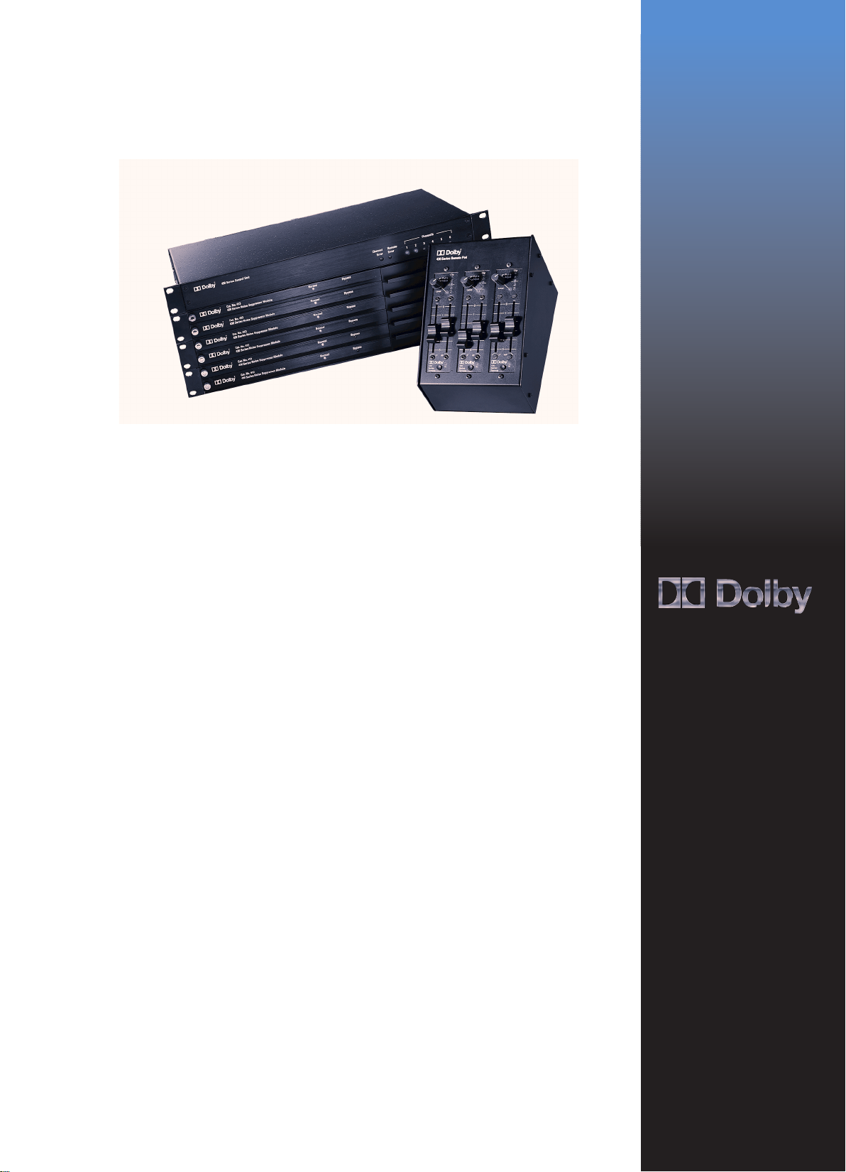
The 430 Series is a modular system pro-
viding from one to six channels of background
noise suppression. A single control unit pro-
vides power and control signals for up to three
single-rackspace frames, each with one or two
channels of processing. All operating controls
are mounted in a remote control module
which may be located up to 15 meters (50
feet) from the control unit. These remote con-
trols have been specifically designed for easy
console mounting. Alternatively, a housing is
available to allow for standalone operation.
100 Potrero Avenue
San Francisco, CA 94103-4813
Telephone 415-558-0200
Fax 415-863-1373
info@dolby.com
Wootton Bassett
Wiltshire SN4 8QJ, England
Telephone (44) 1793-842100
Fax (44) 1793-842101
info@dolby.co.uk
www.dolby.com
MAIN

Signal Processing
Independent low- and high-frequency stages with
maximum noise suppression of approximately
16 and 18 dB, respectively
Signal Connection
3-pin XLR connectors for audio; 34-way ribbon
connector links processing module frames to power
supply/control unit; one 15-way D-connector con-
nects remote controls for all channels
Operating Controls
Operating controls for each channel of processing
are mounted on Cat. No.429 Remote Control
module
Level: rotary control varies signal level in processing
circuitry over a ±6 dB range without changing
overall gain of unit
In/out: push-button with LED indicator switches
processing in and out of circuit
HF & LF: fader controls set attenuation of
unwanted low-level signals
Signal Levels
Nominal input and output level +4 dBr
1
Input Circuits
Electronically balanced, 20 kΩ input impedance,
substantially resistive; common mode rejection
better than 55 dB, 50 Hz to 10 kHz; maximum
input level +27 dBr balanced, +21 dBr unbalanced
Output Circuits
Electronically balanced, approximately 20Ω
output impedance; output balance better than 1 dB
into a symmetrical 600Ω load; output float
2
better than –40 dB, 50 Hz to 1 kHz; maximum
signal level into 600Ω or greater: +26 dBr balanced,
+20 dBr unbalanced; either leg of the output can be
grounded for unbalanced operation with no change
in level
Frequency Response
±1 dB 20 Hz to 20 kHz with LF and HF controls
set to 0
Crosstalk
Channel to channel within a single frame: better than
–94 dB 20 Hz to 20 kHz
Power Line Input
User-selected voltage ranges (50–60 Hz, single-
phase); nominally 100 V (85–110 V), 110 V
(102–132 V), 220 V (187–242 V),
240 V (204–264 V)
Size
Processor and power supply/control units: 44 × 483
mm (standard 1.75 × 19 inches rack mounting );
maximum projection behind mounting surface:
330 mm (13 inches) including connectors; remote
control panels: 150 mm x 39.5 mm (5.91 × 1.56
inches ); maximum projection behind control
surface: 100 mm (3.94 inches) including connec-
tors; may be console-mounted, mounting holes on
142.9 mm (5.63 inches) centers.
Weight
Model Weights (including remotes): 430-S1, 8 kg
(17.5 lb); 430-S2, 9 kg (19.6 lb); 430-S3,12.9 kg
(28.3 lb); 430-S4, 14 kg (30.6 lb); 430-S5,
17.8 kg (39.2 lb); 430-S6, 18.8 kg (41.4 lb)
Accessories
430SU1: single-channel upgrade package with
one channel module, one remote control and rack
mounting frame with blanking plate.
430SU2: two-channel upgrade package with two
channel modules, two remote controls and rack
mounting frame.
430SK1: single-channel upgrade package with one
processing module and one remote control only (no
frame included).
Cat. No. 428: remote housing for up to three
Cat. No. 429 remote controls.
Regulatory Notices
US: This unit is UL listed.
Europe: The 230 Volt unit complies with the
requirements of Low Voltage Directive 73/23/EEC.
Warranty
One-year limited, parts and labor
1
0 dBr = 0.775 mV
2
Output float is the level across a balanced load relative to an interfering
signal injected at one end of the load
Specifications subject to change without notice.
Dolby and the double-D symbol are trademarks of Dolby Laboratories.
© 2000 Dolby Laboratories, Inc.S00/00000
430 S
PECIFICATIONS
DISCLAIMER OF WARRANTIES:
Equipment manufactured by Dolby
Laboratories is warranted against
defects in materials and workmanship
for a period of one year from the date of
purchase. There are no other express
or implied warranties and no warranty
of merchantability or fitness for a partic-
ular purpose.
LIMITATION OF LIABILITY: It is
understood and agreed that Dolby
Laboratories’ liability whether in con-
tract, in tort,under any warranty, in neg-
ligence or otherwise shall not exceed the
cost of repair or replacement of the
defective components and under no cir-
cumstances shall Dolby Laboratories be
liable for incidental, special,direct, indi-
rect or consequential damages (includ-
ing but not limited to damage to soft-
ware or recorded audio or visual mater-
ial), or loss of use,revenue or profit even
if Dolby Laboratories or its agents have
been advised, orally or in writing, of the
possibility of such damages.
DOLBY NOISE REDUCTION
Dolby noise reduction is a family of
signal processes that reduce the noise
inherent in analog recording media,
without affecting the sound being
recorded. While they differ in perfor-
mance and details of operation, all
Dolby NR systems are complementary
processes that first encode the music
when it is recorded, then decode it
when it is played back. They also treat
soft signals separately from loud ones,
and vary the NR action with frequency
to avoid the side effects typical of other
systems.
Dolby A-type noise reduction, intro-
duced in 1965, was originally intended
for use by professional recording studios
to make quieter master tape recordings.
In the early 1970s its use was extended
to film studios and motion picture
release prints to make films sound
better.
Dolby SR (spectral recording), intro-
duced in 1986, was designed not only to
provide more noise reduction than
A-type, but also to enable analog master
recordings that equal or surpass 16-bit
digital recordings with respect to overall
dynamic range. Today, analog with
Dolby SR is still a preferred format for
some musicians, producers, and record-
ing and mastering facilities, and is the
standard format for the analog sound-
tracks of virtually all feature films.
MAIN

i
TABLE OF CONTENTS
INTRODUCTION
SECTION 1 UNIT CONFIGURATIONS
1.1 The Model 430 System .................................................................................................. 1-1
1.2 Accessories .................................................................................................................... 1-1
SECTION 2 OPERATION
2.1 Controls .......................................................................................................................... 2-1
2.2 Practical Operation ......................................................................................................... 2-2
2.3 Console Signal Path Insertion Guide ............................................................................. 2-3
SECTION 3 INSTALLATION
3.1 Control unit and Suppressor Frames ............................................................................. 3-1
3.2 Console Mounting of Remotes ....................................................................................... 3-3
3.3 Channel Number Assignment ........................................................................................ 3-3
3.4 Panel Cut-Out Templates for Cat. No. 428 Remotes ..................................................... 3-4
3.5 Regulatory Notices ......................................................................................................... 3-5
SECTION 4 THEORY OF OPERATION
SECTION 5 SCHEMATIC DIAGRAMS
APPENDIX
A1 Plugging Precautions ..................................................................................................... A-1
MAIN

ii
INTRODUCTION
The Model 430 Series is a playback-only noise reduction system intended primarily to reduce unwanted
ambient noise from location recordings. Typically, this noise is generated by broadband sources such as
generators, wind, or traffic.
The Model 430 Series is a second-generation design, following from the Cat. No. 43 unit—a successful
background noise suppressor in widespread use in post-production facilities throughout the world. The
Model 430 unit offers several benefits over the earlier design, including improved ease of operation, and a
reduced risk of side effects.
The earlier design was based on Dolby A-type noise reduction techniques, and incorporated user control of
each of its four fixed bands to accomplish playback noise reduction. The Model 430 design is based on
Dolby spectral recording techniques, with a multiple combination of low- and high-frequency fixed and
sliding bands. Basic user controls have been reduced to two, controlling the amount of playback noise
reduction above and below the dominant signal of interest, typically above and below mid-frequency dialog
components. The use of Dolby SR fixed and sliding bands in combination results in much more stable
signal handling with a significantly reduced chance of audible background signal pumping. Nevertheless,
the user is cautioned that, as with all non-complementary playback-only noise reduction devices, excessive
use and certain signal combinations can lead to audible side-effects.
The Model 430 Series is not intended for suppression of spot-tone signals, such as camera noise or power
line hum interference. Noise sources such as this may well be better treated with a dip filter.
In typical applications, the Model 430 Series unit is placed in the signal path of a sound mixing console
where nominal line levels are present. It is intended to operate at a level around +4 dBr (Ref: 0.775 Vrms).
MAIN
1-1
SECTION 1
UNIT CONFIGURATIONS
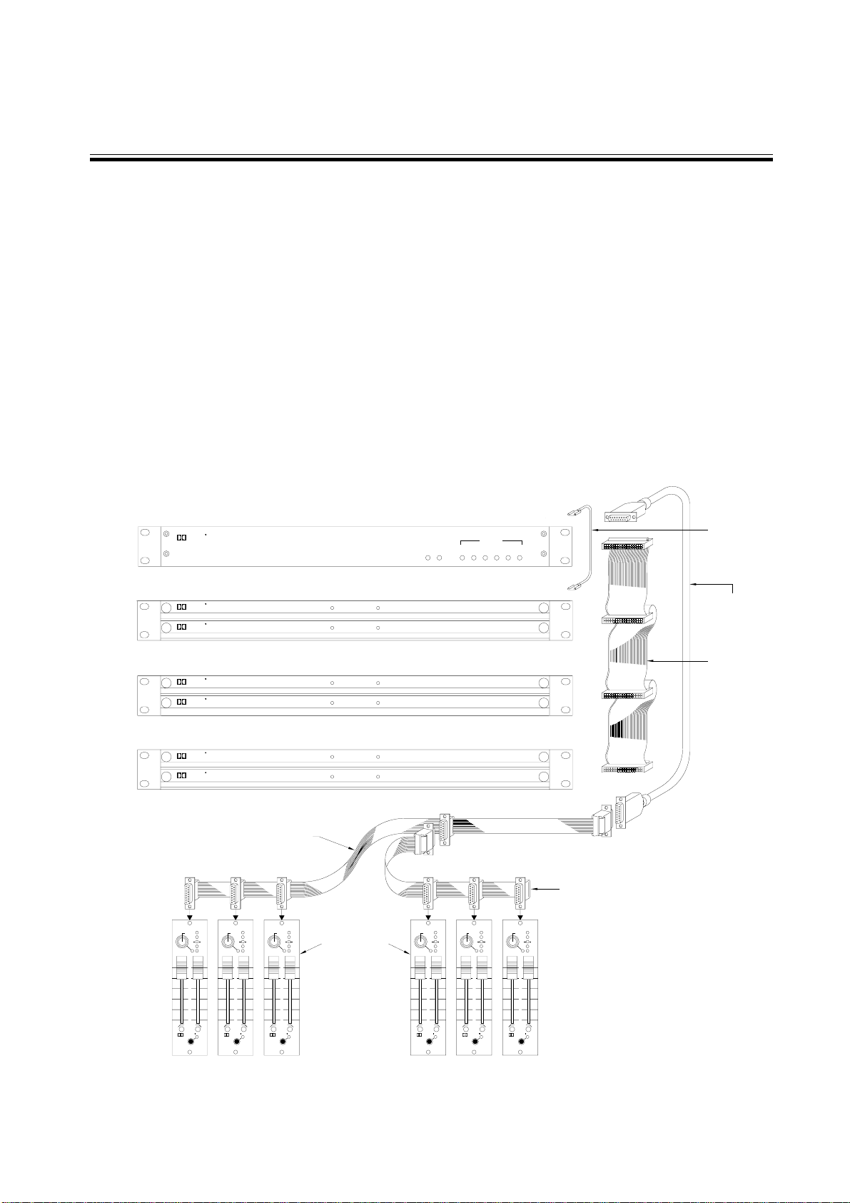
1.1 The Model 430 System
The Model 430 is a modular system which has a control unit containing the power supply and
microprocessor. The control unit links to one or more enclosures each of which contains one or two noise
suppression modules and also links to one or more remote control modules. The 40mm wide format of the
remote control modules makes them easily mountable in spare sections of many mixing consoles.
Alternatively, they may be mounted in an optional housing which can mount up to three remote control
modules.
Linking of the units is accomplished by a short ribbon cable bus between the control unit and the suppressor
module enclosures and a 15-meter shielded cable between the control unit and remote control modules.
Where the remotes are console mounted, there are 15-way ribbon cable assemblies which allow flexible
use of the spare space in the console.
The figure below shows a complete 6-channel system along with the various component part numbers.
A1F4356B REV2
430 Series Noise Suppressor Module
Cat. No. 413
Dolby
Normal
Bypass
5
0
1
2
3
4
Dolby
430
Series
Remote
Level
Pull to
Clip
Adjust
LF
HF
in
Bypass
Normal
Dolby
Cat. No. 413
430 Series Noise Suppressor Module
430 Series Control Unit
6
5
4
3
2
1
Channels
Error
Remote
Error
Channel
Dolby
430 Series Noise Suppressor Module
Cat. No. 413
Dolby
Normal
Bypass
Bypass
Normal
Dolby
Cat. No. 413
430 Series Noise Suppressor Module
430 Series Noise Suppressor Module
Cat. No. 413
Dolby
Normal
Bypass
Bypass
Normal
Dolby
Cat. No. 413
430 Series Noise Suppressor Module
in
HF
LF
Adjust
Clip
Pull to
Level
Remote
Series
430
Dolby
4
3
2
1
0
5
in
HF
LF
Adjust
Clip
Pull to
Level
Remote
Series
430
Dolby
4
3
2
1
0
5
in
HF
LF
Adjust
Clip
Pull to
Level
Remote
Series
430
Dolby
4
3
2
1
0
5
in
HF
LF
Adjust
Clip
Pull to
Level
Remote
Series
430
Dolby
4
3
2
1
0
5
in
HF
LF
Adjust
Clip
Pull to
Level
Remote
Series
430
Dolby
4
3
2
1
0
5
430PS POWER SUPPLY AND CONTROL UNIT
430SU2 2 CHANNEL SUPPRESSOR UNIT
430SU2 2 CHANNEL SUPPRESSOR UNIT
430SU2 2 CHANNEL SUPPRESSOR UNIT
PART NO. 83093
PART NO. 83128
430 SERIES
430 SERIES
6 CHANNEL
15 METER
REMOTE CABLE
FLAT CABLE
PART NO. 83131
PART NO.83127
430 SERIES
3 REMOTES CABLE
REMOTE CONTROLS
CAT. NO. 429
430 SERIES
REMOTE EXTENSION CABLE
(ALSO USED FOR 4 REMOTES)
430 SERIES
PART NO. 83121
LINK
CHASSIS GROUND
MAIN
 Loading...