


 Loading...
Service Manual
Model Number
DS7420
DS7425DLX
UL Part Number 6900470759 6900471604
IMPORTANT SAFETY INFORMATION: Always read this manual first before attempting to service this stove. For your safety, always comply with all warnings and safety instructions contained in this manual to prevent personal injury or property damage.
Dimplex North America Limited
1367 Industrial Road  Cambridge ON Canada N1R 7G8
1-888-346-7539  www.dimplex.com
In keeping with our policy of continuous product development, we reserve the right to make changes without notice.
© 2011 Dimplex North America Limited
REV PCN DATE
00 - 31-AUG-11
7400480000R00

TABLE OF CONTENTS
OPERATION. . . . . . . . . . . . . . . . . . . . . . . . . . . . . 3 OPERATION - DS7420 MOD A - D. . . . . . . . . . . . . . . . . . . . . 4 Maintenance . . . . . . . . . . . . . . . . . . . . . . . . . . . . 5 Exploded Parts Diagram . . . . . . . . . . . . . . . . . . . . . . 6
Wiring Diagram. . . . . . . . . . . . . . . . . . . . . . . . . . |
|
. 7 |
TO REPLACE UPPER LIGHT BULB . . . . . . . . . . . . . . . . . . . |
|
. 8 |
TO REPLACE LOWER LIGHT BULBS. . . . . . . . . . . . . . . . . . |
. |
8 |
TO REPLACE MAIN Power SWITCH . . . . . . . . . . . . . . . . . . |
|
. 8 |
TO REPLACE UPPER LIGHT ON/OFF SWITCH. . . . . . . . . . . . . . |
. |
8 |
TO REPLACE FLAME MOTOR/FLAME ROD . . . . . . . . . . . . . . . |
. |
9 |
TO REPLACE HEATER ON/OFF SWITCH. . . . . . . . . . . . . . . . . |
|
. 9 |
TO REPLACE HEATER THERMOSTAT CONTROL. . . . . . . . . . . . . |
. |
9 |
TO REPLACE HEATER ASSEMBLY. . . . . . . . . . . . . . . . . . . |
. |
9 |
TO REPLACE THE POWER CORD. . . . . . . . . . . . . . . . . . . |
. 10 |
|
To Replace Remote Control Receiver BOARD. . . . . . . . . . . |
|
10 |
To Replace Log Set Driver BOARD - DS7425DLX Model Only. . . . . 10 |
||
Troubleshooting Guide. . . . . . . . . . . . . . . . . . . . . |
. 11 |
|
Always use a qualified technician or service agency to repair this stove.
! NOTE: Procedures and techniques that are considered important enough to emphasize.
 CAUTION: Procedures and techniques which, if not carefully followed, will result in damage to the equipment.
 Warning: Procedures and techniques which, if not carefully followed, will expose the user to the risk of fire, serious injury, or death.
2 |
www.dimplex.com |
OPERATION
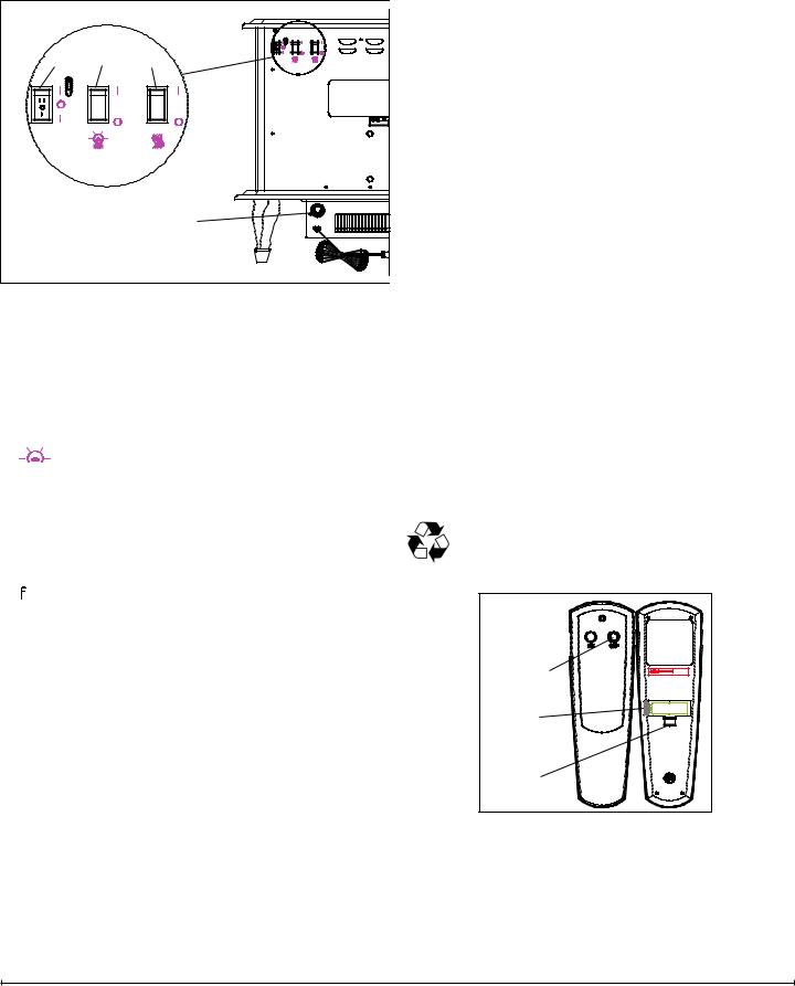
To access the controls, go to the back of the stove (Figure 1).
Figure 1 |
|
|
A |
B |
C |
|
|
D |
A. Three Position On/Off Switch
The switch has two On positions marked with “I” and “II”. The “I” position is for manual operation. In this position the built-in remote control is bypassed.
The “II” position is for operating the unit with the provided remote control. When in “II” position the unit is operated with the ON and OFF buttons of the remote control.
When the switch is in the center position “O” the unit is off.
B. 

 Light On/Off Switch
The Light On/Off Switch supplies power to the upper light of the log bed display area.
C. 
 Heater On/Off Switch
The Heater On/Off Switch supplies power to the heater.
D.  Heater Thermostat Control
To adjust the temperature to your individual requirements, turn the thermostat control clockwise all the way to
turn on the heater. When the room reaches the desired temperature, turn the thermostat knob counter clockwise until you hear a click. Leave in this position to maintain the room temperature at this setting. For additional heat, turn clockwise until you hear the click again and the heater will turn on.
Resetting the Temperature Cutoff Switch
Should the heater overheat, an automatic cut out will turn the heater off and it will not come back on without being reset. It can be reset by switching the Three Position Switch to Off “O” and waiting five (5) minutes before switching the unit back on.
 CAUTION: If you need to continuously reset the heater, unplug the unit and call Customer Service at 1-888-346-7539.
Remote Control
The stove is supplied with an integrated On/Off remote control.
!NOTE: Ensure that the stove’s Three Position Switch is set to the remote Control setting (“II” position).
To operate, push the ON button to turn stove on, push the OFF button to turn the stove off.
Remote Initialization
Follow these steps for remote control initialization and if required, re-initialization:
1.Disconnect power to stove.
2.Set the Three Position On/Off Switch to the Remote position (Figure 1A).
3.Wait a minimum of five (5) seconds and then re-acquire power to stove.
4.Within 10 seconds of re-acquiring power, press the ON button located on the remote control transmitter.
!NOTE: You will have only 10 seconds to perform this last step. Failure to do so will result in these steps needing to be followed again.
Battery Installation
To install or replace the battery:
1.Slide battery cover open on the hand held transmitter (Figure 2).
2.Correctly install one (1) 12 Volt (A23) battery in the battery holder.
3.Close the battery cover.
Battery must be recycled or disposed ofproperly. Check with your Local Authority or Retailer for recycling advice in your area.
Figure 2
On
Button 

Off Button
Plastic
Strip
Battery
Cover
3
OPERATION - DS7420 MOD A - D |
REMOTE CONTROL |
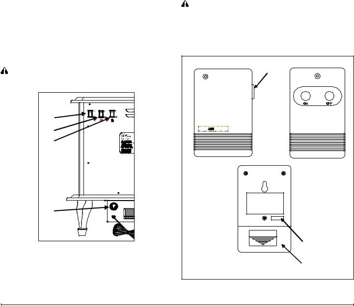
To access the controls, go to the back of the stove. (Figure 3)
A. MAIN POWER ON/OFF SWITCH
The main power on/off switch supplies power to all stove functions (heater & flame).
B. TOP LIGHT ON/OFF SWITCH
The remote control has a range of approximately 50ft. (15.25m) it does not have to be pointed at the stove and can pass through most obstacles (including walls). It is supplied with one of 243 independent frequencies to prevent interference with other units. The frequency designation is indicated on the back of the transmitter (Figure 4)
REMOTE CONTROL INSTALLATION
Controls the light intensity of the log bed display area. |
1. Plug stove cordset into the outlet located on the side of |
|||
C. HEATER ON/OFF SWITCH |
|
the receiver. (Figure 4) |
||
2. |
Plug receiver into the wall outlet. |
|||
The heater on off switch supplies power to the heater. |
||||
3. |
Install a 9 volt battery into the transmitter. (Figure 4) |
|||
D. HEATER THERMOSTAT CONTROL |
||||
! |
NOTE: |
|
||
To adjust the temperature to your individual requirements, |
|
|||
turn the thermostat control clockwise all the way to turn |
• Stove MAIN on/off switch must be in the ON position |
|||
on the heater. When the room reaches the desired tem- |
|
prior to using the Remote Control. |
||
perature, turn the thermostat knob counter clockwise until |
• ON/OFF Remote Control may be used to control most |
|||
you hear a click. Leave in this position to maintain the |
|
other electrical devices including T.V.’s, stereos and |
||
room temperature at this setting. For additional heat, turn |
|
lamps. |
|
|
clockwise until you hear the click again and the heater will |
|
CAUTION: |
|
|
turn on. |
|
|
||
• For indoor use in dry areas only |
||||
RESETTING THE TEMPERATURE CUTOFF SWITCH |
||||
• For use on electrical devices with 15 amp resistive load |
||||
Should the heater overheat, an automatic cut out will turn |
||||
|
or 1/3 HP inductive load |
|||
the heater off and it will not come back on without be- |
|
|||
• 120 volt AC only |
|
|||
ing reset. It can be reset by switching the MAIN ON/OFF |
|
|||
|
|
|
||
SWITCH to OFF and waiting 5 minutes before switching |
|
|
|
|
the unit back on. |
Figure 4 |
Receiver |
||
CAUTION: If you need to continuously reset the heater, |
|
|
|
|
unplug the unit and call Dimplex North America Limited |
|
|
|
|
at 1-800-668-6663. |
|
|
|
|
Figure 3 |
|
|
|
|
A |
|
|
|
|
B |
|
|
|
|
C |
|
|
|
|
D |
|
|
|
|
|
|
|
OPEN |
|
|
|
|
Frequency |
|
|
|
|
Code |
|
|
|
|
Battery |
|
|
|
|
Cover |
|
4 |
|
|
www.dimplex.com |
|
Loading...