


User’s Guide
IMPORTANT SAFETY INFORMATION
The symbols shown above are internationally accepted symbols that warn of potential hazards with electrical products. The lightning flash with arrow point in an equilateral triangle means that there are dangerous voltages present within the unit. The exclamation point in an equilateral triangle indicates that it is necessary for the user to refer to the owner’s manual.
These symbols warn that there are no user serviceable parts inside the unit. Do not open the unit. Do not attempt to service the unit yourself. Refer all servicing to qualified personnel. Opening the chassis for any reason will void the manufacturer’s warranty. Do not get the unit wet. If liquid is spilled on the unit, shut it off immediately and take it to a dealer for service. Disconnect the unit during storms to prevent damage.
SAFETY INSTRUCTIONS
NOTICE FOR CUSTOMERS IF YOUR UNIT IS EQUIPPED WITH A POWER CORD.
WARNING: THIS APPLIANCE MUST BE EARTHED.
The cores in the mains lead are colored in accordance with the following code:
GREEN and YELLOW - Earth BLUE - Neutral |
BROWN - Live |
As colors of the cores in the mains lead of this appliance may not correspond with the colored markings identifying the terminals in your plug, proceed as follows:
•The core which is colored green and yellow must be connected to the terminal in the plug marked with the letter E, or with the earth symbol, or colored green, or green and yellow.
•The core which is colored blue must be connected to the terminal marked N or colored black.
•The core which is colored brown must be connected to the terminal marked L or colored red.
This equipment may require the use of a different line cord, attachment plug, or both, depending on the available power source at installation. If the attachment plug needs to be changed, refer servicing to qualified service personnel who should refer to the table below. The green/yellow wire shall be connected directly to the units chassis.
CONDUCTOR |
WIRE COLOR |
||
|
|
Normal |
Alt |
L |
LIVE |
BROWN |
BLACK |
N |
NEUTRAL |
BLUE |
WHITE |
E |
EARTH GND |
GREEN/YEL |
GREEN |
WARNING: If the ground is defeated, certain fault conditions in the unit or in the system to which it is connected can result in full line voltage between chassis and earth ground. Severe injury or death can then result if the chassis and earth ground are touched simultaneously.
LITHIUM BATTERY WARNING
CAUTION!
This product may contain a lithium battery.There is danger of explosion if the battery is incorrectly replaced. Replace only with an Eveready CR 2032 or equivalent. Make sure the battery is installed with the correct polarity. Discard used batteries according to manufacturer’s instructions.
ADVARSEL!
Lithiumbatteri - Eksplosjonsfare.Ved utskifting benyttes kun batteri som anbefalt av apparatfabrikanten. Brukt batteri returneres apparatleverandøren.
ADVARSEL!
Lithiumbatteri - Eksplosionsfare ved fejlagtig håndtering. Udskiftning må kun ske med batteri av samme fabrikat og type. Levér det brugte batteri tilbage til leverandøren.
VAROITUS!
Paristo voi räjähtää, jos se on virheellisesti asennettu. Vaihda paristo ainoastaan laitevalmistajan suosittelemaan tyyppin. Hävitä käytetty paristo valmistajan ohjeiden mukaisesti.
VARNING!
Explosionsfara vid felaktigt batteribyte. Använd samma batterityp eller en ekvivalent typ som rekommenderas av apparattillverkaren. Kassera använt batteri enligt fabrikantens instruktion.
ELECTROMAGNETIC
COMPATIBILITY
This unit conforms to the Product Specifications noted on the Declaration of Conformity. Operation is subject to the following two conditions:
•this device may not cause harmful interference, and
•this device must accept any interference received, including interference that may cause undesirable operation.
Operation of this unit within significant ectromagnetic fields should be avoided.
• use only shielded interconnecting cables.
IMPORTANT SAFETY INFORMATION
WARNING FOR YOUR PROTECTION
PLEASE READ THE FOLLOWING:
KEEP THESE INSTRUCTIONS
HEED ALL WARNINGS
FOLLOW ALL INSTRUCTIONS
DO NOT USE THIS APPARATUS NEAR WATER
CLEAN ONLY WITH A DRY CLOTH.
DO NOT BLOCK ANY OF THE VENTILATION OPENINGS. INSTALL IN ACCORDANCE WITH THE MANUFACTURER’S INSTRUCTIONS.
DO NOT INSTALL NEAR ANY HEAT SOURCES SUCH AS RADIATORS, HEAT REGISTERS, STOVES, OR OTHER APPARATUS (INCLUDING AMPLIFIERS) THAT PRODUCE HEAT.
ONLY USE ATTACHMENTS/ACCESSORIES SPECIFIED BY THE MANUFACTURER.
UNPLUG THIS APPARATUS DURING LIGHTNING STORMS OR WHEN UNUSED FOR LONG PERIODS OF TIME.
Do not defeat the safety purpose of the polarized or grounding-type plug. A polarized plug has two blades with one wider than the other. A grounding type plug has two blades and a third grounding prong. The wide blade or third prong are provided for your safety. If the provided plug does not fit your outlet, consult an electrician for replacement of the obsolete outlet.
Protect the power cord from being walked on or pinched particularly at plugs, convenience receptacles, and the point where they exit from the apparatus.
Use only with the cart stand, tripod bracket, or table specified by the manufacture, or sold with the apparatus. When a cart is used, use caution when moving the cart/apparatus combination to avoid injury from tip-over.
Refer all servicing to qualified service personnel. Servicing is required when the apparatus has been damaged in any way, such as power-sup- ply cord or plug is damaged, liquid has been spilled or objects have fallen into the apparatus, the apparatus has been exposed to rain or moisture, does not operate normally, or has been dropped.
POWER ON/OFF SWITCH: For products provided with a power switch, the power switch DOES NOT break the connection from the mains.
MAINS DISCONNECT: The plug shall remain readily operable. For rack-mount or installation where plug is not accessible, an all-pole mains switch with a contact separation of at least 3 mm in each pole shall be incorporated into the electrical installation of the rack or building.
FOR UNITS EQUIPPED WITH EXTERNALLY ACCESSIBLE FUSE RECEPTACLE: Replace fuse with same type and rating only.
MULTIPLE-INPUT VOLTAGE:This equipment may require the use of a different line cord, attachment plug, or both, depending on the available power source at installation. Connect this equipment only to the power source indicated on the equipment rear panel. To reduce the risk of fire or electric shock, refer servicing to qualified service personnel or equivalent.
U.K. MAINS PLUG WARNING
A molded mains plug that has been cut off from the cord is unsafe. Discard the mains plug at a suitable disposal facility. NEVER UNDER ANY CIRCUMSTANCES SHOULD YOU INSERT A DAMAGED OR CUT MAINS PLUG INTO A 13 AMP POWER SOCKET. Do not use the mains plug without the fuse cover in place. Replacement fuse covers can be obtained from your local retailer. Replacement fuses are 13 amps and MUST be ASTA approved to BS1362.
DECLARATION OF CONFORMITY
Manufacturer’s Name: |
DigiTech |
Manufacturer’s Address: |
8760 S. Sandy Parkway |
|
Sandy, Utah 84070, USA |
Declares that the product:
Product name: |
Vx400 |
Product option: |
all (requires Class II power adapter that conforms to |
|
the requirements of EN60065, EN60742, or |
|
equivalent.) |
Conforms to the following Product Specifications: |
|
Safety: |
IEC 60065 (1998) |
EMC: |
EN 55013 (1990) |
|
EN 55020 (1991) |
Supplementary Information:
The product herewith complies with the requirements of the Low Voltage Directive 73/23/EEC and the EMC Directive 89/336/EEC as amended by Directive 93/68/EEC.
Vice-President of Engineering
8760 S. Sandy Parkway
Sandy, Utah 84070, USA
Date: May 23, 2003
European Contact: Your local DigiTech Sales and Service Office or
Harman Music Group
8760 South Sandy Parkway
Sandy, Utah
84070 USA
Ph: (801) 566-8800
Fax: (801) 568-7583
Warranty
We at DigiTech are very proud of our products and back-up each one we sell with the following warranty:
1.The warranty registration card must be mailed within ten days after purchase date to validate this warranty.
2.DigiTech warrants this product, when used solely within the U.S., to be free from defects in materials and workmanship under normal use and service.
3.DigiTech liability under this warranty is limited to repairing or replacing defective materials that show evidence of defect, provided the product is returned to DigiTech WITH RETURN AUTHORIZATION, where all parts and labor will be covered up to a period of one year. A Return Authorization number may be obtained from DigiTech by telephone.The company shall not be liable for any consequential damage as a result of the product's use in any circuit or assembly.
4.Proof-of-purchase is considered to be the burden of the consumer.
5.DigiTech reserves the right to make changes in design, or make additions to, or improvements upon this product without incurring any obligation to install the same on products previously manufactured.
6.The consumer forfeits the benefits of this warranty if the product's main assembly is opened and tampered with by anyone other than a certified DigiTech technician or, if the product is used with AC voltages outside of the range suggested by the manufacturer.
7.The foregoing is in lieu of all other warranties, expressed or implied, and DigiTech neither assumes nor authorizes any person to assume any obligation or liability in connection with the sale of this product. In no event shall DigiTech or its dealers be liable for special or consequential damages or from any delay in the performance of this warranty due to causes beyond their control.
NOTE:The information contained in this manual is subject to change at any time without notification. Some information contained in this manual may also be inaccurate due to undocumented changes in the product or operating system since this version of the manual was completed.The information contained in this version of the owner's manual supersedes all previous versions.
Introduction . . . . . . . . . . . . . . . . . . . . . . . . . . . |
.1 |
Included Items . . . . . . . . . . . . . . . . . . . . . . . . . . . . . |
1 |
The Front Panel . . . . . . . . . . . . . . . . . . . . . . . . . . . |
1 |
Rear Panel . . . . . . . . . . . . . . . . . . . . . . . . . . . . . . . . |
2 |
Making Connections . . . . . . . . . . . . . . . . . . . . . . . . |
4 |
PA Rig . . . . . . . . . . . . . . . . . . . . . . . . . . . . . . . . . |
4 |
Recording Setup . . . . . . . . . . . . . . . . . . . . . . . . . . |
4 |
Applying Power . . . . . . . . . . . . . . . . . . . . . . . . . |
5 |
The Presets . . . . . . . . . . . . . . . . . . . . . . . . . . . . . . . |
6 |
Performance . . . . . . . . . . . . . . . . . . . . . . . . . . . . . . |
6 |
Bypass . . . . . . . . . . . . . . . . . . . . . . . . . . . . . . . . . . . |
6 |
Tuner . . . . . . . . . . . . . . . . . . . . . . . . . . . . . . . . . . . |
6 |
CD/Monitor In . . . . . . . . . . . . . . . . . . . . . . . . . . . . |
7 |
Drum Machine . . . . . . . . . . . . . . . . . . . . . . . . . . . . |
7 |
Mic Input and Level . . . . . . . . . . . . . . . . . . . . . . . . . |
7 |
Creating Presets . . . . . . . . . . . . . . . . . . . . . . . . |
8 |
Editing/Creating Presets . . . . . . . . . . . . . . . . . . . . . |
8 |
The Matrix . . . . . . . . . . . . . . . . . . . . . . . . . . . . . . . |
8 |
Storing/Copying/Naming a Preset . . . . . . . . . . . . . . |
8 |
About the Effects . . . . . . . . . . . . . . . . . . . . . . . . . . |
10 |
Mic Modeling . . . . . . . . . . . . . . . . . . . . . . . . . . . . |
10 |
Compressor/Noise Gate . . . . . . . . . . . . . . . . . . . |
11 |
Mic Pre/ Voice . . . . . . . . . . . . . . . . . . . . . . . . . . . |
11 |
EQ . . . . . . . . . . . . . . . . . . . . . . . . . . . . . . . . . . . . |
12 |
Mod Effects . . . . . . . . . . . . . . . . . . . . . . . . . . . . . |
12 |
Chorus . . . . . . . . . . . . . . . . . . . . . . . . . . . . . . . |
12 |
Flanger . . . . . . . . . . . . . . . . . . . . . . . . . . . . . . . |
12 |
Phaser . . . . . . . . . . . . . . . . . . . . . . . . . . . . . . . . |
13 |
Tremolo . . . . . . . . . . . . . . . . . . . . . . . . . . . . . . |
13 |
Vibrato . . . . . . . . . . . . . . . . . . . . . . . . . . . . . . . |
13 |
Strobe . . . . . . . . . . . . . . . . . . . . . . . . . . . . . . . . |
13 |
Doubler . . . . . . . . . . . . . . . . . . . . . . . . . . . . . . . |
13 |
Envelope . . . . . . . . . . . . . . . . . . . . . . . . . . . . . . |
14 |
Pixelator . . . . . . . . . . . . . . . . . . . . . . . . . . . . . . |
14 |
Detune . . . . . . . . . . . . . . . . . . . . . . . . . . . . . . . |
14 |
Pitch . . . . . . . . . . . . . . . . . . . . . . . . . . . . . . . . . |
14 |
Whammy™ . . . . . . . . . . . . . . . . . . . . . . . . . . . . |
15 |
Delay . . . . . . . . . . . . . . . . . . . . . . . . . . . . . . . . . |
15 |
Reverb . . . . . . . . . . . . . . . . . . . . . . . . . . . . . . . . |
15 |
Expression Pedal . . . . . . . . . . . . . . . . . . . . . . . . . |
16 |
V-Switch . . . . . . . . . . . . . . . . . . . . . . . . . . . . . . |
17 |
Vx400 Setups . . . . . . . . . . . . . . . . . . . . . . . . . . . |
18 |
Setups Introduction . . . . . . . . . . . . . . . . . . . . . . . . .18
Instrument/Line Setups . . . . . . . . . . . . . . . . . . . .18
Output Modes . . . . . . . . . . . . . . . . . . . . . . . . . . .19
Table Of Contents
The Vx400 and Recording . . . . . . . . . . . . . . . . |
.21 |
Recording Introduction . . . . . . . . . . . . . . . . . . . . . . |
21 |
Connecting the Vx400 to the Computer . . . . . . . |
21 |
Vx400 Recording Setup . . . . . . . . . . . . . . . . . . . . |
21 |
USB 1-2 Source . . . . . . . . . . . . . . . . . . . . . . . . . . |
21 |
USB 3-4 Source . . . . . . . . . . . . . . . . . . . . . . . . . . |
22 |
Mic Signal Routing . . . . . . . . . . . . . . . . . . . . . . . . |
22 |
Mic USB Source Mapping . . . . . . . . . . . . . . . . . . . |
22 |
Instrument Signal Routing . . . . . . . . . . . . . . . . . . |
23 |
Instrument USB Source Mapping . . . . . . . . . . . . . . |
23 |
Line Signal Routing . . . . . . . . . . . . . . . . . . . . . . . . |
24 |
Line USB Source Mapping . . . . . . . . . . . . . . . . . . . |
24 |
Using Pro Tracks . . . . . . . . . . . . . . . . . . . . . . . . . . . |
25 |
Installing Pro Tracks Software . . . . . . . . . . . . . . . . |
25 |
Setting Up the DigiTech USB Control . . . . . . . . . |
25 |
Setting up the Vx400 for Hands-Free Recording |
.25 |
Setting up Pro Tracks for Vx400 Audio . . . . . . . . . |
26 |
Using the Vx400’s Footswitches for Recording . . . .27 |
|
Recording a Track or Tracks . . . . . . . . . . . . . . . . . |
27 |
Playing Back a Recorded Track . . . . . . . . . . . . . . . |
27 |
Recording Multiple Tracks . . . . . . . . . . . . . . . . . . |
28 |
Using the UNDO Footswitch to Erase a Track . . . |
28 |
Re-Micing a Vocal Track . . . . . . . . . . . . . . . . . . . . |
28 |
Vx400 Drums and MIDI . . . . . . . . . . . . . . . . . . . . . |
30 |
Recording the Vx400 Drums . . . . . . . . . . . . . . . . |
30 |
Playback Mix . . . . . . . . . . . . . . . . . . . . . . . . . . . . . . |
30 |
USB 1-2 Level /USB 3-4 Level . . . . . . . . . . . . . . . . . |
31 |
Using the RPxFC for Recorder Functions . . . . . . . . |
31 |
Utilities . . . . . . . . . . . . . . . . . . . . . . . . . . . . . . . |
32 |
Factory Reset . . . . . . . . . . . . . . . . . . . . . . . . . . . . . |
32 |
Expression Pedal Calibration . . . . . . . . . . . . . . . . . . |
32 |
V-Switch Sensitivity . . . . . . . . . . . . . . . . . . . . . . . . . |
32 |
Trouble Shooting Guide . . . . . . . . . . . . . . . . . . |
33 |
Appendix . . . . . . . . . . . . . . . . . . . . . . . . . . . . . . |
35 |
CC Parameter List . . . . . . . . . . . . . . . . . . . . . . . . . |
35 |
Factory Preset List . . . . . . . . . . . . . . . . . . . . . . . . . |
36 |
Specifications: . . . . . . . . . . . . . . . . . . . . . . . . . . . . . . |
36 |
Introduction
Congratulations on your purchase of the Vx400. The Vx400 is truly a breakthrough in vocal processing technology, providing the tools you need for live performance and the professional features you need in the recording studio. We recommend that you take the time to become better acquainted with what the Vx400 has to offer by going through this User’s Guide with your Vx400 in front of you.
Included Items
Before you get started, please make sure that the following items have been included:
• Vx400 Vocal Effects Processor and USB Computer Recording Interface
•X-Edit Software CD
•Pro Tracks™ Recording Software
•USB Cable
•PS0913B Power Supply
•Warranty Card
The utmost care was taken while your Vx400 was being manufactured. Everything should be included and in perfect working order. If anything is missing, contact the factory at once. Please help us become acquainted with you and your needs by completing your warranty card. It is your safeguard should a problem arise with your Vx400.
The Front Panel
|
|
|
|
|
|
|
|
|
|
|
|
|
|
|
|
|
|
|
|
|
|
|
|
|
|
|
|
|
|
|
|
|
|
|
|
|
|
|
|
|
|
|
|
|
|
|
|
|
|
|
|
|
|
|
|
|
|
|
|
|
|
|
|
|
|
|
|
|
|
|
|
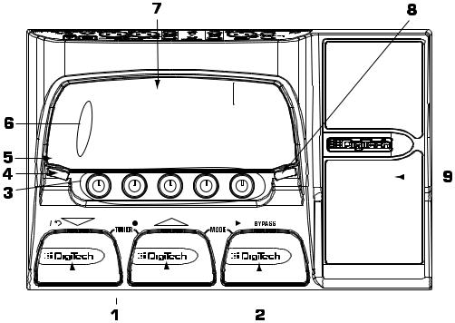
1. |
Down/Up Footswitches - These two footswitches are used to select presets, or access the Tuner of the |
|
|||||||||
|
Vx400. The footswitch on the left decreases, and the middle footswitch increases the preset |
|
|||||||||
|
number. Press and hold both Footswitches to access the Tuner. |
|
|||||||||
2. |
Bypass Footswitch - This footswitch bypasses the selected preset. It is also used in conjunction with the |
|
|||||||||
|
Up Footswitch to access the recorder functions when the Vx400 is connected to your computer |
|
|||||||||
|
via USB. |
1 |
|||||||||

Introduction
3. Knobs - These knobs perform various functions depending on which mode is selected or whether the Vx400 is connected to your computer via USB. During performance, the knobs control the Bass EQ, Mid EQ, Mid Frequency,Treble EQ, and Master Level. If the Vx400 is connected to the computer via USB, the performance functions of knobs 2, 3, and 4 are Playback Mix, USB 1-2 Send Level, and USB 3-4 Send Level. When editing or accessing the Setup functions, the knobs adjust the parameter values listed directly above each knob for the selected effect. When the Drum Machine is on, the knobs control the Pattern,Tempo, and Level. In Tuner mode, the knobs are used to select the tuning reference.
4. Select Button - This button enters the Edit mode and selects individual effects to be edited. Successive presses of this button advances through all available effects. You can also use the select button to perform two shortcuts. First, you can exit from anywhere within Edit mode by pressing and holding the Select button. Second, you can move directly to the setup row of the Matrix while in Performance mode by pressing and holding the Select button.
5. Drums - The Drums button turns the built-in drum machine on and off. When the drum machine is active, the Drums LED lights and the selected drum pattern plays continuously.
6. Matrix - The matrix provides information regarding the current preset, and parameter edit functions. In performance mode, the LED’s running down the left side of the Matrix identify which effects are in use for the selected preset. In Edit mode, the LED's indicate the effect selected for editing.
7. Display - The display provides information for different functions depending on the mode that is active. In Performance mode, the display shows the selected preset name and numeric location. In Edit mode, the display shows the name and value of the selected parameter. In Tuner mode, the display shows the note being played and whether the note is sharp, flat, or in tune.
8.Store - The Store button saves your changes to a User Preset.
9.Expression Pedal - The Expression Pedal controls up to three of the Vx400’s simultaneously assigned Effect
Parameters in real time. Almost every Parameter is available for Expression Pedal control.
Rear Panel
1.Instrument In - Connect your instrument to this jack.
2.Mic Level - Controls the gain of the Mic Input.
2
Introduction
3. Mic Input - Connect a mic here for recording or live performance mixing of acoustic sources into the Vx400. Mic signals can remain dry or be processed through the Vx400 effects for both live and recording applications. The Mic Input accepts either dynamic or phantom powered condenser microphones.
4. Left/Right Line Inputs - Connect line level sources to these jacks for recording or live performance mixing into the Vx400. Line signals can remain dry or be processed through the Vx400 effects for live and recording applications.
5. CD/Monitor In - Connect the output of a CD or MP3 player headphone out for listening to music. The CD/Monitor In can also be used as a monitor input for mixing the output of your computer’s sound card back into the Vx400 for playback monitoring.
Note: Using the CD/Monitor input for any type of real-time recording monitoring may result in a time delay depending on your computer’s speed.
6.Headphones - Connect a pair of stereo headphones to this 1/8” jack.
7.1/4” Line Outputs - Connect these outputs to your amplifier or to a mixing console that accepts 1/4”
unbalanced connections.
8. Balanced Line OutputsConnect these outputs to your power amplifier/speaker system or to a mixing console that accepts balanced XLR connections.
9. USB Jack - Connect this jack to your computer’s USB port for recording purposes (see page 25 for more on using the Vx400’s USB functions).
ATTENTION: The Vx400 can be connected to your computer before installing the USB drivers if you are using Windows XP™. However, if you are using any software other than
Windows XP, you must install the USB drivers provided on the X-Edit Software CD before connecting the Vx400 to your computer with the USB cable.
10. Footswitch jack - Connect the RPxFC 3-button footswitch to this jack.The RPxFC provides remote control of the recording functions of the Vx400 (see page 31 for more on using the RPxFC functions).
11. Power Input - Connect only the DigiTech PS0913B power supply to this jack.
3
Introduction
Making Connections
There are several different connection options available with the Vx400. Before connecting the Vx400, make sure that the power to your amplifier and the Vx400 is turned off. The Vx400 does not have a power switch. To turn the Vx400 off, disconnect the included PS0913B power supply from the power jack to an AC outlet.
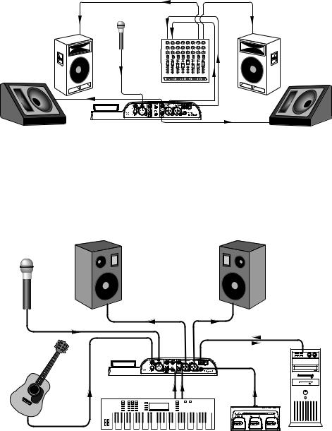
PA Rig
Connect your microphone to the Input of the Vx400. Connect the balanced XLR Left and Right outputs to the inputs on your PA mixer and pan each of these channels hard left and hard right. Select FULL as your Output Mode (see Output Modes on pg 19 on how the XLR and 1/4” outputs can be implemented for various recording and live applications).
1 |
2 |
3 |
4 |
5 |
6 |
7 |
8 |
Recording Setup
This is the classic recording setup utilizing the Vx400’s mic, instrument and line inputs with a pair of powered reference monitors connected the Vx400’s XLR outputs. This setup can also be used for live applications where you would be performing along with playback from the Pro Tracks recording software running on your computer (see the Output Modes section on page 19 on how the XLR and 1/4” outputs can be implemented for various recording and live applications).
 USB Ports
4
Introduction
Applying Power
Before applying power to anything, set your mixer to a flat EQ response (on most mixers, this would be 0). Then do the following:
1.Pull the Mixer’s Master Faders down completely.
2.Connect the plug of the PS0913B power supply to the Power Jack.
3.Connect the other end of the PS0913B power supply to an AC outlet.
4.Turn the Vx400 Master Volume up to 70 (70).
5.Push the Mixer’s Master Faders up to your desired level.
5
Introduction
The Presets
Presets are named and numbered locations of programmed sounds which reside in the Vx400. Presets are recalled with the footswitches. The active effects in each preset are indicated by the lighted LED's in the Effect Matrix. The Vx400 comes with 40 User Presets (Presets 1-40), and 40 DigiTech factory presets (4180). The User Presets are locations where you can store your edits. You may not store changes to the Factory Presets. From the factory, the 40 User Presets are exact duplicates of the 40 Factory Presets.
Performance
When you first apply power to the Vx400, it powers up in Performance mode. Performance mode provides access to all of the presets within the Vx400 via the Up and Down Footswitches. The Number 1 Knob (left) adjusts the Bass, the Number 2 Knob (second from the left) adjusts the amount of Midrange enhancement, the Number 3 Knob (middle) adjusts the Mid Frequency, the Number 4 Knob (second from the right) adjusts the amount of Treble (high frequency) enhancement, and the Number 5 Knob (right) adjusts the Master Level (volume).
Bypass
The Vx400 Presets can be bypassed for clean, unprocessed vocals and instrument signals. To bypass the Vx400, press the BYPASS Footswitch. The display will read Bypass indicating the preset is bypassed. Pressing the Up or Down Footswitches advances to the next available preset. Pressing the Bypass Footswitch again exits you from Bypass and loads that preset.
Tuner
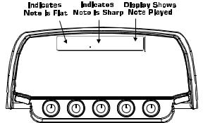
The Tuner lets you quickly tune or check the tuning of any instrument plugged into the Vx400. Enter Tuner mode by pressing and holding the Up and Down Footswitches simultaneously. The display briefly shows tuner indicating that you are in Tuner mode. To begin tuning, play a note on your instrument (a harmonic at the 12th fret usually works best for guitars). The right 2 characters in the display shows the note being played. The left characters in the display indicate whether you are sharp or flat. Arrows pointing to the left (<<<) indicate the note is sharp and should be tuned down. Arrows pointing to the right (>>>) indicate the note is flat and should be tuned up. When the note is in tune, the display shows --><--.


 >>><<< A


In Tuner mode, you can change your tuning reference. The default factory setting is A=440 Hz. (displayed as A=440). Rotate the Number 1 Knob to select alternate dropped tunings. Alternate tunings are A = Ab , A = G , and A = Gb. The display window briefly flashes the selected tuning preference.
The output is muted in Tuner mode. The Expression Pedal returns sound to the output allowing signal to be heard while tuning. Exit tuner mode by pressing any of the 3 Footswitches.
6
Introduction
CD/Monitor In
The CD In feature lets you connect a CD, MP3, or tape player to the Vx400, and play along with your favorite artists. To use the CD In feature, do the following:
1.Connect the headphone output of your MP3/CD/tape player to the CD/Monitor input using an 1/8” stereo cable.
2.Press play on your MP3/CD/tape player. The signal from your MP3/CD/tape player is routed to the left, right, and headphone outputs of the Vx400.
The Monitor In feature can also be used as a monitor input for mixing the output of your computer’s sound card back into the Vx400 for playback monitoring.
Drum Machine
The Vx400 features a Drum machine that includes several sampled drum patterns which are useful for developing a good sense of timing. Pressing the Drums button turns on the built-in drum machine (except when in Store or Bypass mode). When the drum machine is active:
The Number 1 Knob is used to select the drum Pattern. Choices include:
ROCK 1 |
HROCK4 |
DANCE1 |
blues2 |
urban1 |
|
ROCK 2 |
POP1 |
DANCE2 |
jazz |
urban2 |
|
ROCK 3 |
POP2 |
DANCE3 |
funk 1 |
reggae |
|
HROCK1 |
POP3 |
cntry1 |
funk 2 |
cha |
1 |
HROCK2 |
POP4 |
cntry2 |
swing1 |
cha |
2 |
HROCK3 |
POP5 |
blues1 |
swing2 |
BOSSA |
|
|
|
|
|
mtrnom |
|
The Number 2 Knob adjusts the drum Tempo and ranges from BPM 40 (40 beats per minute) to BPM240 (240 beats per minute).
The Number 3 Knob adjusts the volume Level of the drum loop and ranges from 1 to 99. Press the Drums button again to stop playback of the drum loop.
Mic Input and Level
The Vx400 features a mic input that can be used for mixing or recording vocals and acoustic instruments. The mic input is equipped with phantom power that can power professional condenser microphones. The mic preamp is controlled via the Mic Level knob for controlling the gain of the mic signal. To set the mic level control, follow these steps:
1.Connect a set of headphones to the headphone jack.
2.Sing or play at the loudest volume you will be performing at and adjust the mic Level control until you see the Clip LED at the top of the Matrix light. Then gradually decrease the control until the light goes out. This is the optimum setting for the Mic Level.
For application uses of the mic input, see both the Making Connections and Vx400 Setups sections of this user’s guide.
7

Creating Presets
Editing/Creating Presets
Creating your own signature sound with the Vx400 is easy and intuitive. The Vx400 lets you create your own presets, or fine tune existing presets to suit your needs. When creating or editing a sound, you must start with one of the User or Factory Presets. It is not possible to start with an empty preset. The preset number does not need to be the location that you intend to save it to, because you can save it to any User Preset location during the store process.
To edit or create a Preset:
1.Use the Up or Down Footswitches to select a preset.
2.Once you have found a preset that you want to edit, press the Select button once to enter Edit mode.
3.Use the Select button in conjunction with the Matrix LED's to choose the effect you want to edit. Successive presses of the Select button advance to the next Effect in the Matrix.
4.Use Knobs 1-4 to change parameter values.
5.Store your preset (See this page for more on storing a preset).
W


 LO-FI 17


The Matrix
The Matrix identifies the effects and parameters selected for editing. In Edit mode, successive presses of the Select button advances to the next row of effects. The LED lights indicating which effect group is selected. Each effect group has up to 4 parameters that can be modified. The knob directly below each column is used to change the parameter value of the selected effect. As a knob is rotated, the corresponding parameter’s name and value or status are displayed.
When the stored value of a parameter is changed, the Store LED lights indicating you need to store the changes. Changing presets, or turning the power off before storing erases all changes made and the Vx400 reverts to the stored values for the preset.
Storing/Copying/Naming a Preset
Once the preset is modified, you may store your settings to any of the 40 User Preset locations (Presets 1- 40). The following steps outline the procedure for storing changes to a preset or copying a preset to a different location:
1.Press the Store button once. The Store button LED blinks and the first character in the display flashes indicating you can name your new preset.
82. Use Knob 1 or Up/Down Footswitches to select the alpha-numeric character.
 Loading...