


 Vocalist VR


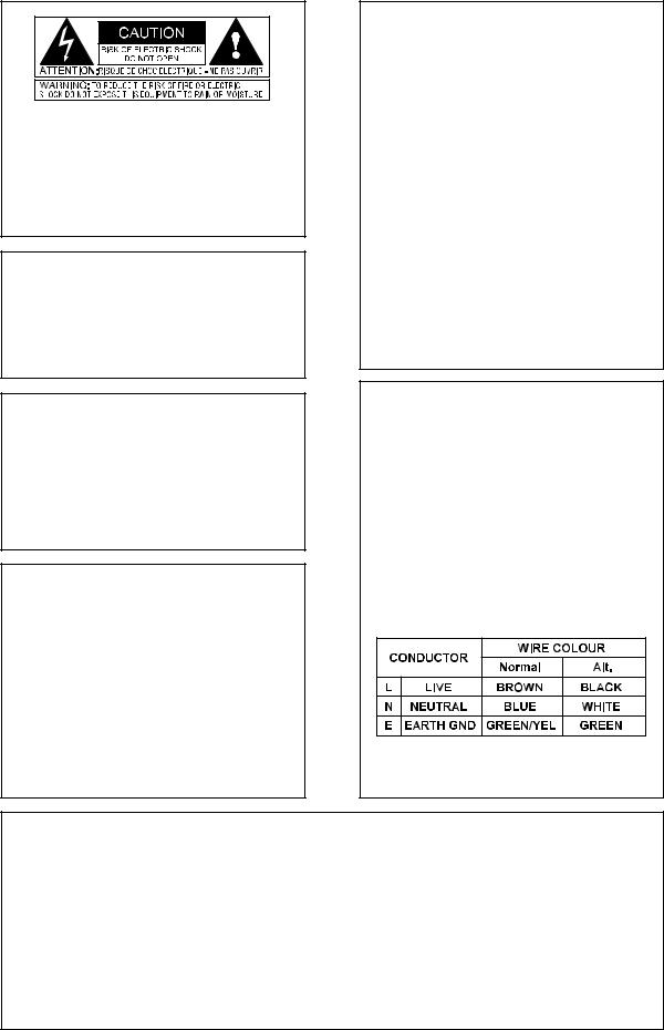
The symbols shown above are internationally accepted symbols that warn of potential hazards with electrical products. The lightning flash with arrowpoint in an equilateral triangle means that there are dangerous voltages present within the unit. The exclamation point in an equilateral triangle indicates that it is necessary for the user to refer to the owner’s manual.
These symbols warn that there are no user serviceable parts inside the unit. Do not open the unit. Do not attempt to service the unit yourself. Refer all servicing to qualified personnel. Opening the chassis for any reason will void the manufacturer’s warranty. Do not get the unit wet. If liquid is spilled on the unit, shut it off immediately and take it to a dealer for service. Disconnect the unit during storms to prevent damage.
U.K. MAINS PLUG WARNING
A moulded mains plug that has been cut off from the cord is unsafe. Discard the mains plug at a suitable disposal facility. NEVER UNDER ANY CIRCUMSTANCES SHOULD YOU INSERT A DAMAGED OR CUT MAINS PLUG INTO A 13 AMP POWER SOCKET. Do not use the mains plug without the fuse cover in place. Replacement fuse covers can be obtained from your local retailer. Replacement fuses are 13 amps and MUST be ASTA approved to BS1362.
WARNING
FOR YOUR PROTECTION, PLEASE READ THE FOLLOWING:
Water and Moisture: Appliance should not be used near water (e.g. near a bathtub, washbowl, kitchen sink, laundry tub, in a wet basement, or near a swimming pool, etc). Care should be taken so that objects do not fall and liquids are not spilled into the enclosure through openings.
POWER SOURCES: The appliance should be connected to a power supply only of the type described in the operating instructions or as marked on the appliance.
GROUNDING OR POLARIZATION: Precautions should be taken so that the grounding or polarization means of an appliance is not defeated.
POWER CORD PROTECTION: Power supply cords should be routed so that they are not likely to be walked on or pinched by items placed upon or against them, paying particular attention to cords at plugs, convenience receptacles, and the point where they exit from the appliance.
SERVICING: To reduce the risk of fire or electric shock, the user should not attempt to service the appliance beyond that described in the operating instructions. All other servicing should be referred to qualified service personnel.
CAUTION: To reduce the risk of fire replace only with same type fuse. ATTENTION: Utiliser un fusible de recharge de même type.
CAUTION: To reduce the risk of fire replace LAMP with manufacturers recommended part ( Refer to service literature)
ELECTROMAGNETIC
COMPATIBILITY
This unit conforms to the Product Specifications noted on the Declaration of Conformity. Operation is subject to the following two conditions:
•this device may not cause harmful interference, and
•this device must accept any interference received, including interference that may cause undesired operation. Operation of this unit within significant electromagnetic fields should be avoided.
•use only shielded interconnecting cables.
FCC COMPLIANCE
This equipment has been tested and found to comply with the limits for a Class B digital device, pursuant to Part 15 of the FCC Rules. These limits are designed to provide reasonable protection against harmful interference in a residential installation. This equipment generates, uses and can radiate radio frequency energy and, if not installed and used in accordance with the instructions, may cause harmful interference to radio communications. However, there is no guarantee that interference will not occur in a particular installation. If this equipment does cause harmful interference to radio or television reception, which can be determined by turning the equipment off and on, the user is encouraged to try to correct the interference by one or more of the following measures:
•Reorient or relocate the receiving antenna
•Increase the separation between the equipment and receiver that may cause undesired operation.
•Connect the equipment into an outlet on a circuit different from that to which the receiver is connected
•Consult the dealer or an experienced radio/TV technician for help.
SAFETY INSTRUCTIONS
Notice For Customers If Your Unit Is Equipped With A Power Cord. WARNING: THIS APPLIANCE MUST BE EARTHED.
The cores in the mains lead are coloured in accordance with the following code:
GREEN and YELLOW - Earth BLUE - Neutral BROWN - Live
As colours of the cores in the mains lead of this appliance may not correspond with the coloured markings identifying the terminals in your plug, proceed as follows:
•The core which is coloured green and yellow must be connected to the terminal in the plug marked with the letter E, or with the earth symbol, or coloured green, or green and yellow.
•The core which is coloured blue must be connected to the terminal marked N or coloured black.
•The core which is coloured brown must be connected to the terminal marked L or coloured red.
This equipment may require the use of a different line cord, attachment plug, or both, depending on the available power source at installation. Connect this equipment only to the power source indicated on the equipment rear panel. If the attachment plug needs to be changed, refer servicing to qualified service personnel who should refer to the table below. The green/yellow wire shall be connected directly to the unit's chassis.
WARNING: If the ground is defeated, certain fault conditions in the unit or in the system to which it is connected can result in full line voltage between chassis and earth ground. Severe injury or death can then result if the chassis and earth ground are touched simultaneously.
DECLARATION OF CONFORMITY
|
|
|
Supplementary Information: |
Manufacturer’s Name: |
IVL Technologies Ltd. |
The product herewith complies with the requirements of the EMC Directive |
|
|
|
per DigiTech specifications |
89/336/EEC (1989) and the Low Voltage Directive 73/23/EEC as amended by the CE |
Manufacturer’s Address: |
6710 Bertram Place |
Marking Directive 93/68/EEC (1993). |
|
|
|
Victoria, B.C. |
|
|
|
Canada V8M 1Z6 |
IVL Technologies Ltd. |
declares that the products: |
DigiTech Vocalist ACCESS |
6710 Bertram Place |
|
|
|
|
Victoria, B.C. |
conform to the following product specifications: |
Canada V8M 1Z6 |
||
|
|
|
July 31st, 1998 |
EMC: |
EN 55022 (1987): |
Brian Gibson, Vice President of Engineering |
|
|
CISPR 22 (1993) Class B |
|
|
|
EN 50082-1 (1992) |
European Contact: Your local DigiTech Sales and Service Office or |
|
|
|
|
International Sales Office |
Safety: |
EN 60065 (1997) |
3 Overlook Drive Unit #4 |
|
|
IEC65 (1985) with amendment 1,2,3 |
Amherst, New Hampshire 03031, USA Tel (603) 672-4244 Fax (603) 672 4246 |
|

VOCALIST VR
AC Power & Safety Warnings |
....................................................................................... |
inside cover |
Introduction..................................................................................................................................... |
|
2 |
Jump Start........................................................................................................................................ |
|
3 |
Program List.................................................................................................................................... |
|
3 |
Setup ............................................................................... |
Front Panel |
4 |
................................................................................ |
Back Panel |
5 |
...................................................................... |
Set - Up Examples |
6 |
............................................................................ |
Factory Reset |
7 |
Performance ....................................... |
Setting Levels, Getting a good signal |
8 |
........................................................................ |
Loading Presets |
8 |
.......................................................................... |
Storing Presets |
8 |
............................. |
Setting Harmony, Reverb, and Lead Levels |
9 |
........................................................ |
Harmony Control Modes |
10 |
....................................................................................... |
Scale |
10 |
...................................................................................... |
Chord |
10 |
...................................................................................... |
Notes |
11 |
.................................................................................... |
Double |
11 |
............................................................... |
Aux Input to Reverb |
12 |
Editing ............................................................. |
The EDIT Parameters |
13 |
..................................................... |
Preset Specific Parameters |
13 |
.................................................................. |
Global Parameters |
15 |
.................................................................. |
Harmony Voicing |
16 |
External Control .............................................................................. |
Footswitch |
18 |
................................................................. |
Main and Alt Keys |
18 |
................................................ |
Using MIDI Control Changes |
19 |
Basic Harmony Concepts.............................................................................................................. |
|
21 |
Appendix 1 - Reverb Types........................................................................................................... |
|
24 |
Appendix 2 - Specifications........................................................................................................... |
|
25 |
Appendix 3 - MIDI .................................................... |
MIDI implementation chart |
26 |
Appendix 4 - Scale Chart............................................................................................................... |
|
27 |
1

Buying a new piece of gear isisusuallyaadifficultficultdecision--whatmakeshouldititbe?be?whatdoesdoesitit
do? how much?? etc.? This isis whyweweappreciateyouyoupurchasingthetheDigitechVocalistVOCALISTAC ESS. VR. You might be iinterested in knowing thatthetheengineerswhodesignedtheVocalistACCESSVOCALISTshareVR share
aa lott in commonwithyouyou..TheTheengineersbehindACCESSVOCALISTbelieveVR thebelievevoicetheisvoicea specialis specialinstru- instrument mentand theyand wantthey wantit to soundit to soundevenevenbetterbetter. Employing. Employingvocalvocalharmonyharmonytechnologytechnologyand reverband reverb
effects, VOCALISTAC ESS wasVRdesignedwas designedwith easywithoperationeasy operationin mindin. Ourmindengineers. Our engineersare usingareACCESSusing VOCALIST VR forr gigging and recording on the weekend.. Whenever andd wherever you use it we trust you will
like the results.
Features:
 Plug it in and Play - easy to use interface
 4 voices of natural-sounding harmony
 Three harmony control options balance ease of use and melodic flexibility
 4 voice automatic doubling for vocal thickening
 10 reverb types to enhance the lead and harmony voices
 AUX input to Reverb allows sharing of the reverb effect with other instruments
 50 user-editable presets
 Extended utility via optional external footswitch
 Extra expression capabilities via MIDI controller parameters
2
VOCALIST VR
Plug in the external power supply and turn ACCESSVOCALISTon.VRConnect. Connecta microphonea microphoneto toACCESSVOCALISTvia theVRfrontvia panelthe frontXLRpaneljack.XLR jack.
Connect the stereo outputsofofACCESSVOCALISTto inputsVR tooninputsyour onmixer,yourintelligentmixer, intelligentkeyboardkeyor- boardanythingoranythingwith speakerswith speakersat the endat. the end.
Prressthe Bypassbutton sosoitit lights.. While singinginto your mic raise the input level until the Signal LED is lighting orange with some quick peaks of red on your loudestest notes.
Take VOCALISTAC ESS outVRof Bypassout of Bypass. Use the. Useknobtheclosestknob closestto the LCDto thedisplayLCD displayto selecttoaselectpre- a preset. .
Enjoy and listen. Keep in mind that presets that say “notes” in the LCD display require
Enjoy and listen. Keep in mind that presets that say “notes” in the LCD display require
a keyboard to produce harmonies. Hook one up if you’ve got it. a keyboard to produce harmonies. Hook one up if you’ve got it.
After you have got some sounds out of VOCALIST VR and impressed your friends, go
After you have got some sounds out of ACCESS and impressed your friends, go to your
to your favorite room, with your favorite chair and entertain yourself by reading this favorite room, with your favorite chair and entertain yourself by reading this manual -
manual - just think how impressed your high school english teacher would be. just think how impressed your high school english teacher would be.
Program List
Programs 1 through 10 are “Scale” programs. Scale programs allow you to set the key and scale at the beginning of a song and they will follow your vocal melody automatically from then on. The factory programs have been set to E Major (programs 1-5) and E Minor (programs 6-10). You can change the key and scale by pressing the edit button and turning the parameter knob.
Programs 11 through 20 are “Chord” programs. You will need a MIDI keyboard to control the harmonies. Play the chords of a song on the keyboard while you sing and the harmonies will change in order to stay musically in tune with you.
Programs 21 through 25 are the “Notes” programs. This is another MIDI keyboard-controlled harmony mode. Whatever notes you play on the keyboard become the harmony notes when you sing. This is useful for creating moving harmony lines while you sing one long note for example.
Programs 26 through 41 are Scale mode templates for you to build your own programs upon. They have been preset to the keys of G, A, D and C with the four Major and Minor scales.
Programs 42 through 46 are the doubling and effects programs.
Programs 47 through 50 are the ROM (Read Only Memory) programs. It is not possible to overwrite these programs. These are included to ensure that there is at least one program of each harmony mode type in case all others are overwritten.
3
Front Panel
VOCALIST VR
1 |
2 |
3 |
4 |
5 |
6 |
7 |
8 |
9 |
10 |
11 |
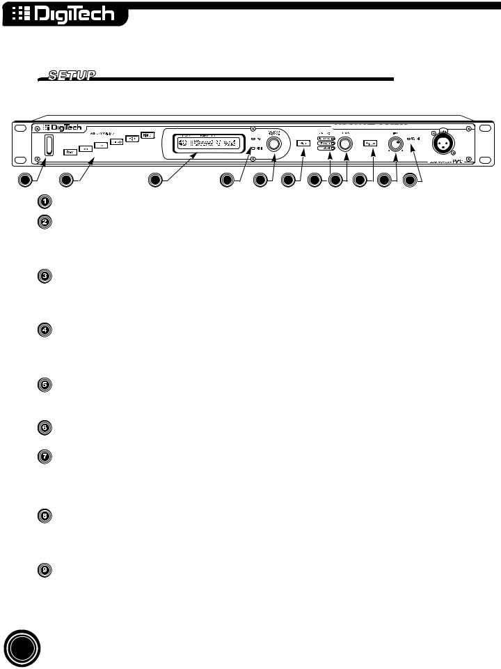
Power Switch
Harmony Voicing Buttons allow you to adjust the voicing of harmonies. The High and Higher buttons create harmonies above your voice. The Low, Lower and Bass buttons creates harmonies below your voice. The Double button creates detuned unison copies of your voice. See page 16 for more detail on Harmony Voicing.
The LCD Display shows preset number and harmony mode information at the initial level. It is also used to show editing and level information. Note that the “a” after the preset number is only shown when the optional FS 300 footswitch is connected. See page 18 for more details.
Data LEDs
 Edit LED lights when ACVOCALISTESS is inVREditis inmodeEdit mode
 MIDI LED lightsts when ACCESSVOCALISTis receivingVR is receivingMIDI onMIDIany chanon anyelchannel. .
Data Entry Knob/Switch - is it a knob or a switch? It’s both. Turn the knob to select presets. Push the knob to access the edit screen in the LCD display. This control is used for editing, and preset selection. For more details see page 8 or 13.
The Store Button allows you to save any changes you’ve made to a preset into user memory. It also lights to show that you’ve made a change to a program.
Level LEDs (see page 9 for more detail):
 Harmony LED lights when the Level Knob/Switch controls harmony level.
 Reverb LED lights when the Level Knob/Switch controls reverb level.
 Lead LED lights when the Level Knob/Switch controls lead level.
Level Knob/Switch - just like the Data Entry control, the level control is both a knob and a switch. Use it as a switch to select which level you want to adjust (harmony, reverb, or lead). Use it as a knob to adjust the level. Visual feedback is provided by the LCD Display.
Bypass Button mutes the Harmonies from the stereo mix output. If there is Lead Vocal and/or reverb in the mix they will be uneffected by the bypass button.
4
VOCALIST VR
Input Level Knob adjusts the inputlevell for the microphonehone andlineinputs. .
The Signal LED guides you to an optimalal llevel setting. The LED llights in tthree colors.
 Green• isdisplayedwhenACCESSVOCALISTcan recognizeVR can recognthe pitchze theof yourpitchvoiceof your voice
 Orange• is displayedwhenACCESSVOCALISTis generatingVR is generatingoptimal signaloptimalto signalnoise.to noise.
 Red• RedisisdisplayedwhenACCESSVOCALISTis justVRbelowis justclippingbelow -clippcausing-uglycausingdigitalug ydistortiondigital distortion
Back Panel
VOCALIST VR
1 |
2 |
3 |
4 |
5 |
6 |
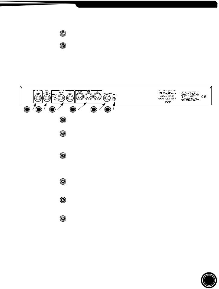
Line Input accepts mono line level audio from an external source. This jack overrides
Line Input accepts mono line level audio from an external source. This jack overrides the front panel MIC jack.
the front panel MIC jack.
AUX Input to Reverb bypasses the harmony processing and routes the AUX signal
AUX Input to Reverb bypasses the harmony processing and routes the AUX signal
directly to the reverb effect. This feature allows you to ‘borrow’ VOCALIST VR’ reverb directly to the reverb effect. This feature allows you to ‘borrow’ ACCESS’ reverb effect
effectfor other instruments that don’t need harmonies. The input accepts mono line level for other instruments that don’t need harmonies. The input accepts mono line level
audio from an external source. audio from an external source.
Left and Right Outputs are the main mix outputs. The outputs have a selectable output
Left and Right Outputs are the main mix outputs. The outputs have a selectable output
level using the level switch beside the outputs - +4dBu or -10dBu. Use the switch to level using the level switch beside the outputs - +4dBu or -10dBu. Use the switch to
match the output of VOCALIST VR to your mixer. For mono output use the left out- match the output of ACCESS to your mixer. For mono output use the left output on its
put on its own. |
|
|
own. |
|
|
MIDI thru/out/in are used to control |
VR with an external MIDI device. MIDI |
|
MIDI thru/out/in are used to controlVOCALISTCESS with an external MIDI device. MIDI IN |
||
IN receives MIDI information. MIDI THRU transmits an |
of any MIDI informa- |
|
receives MIDI information. MIDI THRU transmits an exact copy of any MIDI informa- tiontionrreceivedatatthetheMIDIIN..
Footswitch input is used to connect a Digitech FS-300 footswitch to provide remote
Footswitch input is used to connect a Digitech FS-300 footswitch to provide remote controlofofBypass,Bypass,ReverbReverbon/off,on/off,andand‘ALTernate’‘ALTernate’KeyKey. See. Seepage18page18forformoremoreinformainforma- - tion)..
Power input is used only with a Harman Pro Group PS750 9.75V AC, 820mA power
Power input is used only with a Harman Pro Group PS750 9.75V AC, 820mA power adaptersuppliedwithwiththetheunit..
5

Set-Up Examples
Live Performance
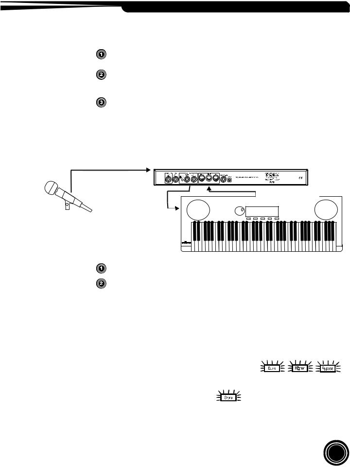
The line-drawing below represents a typical live performance set-up. The keyboard is optional depending on how you want to control your harmony parts (see Harmony Control Modes for more information on page 10). Connect as follows:

 audio from mic to VOCALIST VR
MIDI from keybard
 to VOCALIST VR
 audio from
VOCALST VR
 to mixer
connect microphone to frontt panelMICinputofofACCESSVOCALIST VR
connect stereo outputs of ACCESSVOCALISTto aVRstereoto ainputstereorinputtwo monoor twoinputsmononinputsyo r mixeron your mixer
(headphones or amplifier and speakers aree neededed to monitor audio))..
connect keyboard MIDII outtoACCESS’VOCALISTMIDIVR’inMIDIif using iftheusingChordtheorChNordtesorharmonyNotes harmony control modes.
Acoustic Instrument Performance
VACOCALISTESS worksVR greatworksforgreatacousticfor acoubasticed groupsbased groups. No MIDI. No inputMIDIneededinput neededhere. ThehereAUX. TheinputAUXtoinput tothereverbreverbisisusefulusefultotoaddaddsomesomedepthdepthtotoyouryoursoundsound. Connect. Connectasasfollows:
AUX send of lead vocal
to line input of Vocalist VR
AUX send of other channels
to Vocalist VR AUX input 
 for reverb

audio from Vocalist VR to mixer
6
VOCALIST VR
connect a microphone to MICchannelononyourmixerandanyanyotherinstrumentstotootherother channelsa ls on your mixer..
send lead vocalsignalfrommixer(via(viaoneoneofofthethemixer’sAUXAUXsends)sends)totothethelinelineinputinput off VOCALISTAC ESS. SendVR.otherSendinstrumentother instrumentsignals signalsfrom mixerfrom (vmixera a separate(via parateAUX AUXsend) send)to tothetheACCESS’VOCALISTAUXVR’inputAUXto addinputreverbto addto yourreverbmixto.your mix.
connectct stereoreo outputs of ACVOCALISTESS to aVRstereoto ainputstereoorinputtwo monoor twoinputsmonooninputsyour onmixeryour mixer(headp(headphonesor amplifieror amplifierand speakersand speakersare neededare neededto monitormonitoraudio).audio).
Intelligent Arranger Keyboard with built in speakers
Intelligent Arranger Keyboard with built in speakers
Many keyboards have a stereo AUX input. Send your outputs from the VOCALIST VR to your
Many keyboards have a stereo AUX input. Send your outputs from ACCESS to your keyboard to keyboard to mix harmonies, your voice, and keyboard arrangements the way you want to hear
mix harmonies, your voice, and keyboard arrangements the way you want to hear them.Connect them.Connect as follows:
as follows:
audio from mic  to VOCALIST VR
MIDI from keyboard
to VOCALIST VR
audio from VOCALIST VR |
to line inputs on keyboard |
connectt microphonephone totofrontpanelMICinputofofACCESSVOCALIST. VR.
connect MIDII outfromintelligent/arrangerkeyboardtotoMIDIininofofACCESSVOCALIST. ConnectVR.
ACCESS’Connect VOCALISTaudio outputVR’to theaudiol neoutinputtstontheyourlinekeyboardinputs on your keyboard
In the rack . . . In the studio
VOCALIST VR will interface with any studio console. The hook up diagram would be the
ACCESS will interface with any studio console. The hook up diagram would be the same as the
same as the Acoustic Performance setup on the previous page.
Acoustic Performan e setup on the previ us page.
Factory Reset
To iniitialize VOACCESSALISTto itsVRstateto itswhenstateitwhenleft theit leftfactory,the factory,press 


 atpresstheatsameth tisame. timeThe .LCDThe DisplayLCD Dispwillaypromptwill promptyou if you ifwouldyou wouldlike tolike“Confirmto “ConfirmReset”.
Reset”.
To follow through with the initialization press 


 . The LCD Display will confirm by stating “Factory Restore”. Initialization will overwrite any custom presets you may have created.
7
 Loading...