


RP-12 Owner’s Manual
DECLARATION OF CONFORMITY
Manufacturer’s Name: |
Digitech |
Manufacturer’s Address: |
8760 S. Sandy Parkway |
|
Sandy, Utah 84070, USA |
declares that the product: |
|
Product Name: |
RP-12 |
Product Options: |
All (requires a Class II power adapter that conforms to the require- |
|
ments of EN6005, EN60742, or equivalent). |
conform to the following Product Specifications: |
|
Safety: |
EN 60065 (1993) |
|
IEC 65 (1987) with Amendments 1, 2 & 3 |
EMC: |
EN 55013 (1990) |
|
EN 55020 (1991) |
Supplementary Information:
The product herewith complies with the requirements of the Low Voltage Directive 73/23/EEC and EMC Directive 89/336/EEC as amended by Directive 93/68/EEC.
.
Digitech
President of Digitech
8760 S. Sandy Parkway
Sandy, Utah 84070, USA
Effective October 17, 1996
European Contact: Your Local DigiTech Sales and Service Office or
International Sales Office
3 Overlook Drive #4
Amherst, New Hampshire 03031, USA
Tel (603) 672-4244
Fax (603) 672-4246

RP-12 Owner’s Manual
|
Table Of Contents . . . . . . . . . . . . . . . . . . . . . . . . . . |
1 |
1 |
|
Introduction . . . . . . . . . . . . . . . . . . . . . . . . . . . . . . . |
4 |
|
|
Safety Precautions . . . . . . . . . . . . . . . . . . . . . . . . . |
4 |
|
|
Lithium Battery Warning . . . . . . . . . . . . . . . . . . |
5 |
|
|
Warranty . . . . . . . . . . . . . . . . . . . . . . . . . . . . . . . . . |
6 |
|
SECTION 1 - STARTUP |
Supplying power . . . . . . . . . . . . . . . . . . . . . . . . . . . |
7 |
|
|
Line Conditioning. . . . . . . . . . . . . . . . . . . . . . . . . . . |
7 |
|
|
Front Panel Controls . . . . . . . . . . . . . . . . . . . . . . . . |
7 |
|
|
Pedalboard . . . . . . . . . . . . . . . . . . . . . . . . . . . . |
7 |
|
|
Display Window . . . . . . . . . . . . . . . . . . . . . . . . |
8 |
|
|
Program Buttons. . . . . . . . . . . . . . . . . . . . . . . . |
8 |
|
|
Parameter Buttons . . . . . . . . . . . . . . . . . . . . . . |
8 |
|
|
Effect Library Buttons . . . . . . . . . . . . . . . . . . . . |
8 |
|
|
Global Buttons . . . . . . . . . . . . . . . . . . . . . . . . . |
8 |
|
|
Main Output Level. . . . . . . . . . . . . . . . . . . . . . . |
9 |
|
|
Continuous Control Pedal . . . . . . . . . . . . . . . . . |
9 |
|
|
Rear Panel Connections . . . . . . . . . . . . . . . . . . . . . |
9 |
|
|
Input . . . . . . . . . . . . . . . . . . . . . . . . . . . . . . . . . |
9 |
|
|
Right Output . . . . . . . . . . . . . . . . . . . . . . . . . . . |
9 |
|
|
Left/Mono Output . . . . . . . . . . . . . . . . . . . . . . . |
9 |
|
|
Headphone Output . . . . . . . . . . . . . . . . . . . . . . |
9 |
|
|
AC Line Input . . . . . . . . . . . . . . . . . . . . . . . . . . |
9 |
|
|
MIDI In . . . . . . . . . . . . . . . . . . . . . . . . . . . . . . . |
9 |
|
|
MIDI Out / Thru. . . . . . . . . . . . . . . . . . . . . . . . . |
9 |
|
|
MIDI and Audio Setups . . . . . . . . . . . . . . . . . . . |
10 |
|
SECTION 2 - BASIC OPERATIONS |
Program Architecture. . . . . . . . . . . . . . . . . . . . . . . . |
12 |
|
|
Tuning with the RP-12 . . . . . . . . . . . . . . . . . . . . . . . |
13 |
|
|
Changing the Tuning Reference . . . . . . . . . . . . . . . |
14 |
|
|
Assigning Programs to Footswitches . . . . . . . . . . . . |
14 |
|
|
Assigning Parameters to Footswitches. . . . . . . . . . . |
15 |
|
SECTION 3 - PROGRAMMING |
Using the Function Keys . . . . . . . . . . . . . . . . . . . . . |
16 |
|
|
More Special Characters . . . . . . . . . . . . . . . . . . . . . |
16 |
|
|
The Effects Library Buttons . . . . . . . . . . . . . . . . . . . |
17 |
|
|
About the I / O Module. . . . . . . . . . . . . . . . . . . . . . . |
17 |
|
|
Modifying Factory Programs . . . . . . . . . . . . . . . . . . |
17 |
|
|
Basic Program Creation. . . . . . . . . . . . . . . . . . . . . . |
18 |
|
|
Selecting an Algorithm . . . . . . . . . . . . . . . . . . . |
18 |
|
|
Naming Programs. . . . . . . . . . . . . . . . . . . . . . . |
19 |
|
|
Storing Programs . . . . . . . . . . . . . . . . . . . . . . . |
19 |
|
SECTION 4 - EFFECTS AND PARAMETERS |
About the Effects Library . . . . . . . . . . . . . . . . . . . . . |
22 |
|
|
Analog Effects . . . . . . . . . . . . . . . . . . . . . . . . . . . . . |
22 |
|
|
Compressor . . . . . . . . . . . . . . . . . . . . . . . . . . . |
22 |
|
|
Distortion . . . . . . . . . . . . . . . . . . . . . . . . . . . . . |
22 |
|
|
Equalizers. . . . . . . . . . . . . . . . . . . . . . . . . . . . . |
23 |
|
|
Cabinet Emulator . . . . . . . . . . . . . . . . . . . . . . . |
24 |
|
|
Reverbs. . . . . . . . . . . . . . . . . . . . . . . . . . . . . . . . . . |
25 |
|
|
Gated Reverbs . . . . . . . . . . . . . . . . . . . . . . . . . |
29 |
|


 Table of Contents


|
RP-12 Owner’s Manual |
|
|
Delay / Sampler. . . . . . . . . . . . . . . . . . . . . . . . . . . . |
31 |
|
Delays . . . . . . . . . . . . . . . . . . . . . . . . . . . . . . . |
31 |
2 |
Sampler . . . . . . . . . . . . . . . . . . . . . . . . . . . . . . |
33 |
|
Pitch Shifters . . . . . . . . . . . . . . . . . . . . . . . . . . . . . . |
35 |
|
Detuners. . . . . . . . . . . . . . . . . . . . . . . . . . . . . . |
36 |
|
Whammy™. . . . . . . . . . . . . . . . . . . . . . . . . . . . |
37 |
|
Arpeggiators . . . . . . . . . . . . . . . . . . . . . . . . . . . |
37 |
|
Modulation Effects . . . . . . . . . . . . . . . . . . . . . . . . . . |
38 |
|
Choruses . . . . . . . . . . . . . . . . . . . . . . . . . . . . . |
38 |
|
Flangers . . . . . . . . . . . . . . . . . . . . . . . . . . . . . . |
39 |
|
Phasers . . . . . . . . . . . . . . . . . . . . . . . . . . . . . . |
40 |
|
Tremolos . . . . . . . . . . . . . . . . . . . . . . . . . . . . . |
40 |
|
Auto Panners . . . . . . . . . . . . . . . . . . . . . . . . . . |
41 |
|
Mixers . . . . . . . . . . . . . . . . . . . . . . . . . . . . . . . . . . . |
41 |
|
More . . . . . . . . . . . . . . . . . . . . . . . . . . . . . . . . . . . . |
42 |
|
Noise Gates . . . . . . . . . . . . . . . . . . . . . . . . . . . |
42 |
|
DSP Level . . . . . . . . . . . . . . . . . . . . . . . . . . . . |
43 |
|
Wahs . . . . . . . . . . . . . . . . . . . . . . . . . . . . . . . . |
43 |
|
Duckers . . . . . . . . . . . . . . . . . . . . . . . . . . . . . . |
44 |
|
Phase Inverter . . . . . . . . . . . . . . . . . . . . . . . . . |
44 |
SECTION 5 - RP-12 FUNCTIONS |
About the RP-12’s Internal Functions . . . . . . . . . . . . |
46 |
|
Pedalboard Functions . . . . . . . . . . . . . . . . . . . . . . . |
47 |
|
MIDI functions . . . . . . . . . . . . . . . . . . . . . . . . . . . . . |
48 |
SECTION 6 - PEDALBOARD SETUP |
Pedalboard Setup . . . . . . . . . . . . . . . . . . . . . . . . . . |
49 |
|
Pedals. . . . . . . . . . . . . . . . . . . . . . . . . . . . . . . . . . . |
50 |
|
Pedal Assignments . . . . . . . . . . . . . . . . . . . . . . |
50 |
|
Program Changes . . . . . . . . . . . . . . . . . . . . |
50 |
|
Program Up & Down . . . . . . . . . . . . . . . . . . |
50 |
|
List Up & Down . . . . . . . . . . . . . . . . . . . . . . |
50 |
|
Toggle CC 0-127 . . . . . . . . . . . . . . . . . . . . . |
50 |
|
CC Pedal 0-127. . . . . . . . . . . . . . . . . . . . . . |
50 |
|
CC Pedal. . . . . . . . . . . . . . . . . . . . . . . . . . . . . . . . . |
51 |
|
Assign CC Pedal . . . . . . . . . . . . . . . . . . . . . . . |
51 |
|
CC Pedal. . . . . . . . . . . . . . . . . . . . . . . . . . . |
51 |
|
Transmit . . . . . . . . . . . . . . . . . . . . . . . . . . . |
51 |
|
Calibrate Pedal . . . . . . . . . . . . . . . . . . . . . . . . . |
51 |
|
PrgList Assign . . . . . . . . . . . . . . . . . . . . . . . . . . . . . |
52 |
|
List size . . . . . . . . . . . . . . . . . . . . . . . . . . . . . . |
52 |
|
Steps . . . . . . . . . . . . . . . . . . . . . . . . . . . . . . . . |
52 |
|
LED Assign . . . . . . . . . . . . . . . . . . . . . . . . . . . . . . . |
53 |
|
Naming Banks . . . . . . . . . . . . . . . . . . . . . . . . . . . . . |
53 |
SECTION 7 - RP-12 SETUP |
Contrast . . . . . . . . . . . . . . . . . . . . . . . . . . . . . . . . . |
55 |
|
Output Mode . . . . . . . . . . . . . . . . . . . . . . . . . . . . . . |
55 |
|
Cabinet Emulation . . . . . . . . . . . . . . . . . . . . . . . . . . |
56 |
|
Sales Banner. . . . . . . . . . . . . . . . . . . . . . . . . . . . . . |
56 |
|
Reinitializing the RP-12 . . . . . . . . . . . . . . . . . . . . . . |
57 |

RP-12 Owner’s Manual
SECTION 8 - MIDI SETUP |
About the MIDI Set-Up. . . . . . . . . . . . . . . . . . . . . . . |
58 |
3 |
|
MIDI Channel . . . . . . . . . . . . . . . . . . . . . . . . . . . . . |
58 |
|
|
Send Program . . . . . . . . . . . . . . . . . . . . . . . . . . . . . |
58 |
|
|
Program Send Map . . . . . . . . . . . . . . . . . . . . . . . . . |
59 |
|
|
Devices . . . . . . . . . . . . . . . . . . . . . . . . . . . . . . |
59 |
|
|
Device Map . . . . . . . . . . . . . . . . . . . . . . . . . . . |
59 |
|
|
Program Receive Map . . . . . . . . . . . . . . . . . . . . . . . |
60 |
|
|
Assign CC # to a Parameter . . . . . . . . . . . . . . . . . . |
60 |
|
|
Display CCs . . . . . . . . . . . . . . . . . . . . . . . . . . . . . . |
63 |
|
|
Bulk Dump . . . . . . . . . . . . . . . . . . . . . . . . . . . . . . . |
63 |
|
|
Program Dump . . . . . . . . . . . . . . . . . . . . . . . . . . . . |
64 |
|
|
MIDI merge . . . . . . . . . . . . . . . . . . . . . . . . . . . . . . . |
65 |
|
SECTION 9 - APPENDIX |
Specifications . . . . . . . . . . . . . . . . . . . . . . . . . . . . . |
66 |
|
|
Factory Algorithm Diagrams. . . . . . . . . . . . . . . . . . . |
67 |
|
|
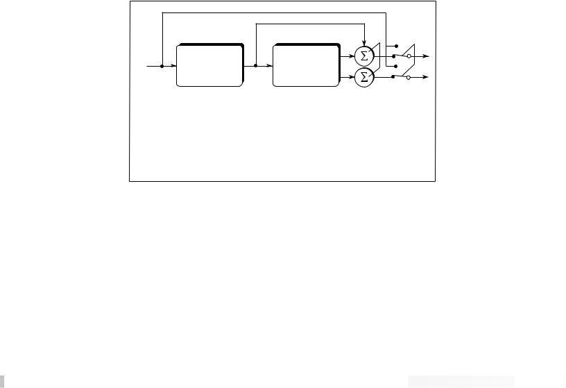
Block Diagram . . . . . . . . . . . . . . . . . . . . . . . . . . . . . |
77 |
|
|
MIDI Implementation Chart . . . . . . . . . . . . . . . . . . . |
78 |
|
|
Preset List . . . . . . . . . . . . . . . . . . . . . . . . . . . . . . . . |
79 |
|
|
Harmony Interval Chart . . . . . . . . . . . . . . . . . . . . . . |
81 |
|
4INTRODUCTION
SAFETY PRECAUTIONS
RP-12 Owner’s Manual
Congratulations, and thank you for purchasing the DigiTech RP-12 Guitar Signal Processor / Preamp. The RP-12 offers you a fresh approach to guitar sound creation, giving you the hottest tones and total control of the best digital effects in the industry. DigiTech’s revolutionary S-DISC II ™ processor makes it all happen. Its digital multieffects are second to none, and when you combine its power with the warmth and clarity of the best analog preamp on the market, with up to 10 real-time continuous controller links per Program, nothing else even comes close. Special features of the RP-12 include:
•Full bandwidth effects (20-20kHz)
•24-bit signal path, 48-bit internal data transmission
•Stereo Effects
•Instant Module and Parameter access
•Harmony/Intelligent Pitch Shifting
•Whammy™ effects
•Three Distortions types including Grunge™
•Silencer™ Noise Reduction
•Programmable cabinet emulation for running direct to a mixing console (great for both studio and live applications)
•Built in FX Continuous Controller Pedal
•Built-in MIDI merging
•MIDI Transmit and Receive mapping
•Extensive real-time MIDI control of effects and parameters
•New and improved Chromatic Tuner
For the first time, all of your effects needs can be filled by a single unit with 16-bit digital clarity. This owner’s manual is your key to understanding the powerful world of the RP-12. Read it carefully.
C A U T I O N |
RIS K O F ELECTRI C SHOCK |
D O NO T OPEN |
A TTEN TIO N: RISQU E D E CHO C ELECTRIQU E - N E PA S OUVRIR |
WAR NI NG : T O REDUC E TH E RIS K O F FIR E O R ELECTRIC
SHOC K D O NO T EXPOS E THI S EQUIPMEN T T O RAI N O R MOISTURE
The symbols shown above are internationally accepted symbols that warn of potential hazards with electrical products. The lightning flash with arrowpoint in an equilateral triangle means that there are dangerous voltages present within the unit. The exclamation point in an equilateral triangle indicates that it is necessary for the user to refer to the owner’s manual.

RP-12 Owner’s Manual
These symbols warn that there are no user serviceable parts inside5the unit. Do not open the unit. Do not attempt to service the unit yourself. Refer all servicing to qualified personnel. Opening the chassis for any reason will void the manufacturer’s warranty. Do not get the unit wet. If liquid is spilled on the unit, shut it off immediately and take it to a dealer for service. Disconnect the equipment during storms to prevent damage.
U.K. ONLY - A moulded mains plug that has been cut off from the cord is unsafe. Discard the mains plug at a suitable disposal facility. NEVER UNDER ANY CIRCUMSTANCES SHOULD YOU INSERT A DAMAGED OR CUT MAINS PLUG INTO A 13 AMP POWER SOCKET. Do not use the mains plug without the fuse cover in place. Replacement fuse covers can be obtained from your local retailer. Replacement fuses are 13 amps and MUST be ASTA approved to BS1362.
LITHIUM BATTERY WARNING CAUTION! This product contains a lithium battery. There is danger of explosion if battery is incorrectly replaced. Replace only with an Eveready CR 2032 or equivalent. Make sure the battery is installed with the correct polarity. Discard used batteries according to manufacturer’s instructions.
ADVARSEL! Lithiumbatteri - Eksplosjonsfare. Ved utskifting benyttes kun batteri som anbefalt av apparatfabrikanten. Brukt batteri returneres apparatleverandøren.
ADVARSEL! Lithiumbatteri - Eksplosionsfare ved fejlagtig håndtering. Udskiftning må kun ske med batteri av samme fabrikat og type. Levér det brugte batteri tilbage til leverandøren.
VAROITUS! Paristo voi räjähtää, jos se on virheellisesti asennettu.
Vaihda paristo ainoastaan laitevalmistajan suosittelemaan tyyppin.
Hävitä käytetty paristo valmistajan ohjeiden mukaisesti.
VARNING! Explosionsfara vid felaktigt batteribyte. Använd samma batterityp eller en ekvivalent typ som rekommenderas av apparattillverkaren. Kassera använt batteri enligt fabrikantens instruktion.

6 |
RP-12 Owner’s Manual |
|
1. The warranty registration card must be mailed within ten days after |
||
WARRANTY |
||
|
purchase date to validate this warranty. |
|
|
2. DigiTech warrants this product, when used solely within the U.S., to |
|
|
be free from defects in materials and workmanship under normal |
|
|
use and service. |
|
|
3. DigiTech liability under this warranty is limited to repairing or replac- |
|
|
ing defective materials that show evidence of defect, provided the |
|
|
product is returned to DigiTech WITH RETURN AUTHORIZATION, |
|
|
where all parts and labor will be covered up to a period of one year. |
|
|
A Return Authorization number may be obtained from DigiTech by |
|
|
telephone. The company shall not be liable for any consequential |
|
|
damage as a result of the product’s use in any circuit or assembly. |
|
|
4. Proof-of-purchase is considered to be the burden of the consumer. |
|
|
5. DigiTech reserves the right to make changes in design or make |
|
|
additions to or improvements upon this product without incurring any |
|
|
obligation to install the same on products previously manufactured. |
|
|
6. The foregoing is in lieu of all other warranties, expressed or implied, |
|
|
and DigiTech neither assumes nor authorizes any person to assume |
|
|
any obligation or liability in connection with the sale of this product. |
|
|
In no event shall DigiTech or its dealers be liable for special or con- |
|
|
sequential damages or from any delay in the performance of this |
|
|
warranty due to causes beyond their control. |
|
|
DigiTech™, S-DISC II™, Whammy™ and Silencer™ are registered |
|
|
trademarks of the Harman Music Group Incorporated. |
|
|
The information contained in this manual is subject to change at any |
|
|
time without notification. Some information contained in this manual |
|
|
may also be inaccurate due to undocumented changes in the product |
|
|
or operating system since this version of the manual was completed. |
|
|
The information contained in this version of the owner’s manual super- |
|
|
sedes all previous versions. |
RP-12 Owner’s Manual
SECTION 1 - STARTUP
SUPPLYING POWER |
Line Conditioning - The RP-12 is sensitive to voltage drops, |
spikes, |
7 |
and surges. Interference such as lightning or power “brownouts” can seriously, and in extreme cases, permanently damage the circuitry inside the unit. Here are some ways to avoid this type of damage:
•Spike/Surge Suppressors - This is an inexpensive solution to all but the severest of AC line conditions. Surge protected power strips usually cost only slightly more than unprotected strips, making them a worthy investment for protection of all your valuable gear.
•AC Line Conditioners - This is the best way to go for total protection from improper line voltages, albeit the more expensive way. Line conditioners constantly monitor for excessively high or low voltages and adjust accordingly, thus delivering consistent power levels.
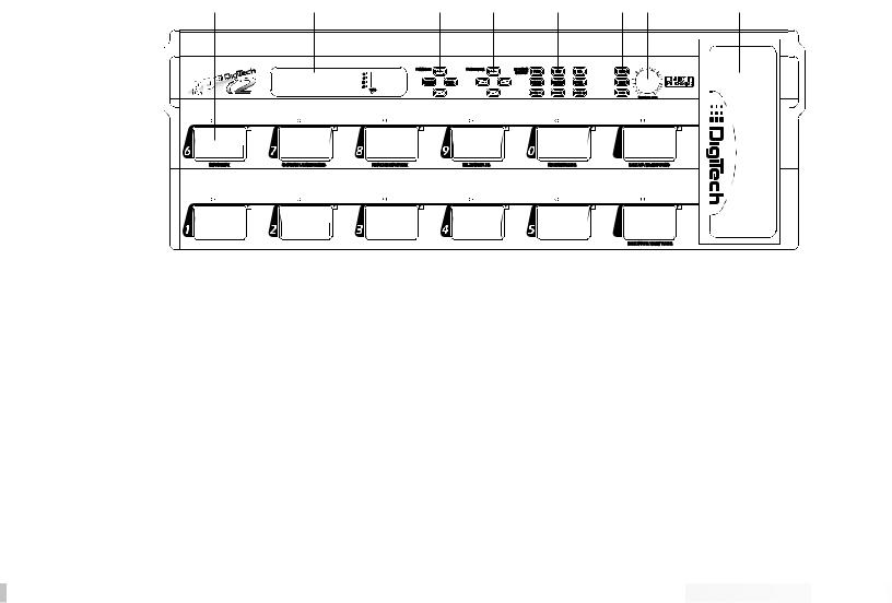
FRONT PANEL CONTROLS The front panel controls and functions of the RP-12 are as follows (refer to diagram):
1 |
2 |
3 |
4 |
5 |
6 |
7 |
8 |
1)Pedalboard - The RP-12’s pedalboard consists of twelve switches and a real-time Continuous Controller Pedal. The ten main switches are labeled 1 - 0 (10) and can be set to turn effects on or off, change Programs, or toggle continuous controllers. From the Factory, switches 1-5 are assigned to change programs. Switches 6-0, are used to turn effects on or off. The Bank Up/Bypass (top row, far right switch) move Up through any of ther 25 banks in the RP-12 and will allow you to bypass all the effect functions of the RP-12 by pressing the footswitch down. When the RP-12 is in Bypass mode, the instrument sound is passed directly from the input to the outputs without effects. The Bank Down/Tuner Switch (bottom row, far right) allows you to move down through any of the 25 banks, by pressing, or access the tuner by pressing and holding the footswitch.


 Section 1 - Startup


8 |
RP-12 Owner’s Manual |
2) Display Window - The display window shows all current operating |
|
and programming information and is comprised of several parts: the |
|
LCD display, the input level meter, the Program number indicator, |
and DSP Clip indicator LEDs. The LCD display shows all Program names, Parameters and Parameter values, and is the communication interface between you and the RP-12. The input level meter monitors the level of the signal entering the digital section. In the Program number indicator window you will find the currently selected Program number. This changes as you scroll through the available Programs. The functions of the Input Level Meter and DSP Clip indicator LEDs are as follows:
• Input Level Meter - Displays the strength of the signal after the preamp section in 6 dB steps, entering the digital section.
• DSP Clip - Indicates digital information overflow in the processor. When lit, distortion may be heard in the output signal. The guideline for this indicator is: let your ears be the judge. If this indicator lights regularly and no audible distortion is present, it can be ignored. If distortion is audible in the output signal, one or more of the internal analog effects levels or the DSP Master level in the Program must be turned down to eliminate the problem.
3) Program Buttons - The Program <UP> and <DOWN> keys allow you to scroll through the RP-12’s effects Programs. The <STORE> key allows you to store a Program in memory for later recall. The <COMPARE> key allows comparison of an edited Program with the original unedited version before it is stored.
4) Parameter Buttons - The Parameter keys perform several different functions. When the Program Title is displayed, the <UP> and <DOWN> Parameter keys do nothing. The <RIGHT> key will move you to the algorithm section, through the modules of the algorithm and into the parameters of the program. The <LEFT> key moves you in the opposite direction (see the diagram on page 12 for further explanation). Once you have accessed the algorithm screen or parameter screen with the <LEFT> and <RIGHT> parameter keys, the <UP> and <DOWN> keys allow you to increase or decrease the displayed values.
5) Effects Library Buttons - This group of buttons allows you to jump directly to the first Parameter of Modules in the currently selected Algorithm. The buttons in this group are: <COMP>, <DIST>, <EQ>, <REVERB>, <DLY/SMP>, <PITCH>, <MOD>, <MIX>, and <MORE>. Also included in this section and sharing buttons with the <MOD>, <MIX>, and <MORE> buttons are the Function keys (indicated by ¡, ™,and £) which act as menu selection keys in the Utility, MIDI, and Naming menus.
6) Global Buttons - These buttons perform global functions. Some of


 Section 1 - Startup


RP-12 Owner’s Manual
these functions include, Utility functions such as LCD contrast,9 Pedalboard , and MIDI setups (including transmit & receive maps). Buttons in this group are: <NAME>, <UTILITY>, and <MIDI>.
7)Main Output Level - This controls the overall output level of the RP-12. It also controls the overall level of the headphones.
8)Continuous Control Pedal - This volume-type pedal allows realtime control over Parameters in the RP-12.
REAR PANEL CONNECTIONS The RP-12 rear panel connectors and functions are as follows:
1 |
2 |
3 |
4 |
5 |
6 |
7 |
|
|
|
|
|||
|
|
|
|
|
|
|
INPUT |
RIGHT |
LEFT/MONO |
HEADPHONES |
POWER |
MIDI |
MIDI |
|
OUTPUT |
OUTPUT |
|
|||
|
|
|
|
9VAC 2.2A |
IN |
OUT/THRU |
|
|
|
|
|
|
|
1)Input - This is the audio input to the RP-12. Plug your instrument in here.
2)Right Output - This is the right main audio output of the RP-12. Use both left and right outputs when Programs are set up to take advantage of stereo effects.
3)Left/Mono Output - This is the left main audio output of the RP-12. Use both left and right outputs when Programs are set up to take advantage of stereo effects. Use either output when the RP-12 is set to mono output.
4)Headphone Output - 1/4” stereo plug for headphones.
5)AC Line Input - This is the power supply receptacle.
6)MIDI In - The MIDI In port allows the RP-12 to respond to incoming MIDI messages, including Program Change, Continuous Control, and System Exclusive data.
7)MIDI Out / Thru - Sends out MIDI data generated by the RP-12 to other devices. It also passes MIDI data transmitted on the RP-12’s MIDI channel through to other devices.


 Section 1 - Startup


RP-12 Owner’s Manual
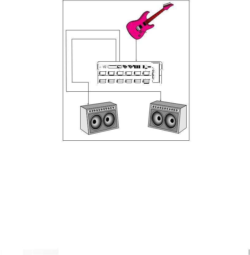
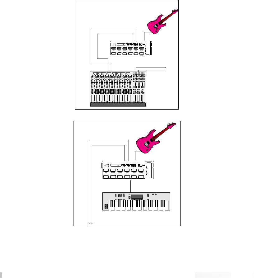
10MIDI AND AUDIO SETUPS The following diagrams show possible MIDI and audio routing setups for the RP-12.
Right |
|
|
Output |
|
|
Left |
|
|
Output |
|
|
|
Input |
|
Guitar |
Guitar |
|
Amp B |
||
Amp A |
||
|
Basic Guitar Setup


 Section 1 - Startup


RP-12 Owner’s Manual |
|
11 |
|
|
|
|
|
Input |
Left |
Right |
To Multitrack and/or Studio Monitors |
Out |
Out |
Mixer Inputs |
|
|
Recording Setup (Use Cabinet Emulator)
|
|
Input |
|
|
MIDI Out |
Left |
Right |
MIDID In |
|
||
Out |
Out |
|
|
|
MIDI Keyboard, Sequencer, or Computer |
o Amplifier(s) |
|
|
Using external MIDI control


 Section 1 - Startup


RP-12 Owner’s Manual
12SECTION 2 - BASIC OPERATIONS
PROGRAM ARCHITECTURE The Program’s Parameter architecture in the RP-12 has been designed to be a linear series of items, rather than a multiple-level menu (see diagram). In other words, instead of including several submenus under a single Parameter heading, all Parameters are included in a single level, and are accessed using the <LEFT> and <RIGHT> Parameter keys. This makes access to specific Parameters of a Program quick and easy, and provides a much clearer picture of exactly where you are in the Program.
a |
|
|
|
|
|
|
|
|
|
|
|
|
|
|
|
|
|
|
|
|
|
|
|
r |
r |
|
|
|
|
|
|
|
|
|
|
|
|
|
|
|
|
|
|
|
|
|
|
|
|
a |
me |
|
|
|
|
|
|
|
|
|
|
|
|
|
|
|
|
|
|
|
|
|
te |
|
|
te |
|
|
|
|
|
|
|
|
|
|
|
|
|
|
|
|
|
|
|
e |
|
||
|
|
r |
|
|
|
|
|
|
|
|
|
|
|
|
|
|
|
|
|
am |
|
|
||
|
|
|
Pa |
|
|
|
|
|
|
|
|
|
|
|
|
|
|
|
ar |
|
|
|
||
|
|
|
|
ra |
me |
|
|
|
|
|
|
|
|
|
|
|
er |
P |
|
|
|
|
||
Item |
|
|
|
It |
ter |
Parameter |
Parameter |
TITLE |
Algorithm |
Parameter |
Param |
|
|
|
Item |
|
||||||||
|
|
|
|
|
|
|
Item |
|
|
|
|
|
|
|
Item |
|
|
|
|
|
|
|
||
|
|
|
|
|
|
em |
|
I |
te |
SCREEN |
|
n |
|
Item |
|
|
|
|
|
|
|
|||
|
|
|
|
|
|
|
|
|
|
m |
|
Selectio |
|
|
|
|
|
|
|
|
|
|
||
|
|
|
PREV |
|
|
PREV |
|
|
|
|
|
|
|
|
|
|
NEXT |
|
|
|
|
|||
|
|
|
|
|
|
|
PREV |
|
|
|
NEXT |
NEXT |
|
|
|
|
|
|||||||
|
|
|
|
|
|
|
|
|
|
|
|
|
|
|
|
|
||||||||
|
|
|
|
|
|
|
|
|
PREV |
|
NEXT |
|
|
|
|
|
|
|
||||||
|
|
|
|
|
|
|
|
|
|
|
|
|
|
|
|
|
|
|
||||||
|
|
|
|
|
|
|
|
|
|
|
|
|
|
|
|
|
|
|
|
|
|
|
||
Linear Parameter Architecture of a Program
The diagram above shows the linear arrangement of the Parameters in the RP-12. Notice that if you press the <RIGHT> Parameter key from the last item in the list (the Parameter item to the left of the title screen), the display jumps, or “wraps around to” the first item in the Program (in this case, the title screen).
Likewise, if the <LEFT> Parameter key is pressed from the title screen, the display will wrap to the last Parameter in the list. This wraparound menu feature is provided so that Parameters that appear near the end of a long list of items can be just as easily reached as items near the beginning of the menu. If you press and hold either the <LEFT> Parameter key or the <RIGHT> Parameter key, the RP-12 will begin scrolling at high speed through the available Parameters.
ACCESSING FACTORY PROGRAMS
There are three methods for recalling factory Programs.
1)The first method uses the <UP> and <DOWN> Program keys. The procedure is as follows:
•From the title screen, press the Program <UP> key. Note that the Program shown in the display changes and the number shown in the LED display increments by one each time the Program <UP> key is pressed. Pressing the Program <DOWN> key causes the opposite to occur: the RP-12 decrements through the Programs in memory.


 Section 2 - Basic Operations


RP-12 Owner’s Manual
• To scroll at high speed through the Programs in13memory, press and hold either the <UP> or <DOWN> Program key.
2) The second method uses the RP-12’s pedalboard. When you change programs using the pedalboard, any unstored modifications you have made to a Program will be lost.
3) The third method is through the use of MIDI. This method will be covered later in the MIDI section of this manual, pg. 58.
TUNING WITH THE RP-12 To access the Tuner using the RP-12 pedalboard, do the following:
•Press and hold the Bank Down/Tuner switch (in the lower right corner of the pedalboard). The display reads:
TUNER A=44O
---- -- --
•Begin tuning your instrument. As you tune, the note name is shown on the top line of the display, while vertical bars appear on the second line of the display and begin strobing. If the note is sharp, the bars will strobe from left to right. If the note is flat, they’ll strobe from right to left. When the note is in tune, the strobing bars will stop moving and asterisks will appear around the note name on the top line of the display.
After a few seconds of tuner inactivity, the display returns to:
TUNER A=44O
---- -- --
•Exit Tuning Mode by pressing any pedal or button.


 Section 2 - Basic Operations


14CHANGING THE TUNING REF You can easily change the RP-12’s tuning reference by using the <UP/DOWN> Parameter buttons while in tuner mode. The top line of the display will show the current setting. The default factory setting is: A=440 Hz. The tuning reference control ranges from 427 Hz to 453 Hz, which is the equivalent of ±50 cents (1/2 semitone) in either direction from 440 Hz.
Scrolling down below# 427 Hz, you can# access the alternative tuning references of: A= G , A=G, and A=F .
When you use any of the alternate tuning as your reference, tune your instrument so that the display shows normal tuning (E, A, D, G, B, & E for guitars) and the RP-12 will do the rest ( the display shows normal tuning, but you’ll actually be tuning to the selected reference).
TUNER A=G
---- -- --
•Exit Tuning Mode by pressing any pedal or button.
ASSIGNING PROGRAMS TO FOOTSWITCHES
The RP-12 has a special function within it’s operating system, that allows you a quick and painless method of assigning any one of the 256 programs in the unit, to any one of the bottom row of footswitches (1-5). For example, you would like to store program 53 (Blue Naked), to footswitch 1. The procedure is as follows:
•From program 53, press and hold the <Utility> function button. The LEDs in the bottom row of footswitches will scroll along the botton row of footswitches, and the display will appear like this:
Select Desired
Foot Switch
•Select and press the desired footswitch, and assignment is made. Now, whenever you press that footswitch, program 53 will be recalled.
For a more in depth explanation on program assignment, please refer to page 49 for more information.
ASSIGNING PARAMETERS TO FOOTSWITCHES
You can easily assign any effect parameter to a Continous Controller by performing a simple linking procedure using the front panel controls of the RP-12. For example, If you wanted to assign Footswitch 7 (CC 22) to control the Compressor On/Bypass Parameter in Program 5 (Wham & Eggs). The procedure is as follows:
• From the Program title screen, scroll to the Compressor


 Section 2 - Basic Operations


RP-12 Owner’s Manual
On/Bypass parameter, by either pressing the Parameter15<right > button five times, or pressing the <COMP> Effects Library Button. Now press and hold the <MIDI> button, and the display reads:
¡Link 5 =NoLink ™Assign
•Press function button <Mix ™> to assign a CC, and the display will appear like this:
Comp On/Bypass |
|
No Link |
³ |
•To assign CC to the parameter, press Footswitch 7, and the display will appear like this:
Comp On/Bypass
Link to:CC 22 ³
•At this point, the Link has been made. Press the function button <MIDI> to exit, and then press store to save the link assignment.
For a more in depth explanation of Assignment of CCs to parameters, please see pg. 50 for more information.


 Section 2 - Basic Operations


RP-12 Owner’s Manual
16SECTION 3 - PROGRAMMING
USING THE FUNCTION BUTTONS The RP-12 has three Function keys. They are located in the bottom row of the Effects Access buttons and they share buttons with the <MOD>, <MIX>, and <MORE> options. Each Function key is numbered and performs several functions in the Utility and MIDI modes (depending on the selected menu screen). These buttons are also used in the Program naming process (see Storing/Naming on page 19). See pg. 49 for more on the Utility Button. See pg. 58 for more on the MIDI Button.
¡™& £ are used in the display to indicate which function key to use.
MORE SPECIAL CHARACTERS There are several special characters that the RP-12 uses to tell you at a glance exactly what it is doing. Some special characters in the RP-12 are in inverted type, that is, reversed out of a black background, and they will usually appear in the upper right-hand corner of the Program Title screen.
ßIndicates that the Cabinet Emulator is currently active.
Ç Indicates that a MIDI continuous controller is linked to the Parameter.
åºCharacters from this group are used for distinguishing between Modules of the same name in a single Algorithm. This is an instance in which a special character will immediately follow the Module name, rather than appear in the corner of the display.
*Indicates a Program has been modified.
( ) Indicates the value within the brackets is a stored or saved value.


 Section 3 - Programming


THE EFFECTS LIBRARY BUTTONS 17
The Effects Library buttons are used to jump to specific places in a Program. For example, if a Program contains two choruses and you want to change the delay time on only one of them, you could press the <MOD> Effects Library button from Program Title screen and you would jump to the first Parameter of the first chorus in the Algorithm. Press the button again, and you are taken to the first Parameter of the next chorus in the Algorithm.
ABOUT THE I /O MODULE Each Program in the RP-12 is equipped with Compression, Distortion, Clean / Distortion Level, Noise Gate, DSP Master Level, Parametric EQ, Wet/Dry Mix, and Cabinet Emulator controls. These items are permanent residents of every Algorithm in the unit.
This group of items is called the Input / Output Module (or I/O Module) because they are always a part of both the input and output audio paths of the RP-12. The following diagram shows how the I/O Module affects the signal as it flows through the unit.
|
|
Bypass Switch |
|
I / O |
Algorithm |
From Inst. |
Module |
(Digital Section) |
|
|
To Outputs |
Compression (A) |
Reverb |
Master Mix (D) |
Distortion (A) |
Delay / Sampler |
|
Clean / Dist Level (A) |
Modulation |
|
Noise Gate (D) |
Pitch Shift |
|
DSP Master Level (D) |
Mixers |
|
Parametric EQ (D) |
Etc... |
A = Analog |
Cabinet Emulator (D) |
|
|
|
D = Digital |
|
|
|
The RP-12’s Compression, Distortion, and Clean / Distortion Level are analog for warmth and power. The Noise Gate, DSP Master Level, Parametric EQ, Wet/Dry Mix and Cabinet Emulator are all accomplished in the digital section, for absolute flexibility and precision.
MODIFYING FACTORY PROGRAMS
After you’ve had time to familiarize yourself with the RP-12, you may find that there are several factory Programs that are very close to what you’re looking for, but need a few small tweaks to get them perfect. Program 2 (Clean and Tight) has a chorus and delay. Let’s assume that in order to work in your application, it needs to have a 60Hz cho-


 Section 3 - Programming


18 |
|
|
RP-12 Owner’s Manual |
|
rus speed. Using this Program as an example for Program modifica- |
||||
|
||||
|
tion, the procedure for changing the Chorus Speed is as follows: |
|||
|
|
• From the Program title screen, scroll to Program 2 using the |
||
|
|
<UP/DOWN> Program buttons. The display reads: |
||
|
|
|
||
|
|
Clean and Tight |
|
|
|
|
DCho³2TDly³2Pans |
|
|
|
|
|
|
|
|
|
• Using the <RIGHT> and <LEFT> Parameter buttons, scroll to the |
||
|
|
CHORUS SPEED Parameter. |
||
|
The display reads: |
|||
|
|
|
||
|
|
Chorus Speed |
|
|
|
|
(0.28Hz) |
|
|
|
|
|
|
|
|
|
NOTE: By pressing the <MOD> key you can skip directly to the |
||
|
|
first Parameter of the Chorus effect within the Algorithm, then con- |
||
|
|
tinue scrolling with the <RIGHT> Parameter key to the Chorus |
||
|
|
Speed parameter. |
||
|
|
• Using the <UP> Parameter key, scroll upward until you reach |
||
|
|
0.60Hz. The display reads: |
||
|
|
|
|
|
|
|
Chorus Speed |
|
|
|
|
0.60Hz |
|
|
|
|
|
|
|
|
If you change Programs at this point (either through MIDI, the pedal- |
|||
|
board, or the Program buttons), any modifications that you have made |
|||
|
to the Program will be lost. In order for the RP-12 to remember the |
|||
|
changes that you have made, you must store the Program in memory. |
|||
|
The procedure for storing Programs is covered in more detail on pg 20. |
|||
BASIC PROGRAM CREATION |
There are three requirements for creating a Program on the RP-12. |
|||
|
The first is that an Algorithm needs to be assigned to the Program; |
|||
|
second, Parameters must be modified to your liking, and third, the |
|||
|
Program must be stored in memory in order to be recalled for later |
|||
|
use. |
|||
SELECTING AN ALGORITHM |
The Algorithm you choose for a Program determines the basic function |
|||
|
of the Program. It is therefore necessary to choose an Algorithm that |
|||
|
contains all the Modules you want to use in an appropriate configura- |
|||
|
tion (for a complete listing of the RP-12’s algorithms, see page 67). |
|||
|
The Algorithm selection screen for all Programs in the RP-12 is one |
|||
|
screen to the right of the title screen. |
|||
|
NOTE: It may be easiest to select a Program that uses the Algorithm |
|||


 Section 3 - Programming


RP-12 Owner’s Manual 19
The Algorithm selection screen works in conjunction with the LED display to show the currently selected Algorithm number. When in the Algorithm selection screen, the LCD display looks something like this:
ALGORITHM NAME--> Wham³2TDly³Revrb
Comp Dist MVol³ <-- EFFECTS ROUTING WITHIN ALGORITHM
To select an Algorithm for a Program, the procedure is as follows:
• From the title screen, press the <RIGHT> Parameter key once. This is the Algorithm selection screen. The name of the currently selected Algorithm is shown on the top line of the display, while the bottom line shows the effects in the Algorithm.
NOTE: When there are more effects in the Algorithm than will fit on a single line of the display, an arrow will appear in the first and/or last character of the bottom line of the display. These arrows indicate that there is more information about the effects that could not be displayed on a single screen. To see the remaining information, simply press the <RIGHT> or <LEFT> Parameter key (depending on the arrow direction indicated in the display).
• Use the <UP> and <DOWN> Parameter buttons to select the Algorithm you want to use with the Program. The LED display now shows the Algorithm number as you scroll up or down.
• Use the<RIGHT> and <LEFT> Parameter buttons to begin modifying the Parameters of the currently selected Algorithm to suit your purpose.
NOTE: When you change the currently selected Algorithm, the default Parameters selected for the new Algorithm are taken from the first Factory Program in memory that uses that Algorithm.
|
Once you have selected the Algorithm you want to use and modified |
|
its Parameters, an asterisk appears in the upper right corner of the title |
|
screen. This asterisk indicates that the Program has been modified |
|
and any changes you have made will be lost if not stored in the RP- |
|
12’s memory. |
NAMING PROGRAMS |
In order for modified Programs to be available for later recall, you must |
|
store them in memory. This is accomplished using the <STORE> key. |
|
The RP-12 also allows you to give your Programs custom names up to |
|
15 characters in length. This is accomplished using the <NAME> key. |
|
The naming procedure uses the <UP> and <DOWN> Parameter but- |
|
tons, and the Function buttons ¡ ™ & £ to change the letters of the |
|
alphabet. The <MOD ¡> key changes the character from either upper |
|
or lower case, and jumps you to the letters of the character set. The |


 Section 3 - Programming


20 |
|
|
RP-12 Owner’s Manual |
<MIX ™> key puts a space into the Program name, and jumps you to |
|||
the special characters in the character set. The <MORE £> key inserts |
|||
an ‘0’, and jumps you to the numbers section of the character set. The |
|||
complete procedure for naming and storing a Program is as follows: |
|||
|
|
• After you have made all the necessary modifications to the |
|
|
|
Algorithm, press the <NAME> button once. The RP-12 is now in |
|
|
|
Name mode. The display shows: |
|
|
|
|
|
|
|
[PROGRAM NAME] |
|
|
|
¡CAPS ™SPC £NUM |
|
|
|
|
|
|
The blocked numbers preceding each option on the bottom line indi- |
||
|
cate the Function key that will perform the function shown. |
||
|
|
• Using the <UP/DOWN> Parameter buttons, scroll to the charac- |
|
|
|
ter you want to use, or press one of the Function buttons. When |
|
|
|
you have selected the character you want, press the <RIGHT> |
|
|
|
Parameter key. Note that the cursor moves to the next character. |
|
|
|
Repeat this procedure until the Program name is satisfactory. |
|
|
Unique to the RP-12 naming process, are several special naming func- |
||
|
tions. The <COMPARE> and <STORE> buttons allow you to bump an |
||
|
entire name or section of a name either left or right in one-space incre- |
||
|
ments. The procedure is as follows: |
||
|
|
• In Name mode, use the <RIGHT> and <LEFT> Parameter but- |
|
|
|
tons to place the cursor underneath the character to be moved. |
|
|
|
• Press the <COMPARE> or <STORE> buttons to move the char- |
|
|
|
acters either left or right. |
|
|
The Program <UP> key copies the character the cursor is under into |
||
|
memory. This allows you to place a copy of that character (using the |
||
|
Program <DOWN> key) anywhere else in the name that you want. |
||
|
The procedure is as follows: |
||
|
|
• In Name mode, use the <RIGHT/LEFT> Parameter buttons to |
|
|
|
place the cursor under the character to be copied. |
|
|
|
• Press the Program <UP> key. The selected character is copied |
|
|
|
into memory. |
|
|
|
• Move the cursor to the location into which you want to place a |
|
|
|
copy of the character and press the Program <DOWN> key. The |
|
|
|
copy appears in the location you selected. |
|
|
|
NOTE: Press the <UTILITY> button to abort the operation. When |
|
|
|
you change programs the original name will return. |
|


 Section 3 - Programming


RP-12 Owner’s Manual
• When the Program name appears as you want it, press the
|
|
<NAME> button to exit the name selection mode. |
||
STORING PROGRAMS |
Once you have dialed in the program how you want |
given it a |
||
21it and |
||||
|
name, press the <STORE> button. The display reads: |
|||
|
|
|
|
|
|
|
Store To Prg ## |
|
|
|
|
[PROGRAM NAME] |
|
|
|
|
|
|
|
|
This screen allows you to select the Program location in which you |
|||
|
want to store the new Program. |
|
||
•Using the <UP> and <DOWN> Program buttons, scroll to the Program number location in which you want to store the new Program.
•To store the Program in the selected location, press the <STORE> key again. The display briefly reads:
***Storing***
after which you will automatically be returned to the previous mode. To abort the command, press <COMPARE>.
The Store function can also be used to copy Programs from one memory location to another. If no changes have been made to the selected Program and the <STORE> button is pressed, the display reads:
Copy To Prg ## [PROGRAM NAME]
Select the memory location in which you want to place a copy of the selected Program using the <UP> and <DOWN> Program buttons, and press <STORE> again. The display briefly reads:
***Copying***
after which you will automatically be returned to the previous mode. To abort the command and return to the Program, press the <COMPARE> button.


 Section 3 - Programming


RP-12 Owner’s Manual
SECTION 4 - EFFECTS AND PARAMETERS
BOUT THE EFFECTS LIBRARY The Effects Library consists of all the effects Modules you can find in |
||||||
22A |
the RP-12. Broken down into individual categories, specific Modules |
|||||
|
|
|
and their abbreviated library names are as follows: |
|||
|
Analog Effects |
|
|
|
|
|
|
|
|
|
|
|
|
|
Module Name |
|
Module Abbrv. |
Description |
|
|
|
Compressor |
|
Comp |
Analog compressor tailored for instruments |
|
|
|
|
|
|
|
|
|
|
Distortion |
|
Dist |
Analog distortion (3 solid-state types) |
|
|
|
|
|
|
|
|
|
|
|
|
The analog section of the RP-12 includes the compressor and the dis- |
|||
|
|
|
tortion section. These two items are always available in all Programs. |
|||
|
|
|
The analog effects and their Parameters are as follows: |
|||
COMPRESSOR |
The RP-12’s compressor is a high-quality, low-noise circuit specially |
|||||
|
|
|
designed for guitars. Compression can be used to increase sustain |
|||
|
|
|
and to tighten up guitars, and is particularly useful on clean sounds. |
|||
|
|
|
Parameters of the RP-12 compressor are as follows: |
|||
|
|
|
Comp On / Bypass........Turns the Module on or off. When Modules are |
|||
|
|
|
|
|
bypassed their Parameters disappear from the |
|
|
|
|
|
|
Parameter menu. To see the Parameters, you |
|
|
|
|
|
|
must turn the Module on. |
|
|
|
|
Comp Amount ...............Controls the amount of compression applied to |
|||
|
|
|
|
|
the signal. Higher settings yield a tighter, more |
|
|
|
|
|
|
focused sound, while lower settings allow bet- |
|
|
|
|
|
|
ter dynamics. Ranges from 0 to 31. |
|
|
|
|
Comp Level ...................Sets the output level of the compressor before |
|||
|
|
|
|
|
feeding to the distortion. Higher settings send |
|
|
|
|
|
|
more signal level into the distortion, yielding |
|
|
|
|
|
|
extra gain and drive. Varies from 1 to 7. |
|
DISTORTION |
The distortion section of the RP-12 is capable of producing three dis- |
|||||
|
|
|
tinctly different types of distortion. These three solid-state distortion |
|||
|
|
|
sounds range from lightly overdriven, to screaming grunge. The |
|||
|
|
|
Grunge setting gives you extremely high-gain distortion, free from the |
|||
|
|
|
mush and tonal sacrifices typical of other manufacturers’ products. |
|||
|
|
|
Dist On / Bypass ........... |
Turns the Module on or off. When Modules are |
||
|
|
|
|
|
turned off, their Parameters disappear from the |
|
|
|
|
|
|
Parameter menu. To see the Parameters, you |
|
|
|
|
|
|
must turn the Module on. |
|
|
|
|
Distortion Type .............. |
Selects the type of distortion to be used in the |
||


 Section 4 - Effects and Parameters


RP-12 Owner’s Manual
Program. Options are: OVERDRIVE23- Solidstate overdrive with extra punch. HEAVY SUSTAIN - Smooth, warm distortion sound with lots of sustain. GRUNGEHigh gain distortion which is tight and highly focused for powerful rhythms and leads.
Distortion Gain ..............Controls the amount of distortion produced by the RP-12. High settings produce greater gain and drive for effortless soloing, while low settings offer better nuance and touch control.
Ranges from 0 to 11.0.
Dist/Clean Level ............This Parameter allows two separate levels to be set. If the Distortion is turned on, the Distortion level can be adjusted. If the Distortion is turned off, the Clean level can be adjusted. Both level settings are saved when the Program is stored. Settings include MUTE or ranging from -60dB to +12dB.
Equalizers
Module Name |
Module Abbrv. |
Description |
|
|
|
10 Band GEQ |
GEQ10 |
Full bandwidth 10-band graphic equalizer |
|
|
|
4Bnd ParamtrcEQ |
PEQ4 |
4-band parametric equalizer w/adjustable Q |
|
|
|
Cabinet Emulator |
CabEm |
Full-bore stack sound direct-to-console |
|
|
|
The equalizer Modules provided in the RP-12 offer superb noise performance, and allow accurate tonal shaping of many different types of sound sources. A 4-band parametric equalizer with adjustable Q is available in all Algorithms. The RP-12 also features a 10-band Graphic Equalizer module. All equalizer Modules offer silent, accurate (doubleprecision) tonal shaping.
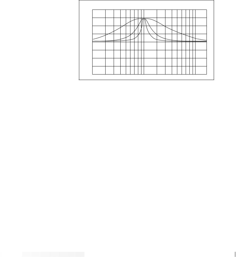
Adjustable Q equalizers offer the ability to control the bandwidth of the boost/cut ranges. High Q settings yield extremely narrow bandwidth, where boost and cut have minimal effect on adjacent frequencies of the program material. Low Q settings affect a wider number of frequencies when the selected band is boosted or cut.


 Section 4 - Effects and Parameters


24
CABINET EMULATOR
RP-12 Owner’s Manual
DigiTech Audio Precision STD AMPL (dBr) vs FREQ (Hz)
20.000
15.000
10.000
5.0000
0.0
-5.000
-10.00
-15.00
-20.00
100
2 |
|
= |
4 |
Q |
|
|
= |
|
Q |
8 = Q
1k |
10k |
With a Q setting of 2, you can see that a large number of frequencies are affected by boosting the center frequency. Now take a look at the middle and lower curves in the diagram, and notice the much narrower bandwidth of the curves with a Q setting of 4 and 8.
The RP-12’s programmable Cabinet Emulator circuitry allows you to use it in both recording and live situations, without lugging heavy amps and/or cabinets around. Just connect the RP-12 outputs to a mixing console, and kick in the Cabinet Emulator. No miking hassles, no heavy equipment, just full on mic’d cabinet sound. Programs can be stored with different Cabinet Emulator settings so you can customize your banks or set lists for whatever sound types you need. The Cabinet Emulator can be controlled globally from the <UTILITY> Menu. Parameters are as follows:
Cabinet On / Bypass .....Turns the Module on or off. When Modules are turned off, their Parameters disappear from the Parameter menu. To see the Parameters, you must turn the Module on.
Cabinet Type.................Selects the tonal characteristics of the simulated cabinet. There are 10 different cabinet types; 3 warm cabinets, 3 medium cabinets, 3 bright cabinets, and 1 full bandwidth cabinet for maximum frequency response. The full bandwidth cabinet is useful when the global Cabinet Emulator is active (in the Utility menu), and a full bandwidth sound is still desired.


 Section 4 - Effects and Parameters


 Loading...