


IMPORTANT SAFETY INSTRUCTIONS
The symbols shown above are internationally accepted symbols that warn of potential hazards with electrical products. The lightning flash with arrowpoint in an equilateral triangle means that there are dangerous voltages present within the unit. The exclamation point in an equilateral triangle indicates that it is necessary for the user to refer to the owner’s manual.
These symbols warn that there are no user serviceable parts inside the unit. Do not open the unit. Do not attempt to service the unit yourself. Refer all servicing to qualified personnel. Opening the chassis for any reason will void the manufacturer’s warranty. Do not get the unit wet. If liquid is spilled on the unit, shut it off immediately and take it to a dealer for service. Disconnect the unit during storms to prevent damage.
SAFETY INSTRUCTIONS
NOTICE FOR CUSTOMERS IF YOUR UNIT IS EQUIPPED WITH A POWER CORD.
WARNING: THIS APPLIANCE MUST BE EARTHED.
The cores in the mains lead are coloured in accordance with the following code:
GREEN andYELLOW - Earth BLUE - Neutral BROWN - Live
As colours of the cores in the mains lead of this appliance may not correspond with the coloured markings identifying the terminals in your plug, proceed as follows:
•The core which is coloured green and yellow must be connected to the terminal in the plug marked with the letter E, or with the earth symbol, or coloured green, or green and yellow.
•The core which is coloured blue must be connected to the terminal marked N or coloured black.
•The core which is coloured brown must be connected to the terminal marked L or coloured red.
This equipment may require the use of a different line cord, attachment plug, or both, depending on the available power source at installation. If the attachment plug needs to be changed, refer servicing to qualified service personnel who should refer to the table below. The green/yellow wire shall be connected directly to the units chassis.
CONDUCTOR |
WIRE COLOR |
|||
Normal |
Alt |
|||
|
|
|||
L |
LIVE |
BROWN |
BLACK |
|
N |
NEUTRAL |
BLUE |
WHITE |
|
E |
EARTH GND |
GREEN/YEL |
GREEN |
|
WARNING: If the ground is defeated, certain fault conditions in the unit or in the system to which it is connected can result in full line voltage between chassis and earth ground. Severe injury or death can then result if the chassis and earth ground are touched simultaneously.
WARNING FOR YOUR PROTECTION PLEASE READ THE FOLLOWING:
KEEP THESE INSTRUCTIONS
HEED ALL WARNINGS
FOLLOW ALL INSTRUCTIONS
DO NOT USE THIS APPARATUS NEAR WATER
CLEAN ONLY WITH A DRY CLOTH.
DO NOT BLOCK ANY OF THE VENTILATION OPENINGS. INSTALL IN ACCORDANCE WITH THE MANUFACTURER’S INSTRUCTIONS.
DO NOT INSTALL NEAR ANY HEAT SOURCES SUCH AS RADIATORS, HEAT REGISTERS, STOVES, OR OTHER APPARATUS (INCLUDING AMPLIFIERS) THAT PRODUCE HEAT.
ONLY USE ATTACHMENTS/ACCESSORIES SPECIFIED BY THE MANUFACTURER.
UNPLUG THIS APPARATUS DURING LIGHTNING STORMS OR WHEN UNUSED FOR LONG PERIODS OF TIME.
Do not defeat the safety purpose of the polarized or grounding-type plug. A polarized plug has two blades with one wider than the other. A grounding type plug has two blades and a third grounding prong. The wide blade or third prong are provided for your safety. If the provided plug does not fit your outlet, consult an electrician for replacement of the obsolete outlet.
Protect the power cord from being walked on or pinched particularly at plugs, convenience receptacles, and the point where they exit from the apparatus.
Use only with the cart stand, tripod bracket, or table specified by the manufacture, or sold with the apparatus. When a cart is used, use caution when moving the cart/apparatus combination to avoid injury from tip-over.
Refer all servicing to to qualified service personnel. Servicing is required when the apparatus has been damaged in any way, such as power-supply cord or plug is damaged, liquid has been spilled or objects have fallen into the apparatus, the apparatus has been exposed to rain or moisture, does not operate normally, or has been dropped.
POWER ON/OFF SWITCH: For products provided with a power switch, the power switch DOES NOT break the connection from the mains.
MAINS DISCONNECT: The plug shall remain readily operable. For rack-mount or installation where plug is not accessible, an all-pole mains switch with a contact separation of at least 3 mm in each pole shall be incorporated into the electrical installation of the rack or building.
FOR UNITS EQUIPPED WITH EXTERNALLY ACCESSIBLE FUSE RECEPTACLE: Replace fuse with same type and rating only.
MULTIPLE-INPUT VOLTAGE:This equipment may require the use of a different line cord, attachment plug, or both, depending on the available power source at installation. Connect this equipment only to the power source indicated on the equipment rear panel.To reduce the risk of fire or electric shock, refer servicing to qualified service personnel or equivalent.
This Equipment is intended for rack mount use only.
IMPORTANT SAFETY INSTRUCTIONS
LITHIUM BATTERY WARNING
CAUTION!
This product may contain a lithium battery.There is danger of explosion if the battery is incorrectly replaced. Replace only with an Eveready CR 2032 or equivalent. Make sure the battery is installed with the correct polarity. Discard used batteries according to manufacturer’s instructions.
ADVARSEL!
Lithiumbatteri - Eksplosjonsfare.Ved utskifting benyttes kun batteri som anbefalt av apparatfabrikanten. Brukt batteri returneres apparatleverandøren.
ADVARSEL!
Lithiumbatteri - Eksplosionsfare ved fejlagtig håndtering. Udskiftning må kun ske med batteri av samme fabrikat og type. Levér det brugte batteri tilbage til leverandøren.
VAROITUS!
Paristo voi räjähtää, jos se on virheellisesti asennettu. Vaihda paristo ainoastaan laitevalmistajan suosittelemaan tyyppin. Hävitä käytetty paristo valmistajan ohjeiden mukaisesti.
VARNING!
Explosionsfara vid felaktigt batteribyte. Använd samma batterityp eller en ekvivalent typ som rekommenderas av apparattillverkaren. Kassera använt batteri enligt fabrikantens instruktion.
ELECTROMAGNETIC
COMPATIBILITY
This unit conforms to the Product Specifications noted on the Declaration of Conformity. Operation is subject to the following two conditions:
•this device may not cause harmful interference, and
•this device must accept any interference received, including interference that may cause undesired operation.
Operation of this unit within significant electromagnetic fields should be avoided.
•use only shielded interconnecting cables.
U.K. MAINS PLUG WARNING
A molded mains plug that has been cut off from the cord is unsafe. Discard the mains plug at a suitable disposal facility. NEVER UNDER ANY CIRCUMSTANCES SHOULD YOU INSERT A DAMAGED OR CUT MAINS PLUG INTO A 13 AMP POWER SOCKET. Do not use the mains plug without the fuse cover in place. Replacement fuse covers can be obtained from your local retailer. Replacement fuses are 13 amps and MUST be ASTA approved to BS1362.
DECLARATION OF
CONFORMITY
Manufacturer’s Name: |
DigiTech |
Manufacturer’s Address: |
8760 S. Sandy Parkway |
|
Sandy, Utah 84070, USA |
declares that the product: |
|
Product name: |
GNX4 |
Note: Product name may be suffixed by the letters EU, JA, NP and UK.
Product option: |
all (requires Class II power |
|
adapter that conforms to the |
|
requirements of EN60065, |
|
EN60742, or equivalent.) |
conforms to the following Product Specifications: |
|
Safety: |
IEC 60065 (1998) |
EMC: |
EN 55013 (1990) |
|
EN 55020 (1991) |
Supplementary Information:
The product herewith complies with the requirements of the Low Voltage Directive 72/23/EEC and the EMC Directive 89/336/EEC as amended by Directive 93/68/EEC.
|
Vice-President of Engineering |
|
8760 S. Sandy Parkway |
|
Sandy, Utah 84070, USA |
|
Date: March 15, 2004 |
European Contact: |
Your local DigiTech Sales and |
Service Office or |
|
|
Harman Music Group |
|
8760 South Sandy Parkway |
|
Sandy, Utah 84070 USA |
|
Ph: (801) 566-8800 |
|
Fax: (801) 568-7583 |
Warranty
We at DigiTech are very proud of our products and back-up each one we sell with the following warranty:
1.The warranty registration card must be mailed within ten days after purchase date to validate this warranty.
2.DigiTech warrants this product, when used solely within the U.S., to be free from defects in materials and workmanship under normal use and service.
3.DigiTech liability under this warranty is limited to repairing or replacing defective materials that show evidence of defect, provided the product is returned to DigiTech WITH RETURN AUTHORIZATION, where all parts and labor will be covered up to a period of one year. A Return Authorization number may be obtained from DigiTech by telephone.The company shall not be liable for any consequential damage as a result of the product's use in any circuit or assembly.
4.Proof-of-purchase is considered to be the burden of the consumer.
5.DigiTech reserves the right to make changes in design, or make additions to, or improvements upon this product without incurring any obligation to install the same on products previously manufactured.
6.The consumer forfeits the benefits of this warranty if the product's main assembly is opened and tampered with by anyone other than a certified DigiTech technician or, if the product is used with AC voltages outside of the range suggested by the
manufacturer.
7.The foregoing is in lieu of all other warranties, expressed or implied, and DigiTech neither assumes nor authorizes any person to assume any obligation or liability in connection with the sale of this product. In no event shall DigiTech or its dealers be liable for special or consequential damages or from any delay in the performance of this warranty due to causes beyond their control.
NOTE: The information contained in this manual is subject to change at any time without notification. Some information contained in this manual may also be inaccurate due to undocumented changes in the product or operating system since this version of the manual was completed.The information contained in this version of the owner's manual supersedes all previous versions.
Introduction . . . . . . . . . . . . . . . . . . . . . . |
. . . . .1 |
Included Items . . . . . . . . . . . . . . . . . . . . . . . . |
. . . . .1 |
Quick Start . . . . . . . . . . . . . . . . . . . . . . . . . . . |
. . . .2 |
Make Connections . . . . . . . . . . . . . . . . . . . . |
. . . .2 |
Speaker Compensation . . . . . . . . . . . . . . . . |
. . . .2 |
Apply Power . . . . . . . . . . . . . . . . . . . . . . . . |
. . . .2 |
Select an Output Setup Mode . . . . . . . . . . . |
. . . .2 |
Select a Preset . . . . . . . . . . . . . . . . . . . . . . . |
. . . .2 |
A Guided Tour of the GNX4 . . . . . . . . . . . . . |
. . . .3 |
The Front Panel . . . . . . . . . . . . . . . . . . . . . . |
. . . .3 |
The Rear Panel . . . . . . . . . . . . . . . . . . . . . . |
. . . .6 |
Audio Routing Setups . . . . . . . . . . . . . . . . |
. . . .9 |
Setups Introduction . . . . . . . . . . . . . . . . . . . . . |
. . . .9 |
Output Setups and Speaker Compensation |
. . . . .9 |
Mic and Line Setups . . . . . . . . . . . . . . . . . . . |
. . . .12 |
Optimizing the Mic Input Level . . . . . . . . . . |
. . . .13 |
Optimizing the Line Input Levels . . . . . . . . . |
. . . .13 |
Making Connections . . . . . . . . . . . . . . . . . |
. . . .14 |
For Live Performance . . . . . . . . . . . . . . . . . . . |
. . . .14 |
Small Club Setup (Mono Amp Rig) . . . . . . . . |
. . . .14 |
Medium Stage Setup (Stereo Amp Rig) . . . . |
. . . .14 |
Large Stage Setup (Stereo Amp/Cabinet Rig) |
. . . .15 |
Talker™ Performance Setup . . . . . . . . . . . . . . |
. . . .16 |
Coffee House/Solo Performance Setup . . . . |
. . . .17 |
For Recording . . . . . . . . . . . . . . . . . . . . . . . . . |
. . . .18 |
Onboard Recorder Application . . . . . . . . . . |
. . . .18 |
Computer Recording Application . . . . . . . . . |
. . . .19 |
Applying Power . . . . . . . . . . . . . . . . . . . . . . . |
. . . .20 |
About the GNX4 . . . . . . . . . . . . . . . . . . . . |
. . . .21 |
Presets . . . . . . . . . . . . . . . . . . . . . . . . . . . . . . |
. . . .21 |
Footswitch Modes . . . . . . . . . . . . . . . . . . . . . . |
. . . .21 |
Preset Mode . . . . . . . . . . . . . . . . . . . . . . . . |
. . . .21 |
Preset Bounceback . . . . . . . . . . . . . . . . . . |
. . . .22 |
Stompbox/Control Mode . . . . . . . . . . . . . . . |
. . . .22 |
Recorder Mode . . . . . . . . . . . . . . . . . . . . . . |
. . . .22 |
Expression Pedal . . . . . . . . . . . . . . . . . . . . . . |
. . . .22 |
Bypass . . . . . . . . . . . . . . . . . . . . . . . . . . . . . . . |
. . . .23 |
Tuner . . . . . . . . . . . . . . . . . . . . . . . . . . . . . . . |
. . . .23 |
GNX4 Matrix Functions . . . . . . . . . . . . . . |
. . . .24 |
The GNX4 Matrix . . . . . . . . . . . . . . . . . . . . . |
. . . .24 |
Viewing/Editing GeNetX™ and |
|
Amp Parameter Values . . . . . . . . . . . . . . . . . . |
. . . .24 |
Viewing/Editing Effect Parameter Values . . . . . . |
. . . .25 |
GENETX Row . . . . . . . . . . . . . . . . . . . . . . . . |
. . . .26 |
CHAN ONE EQ and CHAN TWO EQ Rows |
. . . .27 |
TONE Row . . . . . . . . . . . . . . . . . . . . . . . . . . . |
. . . .29 |
Amp/Cabinet Modeling . . . . . . . . . . . . . . . |
. . . .30 |
Amp Models . . . . . . . . . . . . . . . . . . . . . . . . |
. . . .30 |
Cabinet Types . . . . . . . . . . . . . . . . . . . . . . . |
. . . .31 |
Editing Amp Models and Cabinet Types . . . . . . |
. . . .31 |
Selecting Amp Models and Cabinet Types . . . |
. . . .32 |
Adjusting Amp Parameters . . . . . . . . . . . . . . |
. . . .32 |
Cabinet Tuning . . . . . . . . . . . . . . . . . . . . . . . |
. . . .32 |
Storing Amp Parameter Edits . . . . . . . . . . . . |
. . . .33 |
Table of Contents
Creating HyperModels™ . . . . . . . . . . . . . . . . . . . . .33
Saving HyperModels (Amp Save) . . . . . . . . . . . . . . .33
Effects and Parameters . . . . . . . . . . . . . . |
. . . . .34 |
Editing a Preset’s Effects . . . . . . . . . . . . . . . . |
. . . . .34 |
Effect Definitions . . . . . . . . . . . . . . . . . . . . . . . |
. . . .35 |
Preset Levels . . . . . . . . . . . . . . . . . . . . . . . . . . |
. . . .35 |
Wah-Pickup . . . . . . . . . . . . . . . . . . . . . . . . . |
. . . .35 |
Compressor . . . . . . . . . . . . . . . . . . . . . . . . |
. . . .35 |
Whammy™/IPS/Talk . . . . . . . . . . . . . . . . . . . |
. . . .36 |
Whammy . . . . . . . . . . . . . . . . . . . . . . . . |
. . . .36 |
Intelligent Pitch Shifting (IPS) . . . . . . . . . . |
. . . .37 |
Detune . . . . . . . . . . . . . . . . . . . . . . . . . . |
. . . .37 |
Pitch Shift . . . . . . . . . . . . . . . . . . . . . . . . . |
. . . .37 |
Talker™ . . . . . . . . . . . . . . . . . . . . . . . . . . . |
. . . .37 |
Stomp Box Modeling . . . . . . . . . . . . . . . . . . |
. . . .38 |
Noise Gate . . . . . . . . . . . . . . . . . . . . . . . . . |
. . . .39 |
Chorus/Mod Effects . . . . . . . . . . . . . . . . . . . |
. . . .39 |
Chorus . . . . . . . . . . . . . . . . . . . . . . . . . . . |
. . . .39 |
Flanger . . . . . . . . . . . . . . . . . . . . . . . . . . . |
. . . .40 |
Phaser . . . . . . . . . . . . . . . . . . . . . . . . . . . |
. . . .40 |
Triggered Flanger . . . . . . . . . . . . . . . . . . . |
. . . .40 |
Triggered Phaser . . . . . . . . . . . . . . . . . . . . |
. . . .40 |
Tremolo . . . . . . . . . . . . . . . . . . . . . . . . . . |
. . . .41 |
Panner . . . . . . . . . . . . . . . . . . . . . . . . . . . |
. . . .41 |
Vibrato . . . . . . . . . . . . . . . . . . . . . . . . . . . |
. . . .41 |
Rotary Speaker . . . . . . . . . . . . . . . . . . . . . |
. . . .41 |
AutoYa™ . . . . . . . . . . . . . . . . . . . . . . . . . . |
. . . .42 |
YaYa™ . . . . . . . . . . . . . . . . . . . . . . . . . . . . |
. . . .42 |
SynthTalk™ . . . . . . . . . . . . . . . . . . . . . . . . |
. . . .42 |
Envelope Filter . . . . . . . . . . . . . . . . . . . . . |
. . . .42 |
Detune . . . . . . . . . . . . . . . . . . . . . . . . . . . |
. . . .43 |
Pitch Shift . . . . . . . . . . . . . . . . . . . . . . . . . |
. . . .43 |
Delay . . . . . . . . . . . . . . . . . . . . . . . . . . . . . . |
. . . .43 |
Reverb . . . . . . . . . . . . . . . . . . . . . . . . . . . . |
. . . .44 |
Expression Pedal Assignment . . . . . . . . . . |
. . . .45 |
Expression Pedal . . . . . . . . . . . . . . . . . . . . . |
. . . .45 |
Expression Pedal Links 1-3 . . . . . . . . . . . . . . |
. . . .45 |
Wah Pedal . . . . . . . . . . . . . . . . . . . . . . . . . |
. . . .45 |
Amp Channel Footswitch . . . . . . . . . . . . . . |
. . . .46 |
Control Footswitches . . . . . . . . . . . . . . . . . |
. . . .46 |
Control A, B, and C Links . . . . . . . . . . . . . . |
. . . .46 |
LFOs . . . . . . . . . . . . . . . . . . . . . . . . . . . . . |
. . . .47 |
LFO Links 1-2 . . . . . . . . . . . . . . . . . . . . . . . |
. . . .47 |
Expression Parameter Assignment List . . . . . |
. . . .48 |
Whammy™/IPS/Talker™ Effect Parameters |
. . . . .48 |
Stompbox Effect Parameters . . . . . . . . . . |
. . . .48 |
Modulation Effects Parameters . . . . . . . . . |
. . . .49 |
Creating a Preset . . . . . . . . . . . . . . . . . . . |
. . . .50 |
Selecting a Preset . . . . . . . . . . . . . . . . . . . . . . |
. . . .50 |
Create a HyperModel™ . . . . . . . . . . . . . . . . . . |
. . . .50 |
Select the Channel 1 Amp and Cabinet . . . . |
. . . .50 |
Select the Channel 2 Amp and Cabinet . . . . |
. . . .50 |
Adjust the Channel 1 Parameters . . . . . . . . |
. . . .51 |
Adjust the Channel 2 Parameters . . . . . . . . |
. . . .51 |
Adjust the EQ/Tune the Cabinets . . . . . . . . |
. . . .52 |
Warping Amp Channels Together . . . . . . . . . |
. . . .53 |
Table of Contents |
|
Save the HyperModel™ . . . . . . . . . . . . . . . . . . . . |
.53 |
Select Models for the Preset’s Channels . . . . . . . |
54 |
Edit the Presets Effects . . . . . . . . . . . . . . . . . . . . |
54 |
Select the Pickup Type . . . . . . . . . . . . . . . . . . . |
55 |
Turn the Compressor Off . . . . . . . . . . . . . . . . |
55 |
Turn the Whammy™/IPS/Talker™ Off . . . . . . . . . |
55 |
Turn the Stompbox Modeling Off . . . . . . . . . . . |
55 |
Adjust the Noise Gate . . . . . . . . . . . . . . . . . . . |
56 |
Select and Adjust the Chorus . . . . . . . . . . . . . |
56 |
Turn the Delay Off . . . . . . . . . . . . . . . . . . . . . . |
56 |
Select and Adjust the Reverb . . . . . . . . . . . . . . |
57 |
Store the Preset . . . . . . . . . . . . . . . . . . . . . . . . . |
57 |
Storing/Copying a Preset . . . . . . . . . . . . . . . . . . |
58 |
Storing a Preset . . . . . . . . . . . . . . . . . . . . . . . . . . . . |
58 |
Copying a Preset . . . . . . . . . . . . . . . . . . . . . . . . . . . |
58 |
Footswitch Functions for Modes . . . . . . . . . . . . |
59 |
Preset Mode - Green . . . . . . . . . . . . . . . . . . . . . . . |
59 |
Stompbox/Control Mode - Yellow . . . . . . . . . . . . . . |
60 |
Recorder Mode - Red . . . . . . . . . . . . . . . . . . . . . . . |
61 |
Drum Machine/MP3 Player . . . . . . . . . . . . . . . . |
62 |
Control Panel - Drum Machine/MP3 |
|
Player Buttons . . . . . . . . . . . . . . . . . . . . . . . . . . . . . |
62 |
Stop/Play . . . . . . . . . . . . . . . . . . . . . . . . . . . . . . . |
62 |
Pattern/File . . . . . . . . . . . . . . . . . . . . . . . . . . . . . |
62 |
Internal Drum Pattern List . . . . . . . . . . . . . . . . |
62 |
Level . . . . . . . . . . . . . . . . . . . . . . . . . . . . . . . . . . |
62 |
Tempo . . . . . . . . . . . . . . . . . . . . . . . . . . . . . . . . . |
62 |
Kit . . . . . . . . . . . . . . . . . . . . . . . . . . . . . . . . . . . |
62 |
Internal Drum Kit List . . . . . . . . . . . . . . . . . . . |
62 |
Footswitch Operation . . . . . . . . . . . . . . . . . . . . . . . |
63 |
GNX4 MP3 Demo (Internal) . . . . . . . . . . . . . . . . . . |
63 |
Audio Routing for Recording . . . . . . . . . . . . . . |
64 |
GNX4 Inputs and Recorder Routing . . . . . . . . . . . . |
64 |
GNX4 Input Sources . . . . . . . . . . . . . . . . . . . . . . . |
64 |
(Compact Flash) CF/USB 1-2 Source . . . . . . . . . . |
64 |
USB 3-4 Source . . . . . . . . . . . . . . . . . . . . . . . . . . |
65 |
Guitar Signal Routing . . . . . . . . . . . . . . . . . . . . . . |
66 |
Mic Signal Routing . . . . . . . . . . . . . . . . . . . . . . . . |
66 |
Line Signal Routing . . . . . . . . . . . . . . . . . . . . . . . . |
67 |
The GNX4’s 8-Track Recorder . . . . . . . . . . . . . |
68 |
Recorder Control and |
|
USB/Signal Routing Panel . . . . . . . . . . . . . . . . . . . . . |
68 |
Song Setup . . . . . . . . . . . . . . . . . . . . . . . . . . . . . . . |
70 |
Drums/MP3 (Pattern/File) . . . . . . . . . . . . . . . . . . |
70 |
Drums/MP3 Level . . . . . . . . . . . . . . . . . . . . . . . . |
70 |
Song Tempo . . . . . . . . . . . . . . . . . . . . . . . . . . . . . |
71 |
Drum Kit . . . . . . . . . . . . . . . . . . . . . . . . . . . . . . . |
72 |
Click Track . . . . . . . . . . . . . . . . . . . . . . . . . . . . . . |
72 |
Pre-Roll . . . . . . . . . . . . . . . . . . . . . . . . . . . . . . . . |
73 |
Song Repeat . . . . . . . . . . . . . . . . . . . . . . . . . . . . . |
73 |
Auto Stop . . . . . . . . . . . . . . . . . . . . . . . . . . . . . . |
74 |
Quantize . . . . . . . . . . . . . . . . . . . . . . . . . . . . . . . |
74 |
Format . . . . . . . . . . . . . . . . . . . . . . . . . . . . . . . . . |
75 |
Using Compact Flash Memory Cards . . . . . . . . |
. . .75 |
Let’s Start Recording! . . . . . . . . . . . . . . . . . . . . |
. . .76 |
Selecting an Input Source . . . . . . . . . . . . . . . . |
. . .76 |
Using the Record and Playback Meters . . . . . . |
. . .76 |
Using the GNX4’s Recorder Panel for Recording |
. . .77 |
Recording a Track . . . . . . . . . . . . . . . . . . . . . |
. . .77 |
Playing Back a Recorded Track . . . . . . . . . . . . |
. . .78 |
Recording Multiple Tracks . . . . . . . . . . . . . . . . |
. .78 |
Setting Track Playback Levels and Panning . . . . |
. .78 |
Setting Each Track’s Playback Level: . . . . . . . . |
. .79 |
Setting Each Track’s Pan: . . . . . . . . . . . . . . . . |
. .79 |
Adjusting the Recorder’s Playback |
|
Master Level . . . . . . . . . . . . . . . . . . . . . . . . . . . |
. .79 |
Undoing/Erasing a Track . . . . . . . . . . . . . . . . . . |
. .80 |
Using Undo While the Recorder is Stopped |
. . .80 |
Using Undo While Recording is in Progress |
. . .80 |
Changing Track Status . . . . . . . . . . . . . . . . . . . |
. .81 |
Punching In / Punching Out . . . . . . . . . . . . . . . |
. .81 |
Bouncing/Merging Tracks . . . . . . . . . . . . . . . . . |
. .81 |
Re-Amping Using the GNX4’s Recorder . . . . . . . |
. .82 |
Hands-Free Recording . . . . . . . . . . . . . . . . . . . . . |
. .83 |
Using the RECORD Footswitch |
|
to Record a Track . . . . . . . . . . . . . . . . . . . . . . . |
. .83 |
Using the PLAY Footswitch to |
|
Play Back a Recorded Track . . . . . . . . . . . . . . . . |
. .83 |
Using the Footswitches to |
|
Record Multiple Tracks . . . . . . . . . . . . . . . . . . . |
. .83 |
Using the UNDO Footswitch |
|
to Erase a Track . . . . . . . . . . . . . . . . . . . . . . . . |
. .84 |
Using Undo While the Recorder is Stopped |
. . .84 |
Using Undo While Recording is in Progress |
. . .84 |
Using the Footswitches for |
|
Punching In/Punch Outing . . . . . . . . . . . . . . . . . |
. .84 |
Hands-Free Recording with the GNXFC . . . . . . . |
. .85 |
Using the GNXFC to Record a Track . . . . . . . |
. .85 |
Using the GNXFC to Play Back |
|
a Recorded Track . . . . . . . . . . . . . . . . . . . . . . . |
. .85 |
Using the GNXFC to Record |
|
Multiple Tracks . . . . . . . . . . . . . . . . . . . . . . . . . |
. .85 |
Using the GNXFC to Undo/Erase a Track . . . . |
. .86 |
Using Undo While the Recorder is Stopped |
. . .86 |
Using Undo While Recording is in Progress |
. . .86 |
Using the GNXFC for |
|
Punching In/Punching Out . . . . . . . . . . . . . . . . |
. .86 |
Using the GNX4’s JamMan™ Delay Looper . . . . . . |
. .87 |
Recording a Loop . . . . . . . . . . . . . . . . . . . . . |
. .87 |
Recording Layered Overdubs to Your Loop |
. . .88 |
Using Quantize for Seamless Loops . . . . . . . . |
. .88 |
Using the GNXFC for Looping . . . . . . . . . . . . . . |
. .89 |
Recording a Loop . . . . . . . . . . . . . . . . . . . . . . |
. .89 |
Recording Layered Overdubs to Your Loop . . . . .89 |
|
Drum Machine Recorder Operation . . . . . . . . . . |
. .90 |
Setting Up Playback Files with a Song . . . . . . . |
. .90 |
Recording Drums . . . . . . . . . . . . . . . . . . . . . . |
. .90 |
MIDI and Recording . . . . . . . . . . . . . . . . . . . . . . . |
. .91 |
Working with Songs and Loops . . . . . . . . . . . . . . |
. .91 |
Selecting Songs and Loops . . . . . . . . . . . . . . |
. .91 |
Deleting Songs and Loops . . . . . . . . . . . . . . . |
. .91 |
Computer Recording via USB . . . . . . . . . . . . |
. .92 |
USB Recording Introduction . . . . . . . . . . . . . . . . |
. .92 |
Installing the GNX4’s Software Suite . . . . . . . . . |
.92 |
Connecting the GNX4 to the Computer . . . . . |
.92 |
Using Pro Tracks Plus™ . . . . . . . . . . . . . . . . . . . . . |
.93 |
Installing Pro Tracks Software . . . . . . . . . . . . . . . |
.93 |
Setting Up the GNX4 MIDI Device . . . . . . . . . . |
.93 |
Setting up the GNX4 for Hands-Free Recording |
.93 |
Setting up Pro Tracks Plus™ for GNX4 Audio . . . .94 |
|
Using the GNX4’s Footswitches for |
|
Hands-Free Computer Recording . . . . . . . . . . . . . |
.95 |
Recording a Track or Tracks . . . . . . . . . . . . . . . . |
.95 |
Playing Back a Recorded Track . . . . . . . . . . . . . . |
.95 |
Recording Multiple Tracks . . . . . . . . . . . . . . . . . |
.95 |
Using the UNDO Footswitch to Erase a Track |
. .96 |
Using the GNXFC for Hands-free Computer |
|
Recorder Functions . . . . . . . . . . . . . . . . . . . . . . . . |
.96 |
Re-Amping a Guitar Track . . . . . . . . . . . . . . . . . . . |
.97 |
GNX4 Drums and MIDI . . . . . . . . . . . . . . . . . . . . |
.98 |
Recording the GNX4 Drums as Audio . . . . . . . . |
.98 |
Recording the GNX4 Drums as MIDI . . . . . . . . . |
.98 |
USB Playback Mix . . . . . . . . . . . . . . . . . . . . . . . . . |
.99 |
USB 1-2 Level/USB 3-4 Level . . . . . . . . . . . . . . . . . |
.99 |
Using BIAS® Deck™ SE . . . . . . . . . . . . . . . . . . . . . . |
.100 |
Configuring the Audio Settings |
|
for BIAS Deck SE . . . . . . . . . . . . . . . . . . . . . . . . |
.100 |
Compact Flash File Functions . . . . . . . . . . . . . |
.101 |
Compact Flash File Structure . . . . . . . . . . . . . . . . . |
.101 |
Songs . . . . . . . . . . . . . . . . . . . . . . . . . . . . . . . . . |
.101 |
MIDI . . . . . . . . . . . . . . . . . . . . . . . . . . . . . . . . . |
.101 |
MP3 . . . . . . . . . . . . . . . . . . . . . . . . . . . . . . . . . . |
.101 |
Presets . . . . . . . . . . . . . . . . . . . . . . . . . . . . . . . . |
.101 |
Compact Flash Storage/File Transfer . . . . . . . . . . . . |
.102 |
Windows® Users . . . . . . . . . . . . . . . . . . . . . . . . . |
.102 |
Mac® Users . . . . . . . . . . . . . . . . . . . . . . . . . . . . . |
.102 |
Memory Card/Computer File Format . . . . . . . . . . |
.103 |
Utilities . . . . . . . . . . . . . . . . . . . . . . . . . . . . . . |
.104 |
Volume Pedal Update . . . . . . . . . . . . . . . . . . . . . . |
.104 |
V-Switch Threshold/Sensitivity . . . . . . . . . . . . . . . . |
.104 |
Expression Pedal Calibration . . . . . . . . . . . . . . . . . |
.104 |
Preset Bounceback . . . . . . . . . . . . . . . . . . . . . . . . |
.105 |
Hands-Free Default . . . . . . . . . . . . . . . . . . . . . . . . |
.105 |
Bank Names . . . . . . . . . . . . . . . . . . . . . . . . . . . . . |
.105 |
MIDI Channel . . . . . . . . . . . . . . . . . . . . . . . . . . . . |
.106 |
Bulk Dump . . . . . . . . . . . . . . . . . . . . . . . . . . . . . . |
.106 |
MIDI Preset Dump . . . . . . . . . . . . . . . . . . . . . . . . |
.106 |
User HyperModel™ Amp Dump . . . . . . . . . . . . . . |
.106 |
MIDI Mapping . . . . . . . . . . . . . . . . . . . . . . . . . . . . |
.107 |
MIDI Merge . . . . . . . . . . . . . . . . . . . . . . . . . . . . . . |
.107 |
Drum MIDI . . . . . . . . . . . . . . . . . . . . . . . . . . . . . . |
.107 |
Default Drum Kit . . . . . . . . . . . . . . . . . . . . . . . . . |
.108 |
Factory Reset . . . . . . . . . . . . . . . . . . . . . . . . . . . . |
.108 |
Table of Contents |
|
Appendix . . . . . . . . . . . . . . . . . . . . . . . . . . . . . |
.112 |
Preset List . . . . . . . . . . . . . . . . . . . . . . . . . . . . . . . . |
112 |
MIDI Implementation Chart . . . . . . . . . . . . . . . . . . |
112 |
MIDI CC List . . . . . . . . . . . . . . . . . . . . . . . . . . . . . |
113 |
General MIDI Drum Sample List . . . . . . . . . . . . . . . |
114 |
Specifications . . . . . . . . . . . . . . . . . . . . . . . . . . . . . . |
115 |
Trouble Shooting Guide . . . . . . . . . . . . . . . . . . |
109 |
Introduction
Introduction
Congratulations on your purchase of the GNX4 Guitar Workstation™. The GNX4 is the most advanced product of its kind, delivering an award-winning GeNetX™ multi-modeling guitar processor, onboard 8-track digital recorder, General MIDI drum machine, MP3 player, and USB audio/MIDI interface in a single integrated package. Combined with the included suite of recording, editing, and production software, the GNX4 Guitar Workstation is a complete solution for your performing and recording needs.
The intuitive user interface makes programming as simple as turning a knob. However, your time would be well spent by reading through this Owner’s Manual with your GNX4 in front of you.
Included Items
Please check to make sure the following items have been included:
•DigiTech GNX4 Guitar Workstation
•DigiTech PSS3 Power Supply
•DigiTech GNX4 Owner’s Manual
•DigiTech Warranty Card
•Pro Tracks Plus™ User’s Guide
•Pro Tracks Plus™ Quick Start Guide
•Lexicon® Pantheon™ User’s Guide
•DigiTech GNX4 Software Suite Package
•X-Edit™ Editor/Librarian and USB Drivers CD
•Pro Tracks Plus™ Software CD (Windows® XP/2000)
•BIAS® Deck™ SE Software CD (Mac® OSX)
•GNX4 Software Installation Guide
•USB Cable
The utmost care was taken in the manufacturing and packaging your GNX4. Everything should be included and in perfect working condition. However, if you find anything missing, please contact the factory at once. Please take a moment to fill out the warranty card. It is your safeguard in the unlikely event that the GNX4 develops a problem.
1

Introduction
Quick Start
This Quick Start section is included for those of you who would rather play now and read later.
Make Connections
1.Connect your instrument to the GUITAR/INSTRUMENT INPUT jack on the GNX4’s rear panel.
2.Connect either the 1/4” or the XLR LEFT/RIGHT OUTPUTS to the input(s) of your amplifier(s), power amp, or mixer.
Speaker Compensation
The GNX4 is equipped with SPEAKER COMPENSATION filtering that can be used with its 1/4”,
XLR, and HEADPHONE OUTPUTS.
1.If you are using the GNX4 with headphones or connecting it directly to a mixer via the XLR OUTPUTS, switch the XLR OUTPUTS’ SPEAKER COMPENSATION on. The switch is located to the right of the XLR jacks on the rear panel.
2.If you are connecting the GNX4 directly to a guitar amplifier with a built-in speaker via the 1/4” OUTPUTS, switch the 1/4” OUTPUTS’ SPEAKER COMPENSATION off. The switch is located to the right of the 1/4” jacks on the rear panel.
Apply Power
1.Turn the OUTPUT level knobs (for both the 1/4” and XLR OUTPUTS), on the rear panel of the GNX4, all the way down (fully counter clockwise).
2.Connect the PSS3 power supply to the POWER jack on the GNX4.
3.Connect the other end of the PSS3 power supply to an AC outlet.
4.Turn the GNX4 POWER switch on.
5.Turn your amplifier(s) on, and adjust the volume(s) to a normal playing level. Gradually turn up the GNX4’s OUTPUT level.
Select an Output Setup Mode
1.Press the OUTPUT SETUP button located in the control panel to the right of the DATA WHEEL.
2.Rotate the DATA WHEEL to select an Output Setup mode.
3.Select the Output Setup mode that applies to your application, they include: SteroAll, Mono All,
Mono 1/4, Mono XLR, Split 1 and Split 2.
Note: See page 9 for a detailed explanation of the Output Setups. 5. Press the EXIT button located in the control panel.
Select a Preset
The GNX4 comes with 80 pre-programmed Factory Presets, and 80 User Presets. From the factory, the User Presets are exact duplicates of the Factory Presets.
1.Press the UP/DOWN footswitches to select a Bank.
2.Press Footswitches 1-5 to select a preset, or rotate the DATA WHEEL.
2
Introduction
A Guided Tour of the GNX4
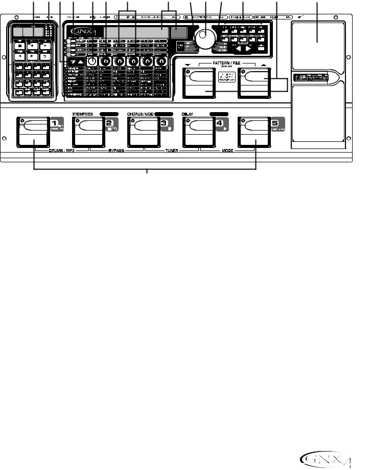
The Front Panel
2 |
3 |
4 |
5 |
6 |
7 |
8 |
9 |
10 |
11 |
12 |
13 |
14 |
15 |
|
|
|
|
|
|
a |
b |
|
|
|
|
|
|
AMP CHANNEL |
CONTROL A |
CONTROL B |
CONTROL C |
TAP TEMPO |
1
1. Footswitches 1-5
Depending on the selected mode, these 5 footswitches select presets, change amp channels, turn individual effects on and off, control drum machine operations, control playback of MP3 files, and give you hands-free operation of the GNX4’s onboard recorder. Drums/MP3, Bypass,Tuner, Mode, and Pattern/File functions are accessed by pressing the labeled pair of footswitches.
2. Recorder Control and USB/Signal Routing Panel
This control panel operates the GNX4’s onboard digital recorder, USB audio routing, and mass storage functions. (See page 68 for more details regarding the Recorder Control and USB/Signal Routing Panel.)
3. Record/Play Level Meters
These 4 Segment LED Meters allow you to monitor the Record/Play signal levels during use.
4. Effect Select Buttons
The Effect Select buttons are used together with the Matrix LEDs to choose the effects you want to edit.
5.Amp Control Buttons
The Amp Control buttons are used to select one of the amp/cabinet model edit rows including: CHAN ONE EQ (Green), GENETX (Yellow), CHAN TWO EQ (Red), and TONE (Silver)
6. Status Button
The Status button is used to select amp channels for editing purposes and to turn each respective amp channel’s EQ on and off. With the CHAN ONE EQ (Green) amp/cabinet model edit row selected, the Status button turns Channel One’s EQ on and off. With the GENETX (Yellow) amp/cabinet model edit row selected, the Status button selects between the Channel One, Channel Two, and the Warp Channels (if a Warped state between both channels exists). With the CHAN TWO EQ (Red) amp/cabinet model
3

Introduction
edit row selected, the Status button turns Channel Two’s EQ on and off. With the TONE (Silver) edit row selected, the Status button selects between Channel One Amp,Warped Amp, and Channel Two Amp. The Amp Gain, Bass, Midrange,Treble, and Amp Levels alternate between editing Channel One’s (lit green) or Channel Two’s (lit red) amp settings as the status button is pressed. When editing effects in the Effect Matrix, the Status Button turns the selected effect on and off, or selects a controller type for the expression assignment.
7. Knobs
Depending on which amp control row or effect row is selected using the Amp Control or Effect Select buttons, these 5 knobs adjust the parameters listed in the column directly above or below each knob.
8.Matrix
a. GeNetX™ Amp Controls Matrix
The GeNetX Amp Controls Matrix displays the GNX4’s Channel One and Channel Two amp types, cabinet types, EQ/tone controls, and cabinet tuning parameters available for editing in each preset.
b. Effects Matrix
The Effects Matrix displays the effects parameters available for editing in each preset.
9. Displays
The Displays give feedback of the various functions that are being used in the GNX4, including preset name, editing functions, tuner, utility menus, drum machine and recorder settings.
10. Preset Bank LEDs
The Preset Bank LEDs indicate whether the selected preset is an internal Factory or User preset, or if the preset is a user preset saved externally on the optional Compact Flash memory card.
11. Data Wheel
The Data Wheel is a multi-function control used for selecting presets, editing preset parameters or for adjusting the settings of the Recorder, Drum Machine, Utility, and Output Setup menus.
12. Status Indicator LEDs (+48V,V-Switch, and USB Active)
The Status Indicator LEDs illuminate when the Microphone Input has +48V Phantom Power active, the Expression Pedal’s V-Switch is engaged, or the USB connection is active.
13. Control Panel Buttons
The Control Panel Buttons are used to select the GNX4’s Footswitch Modes, Output Setups, Utility functions, and to store Amp/Cabinet Model edits and Preset changes. They also access the GNX4’s onboard General MIDI Drum Machine and MP3 Player. The buttons are labeled as follows:
MODE - This button changes the functionality of footswitches 1-5 (see the Footswitch Functions for Modes section on page 59). When the Mode button is lit yellow, footswitches 1-5 toggle effects on and off, change amp channels, or can be assigned to various parameters using the control footswitches. When the Mode button is lit green, footswitches 1-5 select presets in the current preset bank. When the Mode button is lit red, footswitches 1-5 control the GNX4’s recorder functions.
4
Introduction
OUTPUT SETUP - This button selects one of the GNX4 Output Setups: Stereo All, Mono All, Mono 1/4”, Mono XLR, Split 1 and Split 2. Stereo and Mono All have all the input sources (guitar, mic, line, drums, onboard recorder playback and audio playback from USB) routed to both output pairs in either stereo or mono respectively. Split 1 routes the guitar signal to just the 1/4” outputs while all other sources are routed out the XLR outputs. Split 2 is the same as Split 1 but the guitar signal is also routed out the XLR outputs.
UTILITY - This button accesses the GNX4’s global functions including:Volume Pedal Update, V-Switch Threshold/Sensitivity, Expression Pedal Calibration, Preset Bounceback, HandsFree, Bank Naming, MIDI Channel selection, Sysex Bulk Dump, MIDI Preset Dump, User HyperModel™ Amp Dump, MIDI Mapping, MIDI Merge, Drum MIDI, Default Drum Kit, and Factory Reset (see the Utilities section on page 104).
AMP SAVE - This button stores Amp and Cabinet changes (tone, gain, level, amp type, cabinet type, warp, or cabinet tuning) as HyperModels.
STORE - This button is used to save Preset edits to the GNX4’s User Presets or to an optional Compact Flash card.
(STOP/PLAY) - This button is used to turn the GNX4’s General MIDI Drum Machine/MP3 Player on and off.
PATTERN/FILE - Pressing this button and using the DATA WHEEL selects the GNX4’s internal drum patterns, external MIDI, or MP3 files to be played. MIDI and MP3 files must be resident in the GNX4>MIDI and GNX>MP3 directories on your Compact Flash card in order for them to be recognized (see the Memory Card/Computer File Format section on page 103).
LEVEL - This button adjusts the GNX4’s Drum Machine output level or the playback level of MP3s.
TEMPO - This button adjusts the tempo of the GNX4’s Drum Machine. Tempo is ignored when an MP3 is selected.
KIT - This button selects one of the GNX4’s drum kits. Kit is ignored when an MP3 is selected.
EXIT - Exits all functions back to the preset display.
14. Down/Up Footswitches
These footswitches select songs (Recorder Mode), move up and down through the User preset banks (Preset Mode), and navigate through presets (Stompbox/Control Mode). Pressing and holding these footswitches simultaneously temporarily enables them to select the GNX4’s drum patterns or any MIDI and MP3 files available on an optional Compact Flash memory card.
15. Expression Pedal
The Expression Pedal controls effect parameters in real time. Most GNX4 parameters can be assigned to the Expression Pedal. Applying extra pressure to the toe of the Expression Pedal enables the V-Switch feature which changes the Expression Pedal’s function to control the Wah (see V-Switch Threshold/Sensitivity on page 104).
5
Introduction
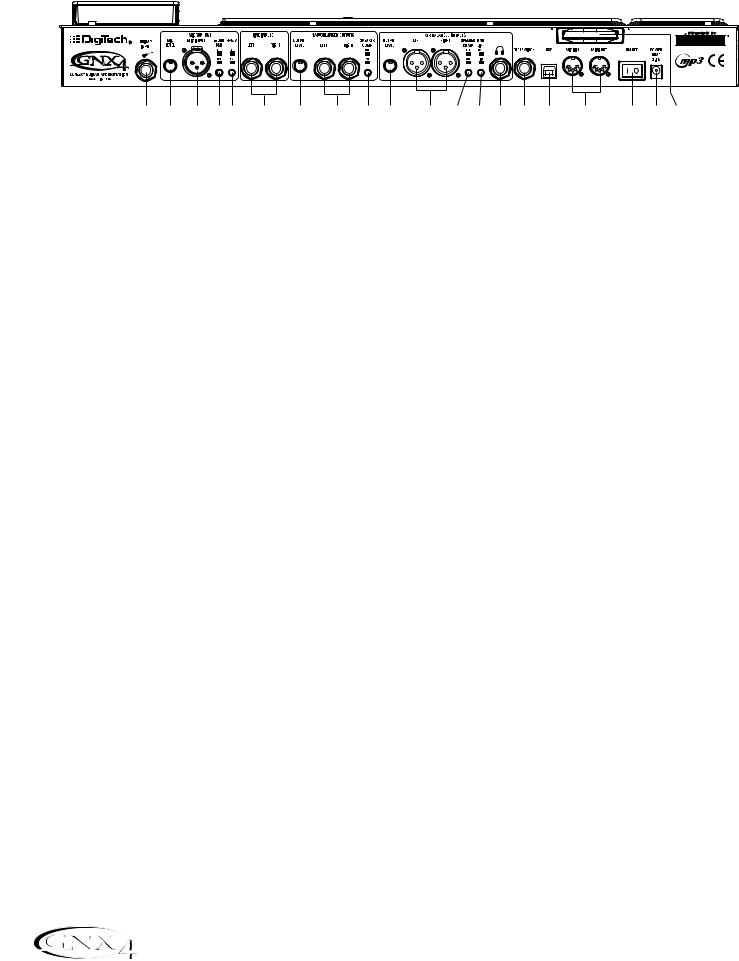
The Rear Panel
|
|
|
|
|
|
|
|
|
|
|
|
|
|
|
|
|
|
|
|
|
|
|
|
|
|
|
|
|
|
|
|
|
|
|
|
|
|
|
|
|
|
|
|
|
|
|
|
|
|
|
|
|
|
|
|
|
|
|
|
|
|
|
|
|
|
|
|
|
|
|
|
|
|
|
|
|
|
|
|
|
|
|
|
|
|
|
|
|
|
|
|
|
|
|
|
|
|
|
|
|
|
|
|
|
|
|
|
|
|
|
|
|
|
|
|
|
|
|
|
|
|
|
|
|
|
|
|
|
|
|
|
|
|
|
|
|
|
|
|
1 |
2 |
3 |
4 5 |
6 |
|
|
7 |
8 |
9 |
10 |
11 |
12 |
|
13 |
14 |
15 |
16 |
17 |
18 |
19 20 |
||||||||||||||
1. Guitar/Instrument Input
Connect your guitar/instrument to this jack.
2. Mic Level
Controls the gain of the mic input preamp.
3. Microphone Input
Connect a low impedance microphone to this jack for recording vocals or acoustic instruments into the GNX4’s Recorder. It can also be used for the Talker™ Vocoder effect (see Talker on page 37). The mic signal can remain dry or processed through the GNX4’s effects for live and recording applications.
4. -20dB Pad Switch
The -20dB pad is a resistive attenuator that drops the level coming from the mic input jack. Its purpose is to give you a way of preventing overload of the preamp when incoming signals become excessive. When the pad is on, the net gain of the preamp is 20dB lower than normal.
5. +48V Phantom Power Switch
This switches on the phantom power to the Microphone Input. Dynamic microphones do not require phantom power to operate, but are not harmed by it. Most condenser microphones do require phantom power to operate. If you are unsure about the phantom power requirements for your microphone, consult your microphone’s documentation or contact the manufacturer.
6. Left/Right Balanced Line Inputs
Connect line level sources to these jacks for recording or live performance mixing into the GNX4. Line signals can remain dry or be processed through the GNX4’s effects for live and recording applications.
7. Output Level (1/4” Outputs Only)
Controls the overall volume level of the 1/4” outputs of the GNX4.
8. Left/Right Line 1/4” Balanced Outputs
Connect these outputs to your guitar amplifier(s), power amplifier(s), or to a mixing console that accepts 1/4” balanced connections.
9. Speaker Compensation Switch (1/4” Outputs Only)
This switch enables Speaker Compensation on the 1/4” Outputs for when they are connected to a full-range speaker system. This switch should be set to the off position when the 1/4” outputs are connected to a guitar amp or power amp/guitar cabinet system.
10. Output Level (XLR and Headphone Outputs Only)
Controls the overall volume level of the balanced XLR and Headphone outputs of the GNX4.
6

Introduction
11. Left/Right XLR Balanced Outputs
Connect these outputs to your power amplifier/speaker system or to a mixing console that accepts XLR balanced connections.
12. Speaker Compensation Switch (XLR and Headphone Outputs Only)
This switch enables Speaker Compensation on the XLR and Headphone Outputs for when they are connected to a full-range speaker system. This switch should be set to the off position when the XLR outputs are connected to a power amp/guitar cabinet system.
13. Ground Lift Switch
This switch lifts pin 1 of the XLR Outputs from all ground references. This may be necessary to break troublesome ground loops that can cause hum in the system, especially when both XLR and 1/4” outputs are used together.
14. Headphone Output
Connect a pair of stereo headphones to this jack. Do not connect a mono plug to this jack, as it may damage the output driver.
15. Footswitch
(Optional ) Connect a GNXFC footswitch to this jack for remote control of the GNX4’s recorder functions.
16. USB Jack
Connect this jack to your computer’s USB port for hard disk recording and computer preset editing via the X-Edit™ Editor/Librarian software. A standard USB cable is included. The GNX4 is compatible with USB 2.0 high speed ports, however the USB 2.0 bus will switch to a USB v1.1 full speed data rate to work with the GNX4.
ATTENTION: Before using the GNX4’s USB connection, it is necessary to first install the USB drivers provided on the X-Edit Software CD. Please read the Software Installation Guide that came with your GNX4 for the proper instructions on how to install the drivers for your operating system.
17. MIDI In
The MIDI In jack receives all incoming MIDI data. MIDI preset changes and CC control messages received from external MIDI devices connected to the MIDI In jack can be used to control the GNX4 and its presets parameters. When the GNX4 is connected to the computer via USB, the MIDI In can be used as a MIDI interface for recording any MIDI data in Pro Tracks Plus™ or other MIDI recording software.
18. MIDI Out/Thru
The MIDI Out/Thru jack sends MIDI data from the GNX4 including system exclusive information and MIDI preset changes. When the GNX4 is connected to the computer via USB, it can act as a MIDI interface for sending MIDI data from Pro Tracks Plus™ or other MIDI recording software to external keyboards or sound modules. When MIDI Merge is enabled in the Utility menu, the MIDI Out acts as a MIDI Thru for any data coming into the GNX4 from the MIDI In jack.
19. Power Switch
Turns the power on and off.
7

Introduction
20. Power Input
Connect only the provided DigiTech PSS3 power supply to this jack.
21. Compact Flash Memory Card Slot
(Optional ) Insert an optional Compact Flash (CF) card in this slot for use with the GNX4’s on board recorder. Songs, Presets, MIDI files, and MP3 files can be saved and retrieved from the CF card as well. The GNX4 can also function as a Compact Flash card reader by using a Compact Flash card (inserted into this slot) and connecting the GNX4 to your computer via the USB port. The Compact Flash card will be recognized as a hard disk (mass storage drive) for transferring files. See Compact Flash Storage/File Transfer on page 102 for more information regarding this function.
NOTE: The GNX4 is compatible with Type I Compact Flash cards only. It is not compatible with Type II cards or IBM/Hitachi Microdrives™.
8
Audio Routing Setups
Setups Introduction
The GNX4 is equipped with four inputs and four outputs that can be configured several different ways for both live and recording applications. These settings determine which pair of outputs the mic, line, and guitar processing are routed to and how the mic or line inputs are routed through the GNX4’s effects
processing.
Output Setups and Speaker Compensation
The GNX4 features both 1/4” and XLR outputs on the rear panel. These jacks let you simultaneously connect the GNX4 to an amplifier/speaker system on stage via the 1/4” outputs and connect directly to your PA system via the XLR outputs. The GNX4 incorporates Speaker Compensation filtering that can be turned on or off independently for each output pair depending on your application needs.
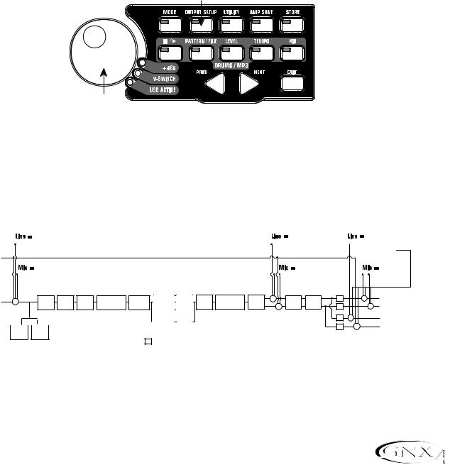
Use the OUTPUT SETUP button along with the DATA WHEEL to select one of the Output Setup options.
Output Setup button
Data Wheel
Control Panel
The six Output Setups are as follows:
steroall - All input sources (guitar, mic, line, drums, onboard 8-track recorder playback and USB playback) are routed to both output pairs in stereo. Speaker Compensation can be turned on and off independently for either the 1/4" or XLR outputs using the Speaker Compensation switch associated with each pair on the rear panel.
|
|
line fx |
line rvb |
line dry |
|||
Line Left |
|
|
|
|
|
|
|
|
|
|
|
|
|
|
DRUMS, |
|
|
|
|
|
|
|
RECORDER, |
Line Right |
|
|
|
|
USB PLAYBACK |
||
|
|
|
|
|
|||
Mic Input |
mic fx |
mic rvb |
|
|
mic dry |
||
|
|
|
|
|
|
||
|
|
|
|
|
|
||
Guitar Input |
+ |
Pickup |
Wah |
Comp |
Whammy/IPS |
Stompbox |
CH 1 Amp |
CH 1 |
Gate |
Whammy/IPS |
Chorus/ |
+ |
SC |
+ |
XLR Left Output |
Sim |
(except |
Modeling/ |
Cabinet |
(Talker) |
Mod |
Delay |
Reverb |
+ |
XLR Right Output |
||||||
|
|
|
|
|
Talker) |
|
Tone |
|
|
|
|
+ |
SC |
|
|
|
|
|
CH 2 Amp |
CH 2 |
|
SC |
+ |
1/4" Left Output |
|
|
|
|
|
Modeling/ |
|
|
|||
|
|
|
|
|
|
|||||
|
|
|
|
|
Cabinet |
|
|
+ |
1/4" Right Output |
|
|
|
|
|
|
Tone |
|
SC |
|||
|
|
|
|
|
|
|
||||
Comp |
|
Gate |
|
|
|
|
|
|||
|
|
|
|
|
||||||
Detector |
|
Detector |
|
|
|
|
|
|||
SC = Speaker Compensation Module
9
Audio Routing Setups
mono all - All input sources (guitar, mic, line, drums, onboard 8-track recorder playback and USB playback) are routed to both output pairs in mono. Speaker Compensation can be turned on and off independently for either the 1/4" or XLR outputs using the Speaker Compensation switch associated with each pair on the rear panel.
|
line fx |
line rvb |
line dry |
|||
Line Left |
|
|
|
|
|
|
|
|
|
|
|
|
|
|
|
|
|
|
DRUMS, |
|
Line Right |
|
|
|
RECORDER, |
|
|
|
|
|
USB PLAYBACK |
|
||
Mic Input |
mic fx |
mic rvb |
|
mic dry |
||
|
|
|
|
|
|
|
|
|
|
|
|
|
|
Guitar Input |
+ |
Pickup |
Wah |
Comp |
Whammy/IPS |
Stompbox |
CH 1 Amp |
CH 1 |
Gate |
Whammy/IPS |
Chorus/ |
+ |
SC |
+ |
+ |
XLR Left Output |
Sim |
(except |
Modeling/ |
Cabinet |
(Talker) |
Mod |
Delay |
Reverb |
+ |
XLR Right Output |
|||||||
|
|
|
|
|
Talker) |
|
Tone |
|
|
|
|
+ |
SC |
|
|
|
|
|
|
CH 2 Amp |
CH 2 |
|
SC |
+ |
+ |
1/4" Left Output |
|
|
|
|
|
Modeling/ |
|
|
||||
|
|
|
|
|
|
||||||
|
|
|
|
|
Cabinet |
|
|
+ |
1/4" Right Output |
||
|
|
|
|
|
Tone |
|
|
SC |
|
||
Comp |
|
Gate |
|
|
|
|
|
|
|||
|
|
|
|
|
|
|
|
||||
|
|
|
|
|
|
||||||
Detector |
|
Detector |
|
|
|
|
|
|
|||
SC = Speaker Compensation Module
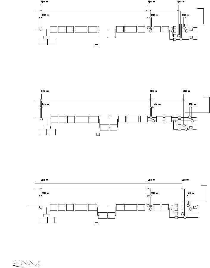
mono 1/4 - All input sources (guitar, mic, line, drums, onboard 8-track recorder playback and USB playback) are routed to the 1/4” outputs in mono. All input sources routed to the XLR outputs maintain stereo separation. Speaker Compensation can be turned on and off independently for either the 1/4" or XLR outputs using the Speaker Compensation switch associated with each pair on the rear panel.
|
|
line fx |
line rvb |
line dry |
||||
Line Left |
|
|
|
|
|
|
|
|
|
|
|
|
|
|
|
DRUMS, |
|
|
|
|
|
|
|
|
RECORDER, |
|
Line Right |
|
|
|
|
USB PLAYBACK |
|
||
|
|
|
|
|
|
|||
Mic Input |
mic fx |
mic rvb |
|
|
mic dry |
|||
|
|
|
|
|
|
|
||
|
|
|
|
|
|
|
||
Guitar Input |
+ |
Pickup |
Wah |
Comp |
Whammy/IPS |
Stompbox |
CH 1 Amp |
CH 1 |
Gate |
Whammy/IPS |
Chorus/ |
+ |
SC |
|
+ |
XLR Left Output |
Sim |
(except |
Modeling/ |
Cabinet |
(Talker) |
Mod |
Delay |
Reverb |
|
+ |
XLR Right Output |
||||||
|
|
|
|
|
Talker) |
|
Tone |
|
|
|
|
+ |
SC |
|
||
|
|
|
|
|
|
|
CH 2 Amp |
CH 2 |
|
|
|
|
SC |
+ |
+ |
1/4" Left Output |
|
|
|
|
|
|
|
Modeling/ |
|
|
|
|
|
||||
|
|
|
|
|
|
|
Cabinet |
|
|
|
|
SC |
+ |
1/4" Right Output |
||
|
Comp |
Gate |
|
|
|
|
Tone |
|
|
|
|
|
|
|||
|
|
|
|
|
|
|
|
|
|
|
|
|
||||
|
|
|
|
|
|
|
|
|
|
|
|
|
|
|
||
|
Detector |
Detector |
|
|
|
|
|
|
|
|
|
|
|
|
|
|
SC = Speaker Compensation Module
mono xlr - All input sources (guitar, mic, line, drums, onboard 8-track recorder playback and USB playback) are routed to the XLR outputs in mono. All input sources routed to the 1/4” outputs maintain stereo separation. Speaker Compensation can be turned on and off independently for either the 1/4" or XLR outputs using the Speaker Compensation switch associated with each pair on the rear panel.
|
line fx |
line rvb |
line dry |
|||
Line Left |
|
|
|
|
|
|
|
|
|
|
|
DRUMS, |
|
Line Right |
|
|
|
RECORDER, |
|
|
|
|
|
USB PLAYBACK |
|
||
|
|
|
|
|
||
Mic Input |
mic fx |
mic rvb |
|
|
mic dry |
|
|
|
|
|
|
|
|
|
|
|
|
|
|
|
Guitar Input |
+ |
Pickup |
Wah |
Comp |
Whammy/IPS |
Stompbox |
CH 1 Amp |
CH 1 |
Gate |
Whammy/IPS |
Chorus/ |
+ |
SC |
+ |
+ |
XLR Left Output |
Sim |
(except |
Modeling/ |
Cabinet |
(Talker) |
Mod |
Delay |
Reverb |
+ |
XLR Right Output |
|||||||
|
|
|
|
|
Talker) |
|
Tone |
|
|
|
|
+ |
SC |
|
CH 2 Amp CH 2 |
SC |
+ |
1/4" Left Output |
|
Modeling/ |
Cabinet |
|
+ |
1/4" Right Output |
Tone |
|
SC |
||
Comp Gate
Detector Detector
SC = Speaker Compensation Module
10
Audio Routing Setups
The SPLIT1 Output mode routes guitar signal to the 1/4” outputs while the mic, line input sources, drums, and audio playback from the onboard 8-track recorder and the computer are routed out the XLR outputs. SPLIT2 is the same as SPLIT1 but the guitar signal with Speaker Compensation is also routed out the XLR outputs.
SPLIT1 - Stereo guitar processing is routed to the 1/4” outputs. Audio playback from the computer, mic, and line sources are routed to the XLR outputs. Speaker Compensation can be individually turned on and off either the 1/4” or XLR outputs using the Speaker Compensation switch located next to each output pair on the rear panel.
|
|
line fx |
line rvb |
line dry |
|||
Line Left |
|
|
|
|
|
|
|
|
|
|
|
|
|
DRUMS, |
|
|
|
|
|
|
|
RECORDER, |
|
Line Right |
|
|
|
USB PLAYBACK |
|
||
|
|
|
|
|
|||
Mic Input |
|
mic fx |
mic rvb |
|
mic dry |
||
|
|
|
|
|
|
|
|
|
|
|
|
|
|
|
|
Guitar Input |
+ |
Pickup |
Wah |
Comp |
Whammy/IPS |
Stompbox |
CH 1 Amp |
CH 1 |
Gate |
Whammy/IPS |
Chorus/ |
+ |
Reverb |
+ |
XLR Left Output |
Sim |
(except |
Modeling/ |
Cabinet |
(Talker) |
Mod |
Delay |
+ |
XLR Right Output |
|||||||
|
|
|
|
Talker) |
|
Tone |
|
+ |
|
CH 2 Amp CH 2 |
|
|
|
SC |
|
|
1/4" Left Output |
|
|
|
|
|
|
||||
Modeling/ |
Cabinet |
|
|
|
|
|
|
1/4" Right Output |
|
|
|
SC |
|
|
|||
Tone |
|
|
|
|
|
|||
|
|
|
|
|
|
|||
Comp Gate
Detector Detector
SC = Speaker Compensation Module
SPLIT2 - Stereo guitar processing is routed to the 1/4” outputs without Speaker Compensation. Stereo guitar processing, audio playback from the computer, mic, and line sources are routed to the XLR outputs with Speaker Compensation. Speaker Compensation can be individually turned on and off either the 1/4” or XLR outputs using the Speaker Compensation switch located next to each output pair on the rear panel.
|
line fx |
line rvb |
line dry |
||
Line Left |
|
|
|
|
|
|
|
|
|
|
DRUMS, |
|
|
|
|
|
RECORDER, |
Line Right |
|
|
|
USB PLAYBACK |
|
|
|
|
|
||
Mic Input |
mic fx |
mic rvb |
|
mic dry |
|
|
|
|
|
|
|
|
|
|
|
|
|
Guitar Input |
+ |
Pickup |
|
|
Whammy/IPS |
|
CH 1 Amp |
CH 1 |
|
Whammy/IPS |
Chorus/ |
+ |
|
SC |
+ |
XLR Left Output |
Wah |
Comp |
(except |
Stompbox |
Modeling/ |
Gate |
+ |
Delay |
Reverb |
+ |
XLR Right Output |
||||||
|
|
Sim |
|
|
Talker) |
|
Tone |
Cabinet |
|
(Talker) |
Mod |
|
SC |
|||
|
|
|
|
|
|
|
|
|
|
|
|
|
CH 2 Amp CH 2 |
|
|
SC |
|
1/4" Left Output |
|
|
|
|
||||
Modeling/ |
Cabinet |
|
|
|
|
1/4" Right Output |
|
|
SC |
|
|||
Tone |
|
|
|
|
||
|
|
|
|
|
|
|
|
|
|
|
|
|
|
Comp Gate
Detector Detector
SC = Speaker Compensation Module
11
Audio Routing Setups
Mic and Line Setups
The Mic and Line Setups are configurations for the mic and line inputs designed for both live performance and recording applications. The GNX4 acts as a mixing device for mic and line sources, and can eliminate the need for a mixer when the GNX4’s outputs are to be plugged directly into a full-range powered speaker system. When enabled, these inputs can be routed around or through the GNX4’s effects processing and then mixed directly into the GNX4’s 1/4” and XLR outputs.
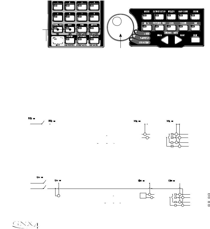
Use the SHIFT>MIC and SHIFT>LINE buttons along with the DATA WHEEL to select the Mic/Line Setup options.
Mic, Line
buttons
Shift button 

|
|
|
Recorder Panel |
Data Wheel |
|
Both Mic and Line inputs have four settings that can be independently selected. They are as follows:
MIC OFF / LINe OFF - Mic and Line inputs are disabled.
MIC DRY / LINe DRY - Inputs routed directly to GNX4’s outputs, bypassing all effects processing. MIC RVB / LINe RVB - Inputs routed through delay and reverb effects of the current preset. MIC FX / LINE FX - Inputs routed through all effects of current preset.
Mic Routing
mic off |
|
|
|
|
|
|
|
|
|
|
|
|
|
|
|
|
|
|
|
|
|
|
|
|
|
|
|
|
|
|
|||
Mic Input |
|
|
mic fx |
|
|
|
|
|
|
|
|
|
|
|
|
|
mic rvb |
|
|
|
|
|
|
|
mic dry |
|
|||||||
|
|
|
|
|
|
|
|
|
|
|
|
|
|
|
|
|
|
|
|
|
|
|
|
|
|
|
|
|
|
|
|
XLR Left Output |
|
|
|
|
|
|
|
|
|
|
|
|
|
|
|
|
|
|
|
|
|
|
+ |
|
|
|
|
|
|
|
|
+ |
|||
|
|
|
Pickup |
|
Wah |
|
Comp |
|
Whammy/IPS |
|
Stompbox |
|
CH 1 Amp |
CH 1 |
|
Gate |
|
Whammy/IPS |
|
Chorus/ |
|
Delay |
|
Reverb |
|
|
SC |
|
|||||
|
|
|
|
|
|
(except |
|
|
Modeling/ |
|
|
|
|
|
|
|
|
|
XLR Right Output |
||||||||||||||
|
|
|
Sim |
|
|
|
|
|
Talker) |
|
|
|
Tone |
Cabinet |
|
|
|
(Talker) |
|
Mod |
|
|
|
|
|
|
|
|
|
|
|
|
|
|
|
|
|
|
|
|
|
|
|
|
|
|
|
|
|
|
|
|
+ |
|
|
|
|
|
SC |
|
+ |
||||||
|
|
|
|
|
|
|
|
|
|
|
|
|
|
|
|
|
|
|
|
|
|
|
|
|
|
|
|
|
|
|
|
|
|
|
|
|
|
|
|
|
|
|
|
|
|
|
CH 2 Amp |
CH 2 |
|
|
|
|
|
|
|
|
|
|
|
|
|
SC |
+ |
1/4" Left Output |
|||
|
|
|
|
|
|
|
|
|
|
|
|
|
Modeling/ |
|
|
|
|
|
|
|
|
|
|
|
|
|
|||||||
|
|
|
|
|
|
|
|
|
|
|
|
|
Tone |
Cabinet |
|
|
|
|
|
|
|
|
|
|
|
|
|
|
|
|
+ |
1/4" Right Output |
|
|
|
|
|
|
|
|
|
|
|
|
|
|
|
|
|
|
|
|
|
|
|
|
|
|
|
|
SC |
|
|
||||
Line Input Routing
line off |
|
|
|
|
|
|
|
|
|
|
|
|
|
|
|
|
|
|
|
|
|
|
|
|
|
|
|
|
|
|
|
|
|
|
|
line fx |
|
|
|
|
|
|
|
|
|
|
|
|
|
|
|
line rvb |
|
|
|
|
line dry |
|
|||||||||
Line Left |
|
|
|
|
|
|
|
|
|
|
|
|
|
|
|
|
|
|
|
|
|
|
|
|
|
|
|
|
|
|
|
|
|
|
|
|
|
|
|
|
|
|
|
|
|
|
|
|
|
|
|
|
|
|
|
|
|
|
|
|
|
|
|
|
|
|
|
Line Right |
|
|
|
|
|
|
|
|
|
|
|
|
|
|
|
|
|
|
|
|
+ |
|
|
|
|
|
|
|
+ |
|
XLR Left OutputSC |
||
|
|
|
|
|
|
|
|
|
|
|
|
|
|
|
|
|
|
|
|
|
|
|
|
|
|
|
|
||||||
|
|
|
|
|
|
|
|
|
|
|
|
|
|
|
|
|
|
|
|
|
|
|
|
|
|
|
|
|
|
||||
+ |
|
Pickup |
|
Wah |
|
Comp |
|
Whammy/IPS |
|
Stompbox |
|
CH 1 Amp |
CH 1 |
|
Gate |
|
Whammy/IPS |
|
Chorus/ |
|
|
Delay |
|
Reverb |
|
|
SC |
|
|||||
|
Sim |
|
|
|
(except |
|
|
Modeling/ |
Cabinet |
|
|
(Talker) |
|
Mod |
|
|
|
|
|
|
|
|
|
XLR Right Output |
|||||||||
|
|
|
|
|
|
|
|
|
|||||||||||||||||||||||||
|
|
|
|
|
|
|
|
|
Talker) |
|
|
|
Tone |
|
|
|
|
|
|
|
|
+ |
|
|
|
|
|
|
|
|
+ |
||
|
|
|
|
|
|
|
|
|
|
|
|
|
|
|
|
|
|
|
|
|
|
|
|
|
|
|
SC |
|
|
|
SC |
||
|
|
|
|
|
|
|
|
|
|
|
|
|
|
|
|
|
|
|
|
|
|
|
|
|
|
|
|
|
|
|
|
|
|
|
|
|
|
|
|
|
|
|
|
|
|
|
CH 2 Amp |
CH 2 |
|
|
|
|
|
|
|
|
|
|
|
|
|
|
|
+ |
|
1/4" Left Output |
|
|
|
|
|
|
|
|
|
|
|
|
|
|
|
|
|
|
|
|
|
|
|
|
|
|
|
||||||||
|
|
|
|
|
|
|
|
|
|
|
|
|
Modeling/ |
|
|
|
|
|
|
|
|
|
|
|
|
|
|
|
|
||||
|
|
|
|
|
|
|
|
|
|
|
|
|
|
|
|
|
|
|
|
|
|
|
|
|
|
|
|
SC |
|
|
|
SC |
|
|
|
|
|
|
|
|
|
|
|
|
|
|
Tone |
Cabinet |
|
|
|
|
|
|
|
|
|
|
|
|
|
|
SC |
|
|
+ |
1/4" Right Output |
|
|
|
|
|
|
|
|
|
|
|
|
|
|
|
|
|
|
|
|
|
|
|
|
|
|
|
|
|
|
||||
12

Audio Routing Setups
Optimizing the Mic Input Level
To adjust the microphone input level for optimal use, you must first setup the GNX4’s Record Level meter located on the Recorder Control and USB/Signal Routing Panel to monitor the live microphone signal. To do this, follow these steps:
1.Press the SHIFT button located on the Recorder Control and USB/Signal Routing Panel and then press the CF/USB 1-2 SRC button.
2.Then use the DATA WHEEL to select your desired input routing source (STEREOfx, STEROALL,
MONO fx, MONO ALL, SUM+DGTR, SUM+MIC, DGTR+MIC, or DRY MIC). STEREOfx and mono fx will only work if the Mic Input is selected properly. (See page 64 for more information regarding the
GNX4 Input Sources.) Also, if the mic is routed through MIC RVB or MIC FX, the active effect’s level can impact the levels shown in the meters.
3.Talk or sing into the mic as intended for use and adjust the GNX4’s Microphone Input Level knob located on the rear panel until the level consistently lights just below the 0 dB clip point on the REC LEVEL meter. Utilize the -20 dB pad switch also located on the GNX4’s rear panel if the level is too high to provide proper headroom.
NOTE: If your microphone requires phantom power, first make sure the microphone is connected, then press the Phantom Power switch (labeled +48V) located on the rear panel of the GNX4. The +48V LED located next to the DATA WHEEL indicates the phantom power is active. If your mics don’t need phantom power, it is best to turn it off.
Optimizing the Line Input Levels
To adjust the line input levels for optimal use, you must first setup the GNX4’s Record Level meter located on the Recorder Control and USB/Signal Routing Panel to monitor the live line input signals. To do this, follow these steps:
1.Press the SHIFT button located on the Recorder Control and USB/Signal Routing Panel and then press the CF/USB 1-2 SRC button.
2.Then use the DATA WHEEL to select your desired input routing source (STEREOfx, STEROALL,
MONO fx, MONO ALL, SUM+DGTR, or DRY line). STEREOfx and mono fx will only work if the Line Inputs are selected properly. (See page 64 for more information regarding the GNX4 Input
Sources.) Also, if the lines are routed through line RVB or line FX, the active effect’s level can impact the levels shown in the meters.
3.Play audio back from your external audio device (mixer, keyboard, CD player, etc.) and adjust its output level until the level consistently lights just below the 0 dB clip point on the GNX4’s REC LEVEL meter.
13
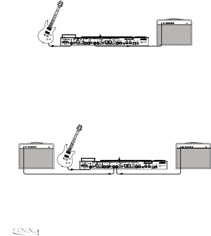
Making Connections
For Live Performance
The GNX4 was designed to be extremely flexible to meet any of your application needs. For many GNX4 users, its primary purpose will be for use in live performances. Whether you are a solo performer who spends weekends playing at a small club or the power-user playing the largest venues each night, the GNX4 has just what you need to do the gig right. The following diagrams show examples of how to utilize the GNX4 in typical live performance applications.
Before connecting the GNX4, make sure both the GNX4 and your amplifier(s) are turned OFF.
Small Club Setup (Mono Amp Rig)
Amplifier
Guitar
Speaker Compensation Switch (1/4" Outputs)
Guitar Input |
Left 1/4" Balanced Output |
This diagram demonstrates a minimum setup for using the GNX4 in a typical, small club performance setup. All you need is your guitar, a couple of guitar cables, and an amp. This connection scheme also applies for use with a power amp/speaker cabinet rig.
1.Connect your guitar to the GNX4’s Guitar Input.
2.Connect a single mono instrument cable from the Left 1/4” Balanced Output of the GNX4 to the instrument input or the effect return on your amplifier.
3.Switch the GNX4’s Speaker Compensation for the 1/4” Balanced Outputs to the OFF position.
4.Press the GNX4’s Output Setup button and select “MONO 1/4” mode using the Data Wheel.
NOTE: When using a guitar amp(s), it may be best to connect the GNX4’s Output to your
amp’s effects return to avoid coloration of the tone due to the amplifier’s tone controls.
Medium Stage Setup (Stereo Amp Rig)
Amplifier |
Amplifier |
Guitar
Speaker Compensation Switch (1/4" Outputs)
Guitar Input
1/4" Balanced Outputs
Whether your gig is at a large club or a small hall, nothing beats running your guitar in stereo. This diagram demonstrates a typical setup using your GNX4’s line outputs, and two guitar combo amps.
1.Connect your guitar to the GNX4’s Guitar Input.
2.Connect mono instrument cables from the Left and Right 1/4” Balanced Outputs of the GNX4 to the instrument inputs or the effect returns on your amplifiers.
3.Switch the GNX4’s Speaker Compensation for the 1/4” Balanced Outputs to the OFF position.
4.Press the GNX4’s Output Setup button and select “STEROAll” mode using the Data Wheel.
14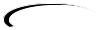
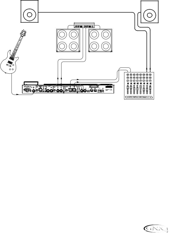
Making Connections
Large Stage Setup (Stereo Amp/Cabinet Rig)
PA Speaker (Left) |
PA Speaker (Right) |
||||
|
|
|
|
|
|
|
|
|
|
|
|
Stereo Power Amp
2- Speaker Cabs
Guitar
1/4" Balanced |
XLR Balanced Outputs |
Outputs |
|
Guitar Input |
|
|
|
|
|
|
|
|
|
|
|
Speaker Compensation |
Speaker Compensation |
||||
Switch (1/4" Outputs) |
|
Switch (XLR Outputs) |
|||
|
|
|
|
|
|
|
Mixer |
|
|
|
|
|
|
|
|
|
|||||||||
4 |
6 |
|
4 |
6 |
|
4 |
6 |
|
4 |
6 |
|
4 |
|
6 |
|
4 |
|
6 |
4 |
|
6 |
|
4 |
|
6 |
2 |
|
8 |
2 |
|
8 |
2 |
|
8 |
2 |
|
8 |
2 |
|
|
8 |
2 |
|
8 |
2 |
|
|
8 |
2 |
|
8 |
0 |
Aux 1 |
10 |
0 |
Aux 1 |
10 |
0 |
Aux 1 |
10 |
0 |
Aux 1 |
10 |
0 |
Aux 1 |
10 |
|
0 |
Aux 1 |
10 |
0 |
Aux 1 |
10 |
|
0 |
Aux 1 |
10 |
4 |
6 |
|
4 |
6 |
|
4 |
6 |
|
4 |
6 |
|
4 |
|
6 |
|
4 |
|
6 |
4 |
|
6 |
|
4 |
|
6 |
2 |
|
8 |
2 |
|
8 |
2 |
|
8 |
2 |
|
8 |
2 |
|
|
8 |
2 |
|
8 |
2 |
|
|
8 |
2 |
|
8 |
0 |
Aux 2 |
10 |
0 |
Aux 2 |
10 |
0 |
Aux 2 |
10 |
0 |
Aux 2 |
10 |
0 |
Aux 2 |
10 |
|
0 |
Aux 2 |
10 |
0 |
Aux 2 |
10 |
|
0 |
Aux 2 |
10 |
-1 0 +1 |
|
-1 0 +1 |
|
-1 0 +1 |
|
-1 0 +1 |
|
-1 0 +1 |
|
-1 0 +1 |
-1 0 +1 |
|
-1 0 +1 |
||||||||||||
-2 |
|
+2 |
-2 |
|
+2 |
-2 |
|
+2 |
-2 |
|
+2 |
-2 |
|
+2 |
-2 |
|
+2 |
-2 |
|
+2 |
-2 |
|
+2 |
||
-3 |
|
+3 -3 |
|
+3 -3 |
|
+3 -3 |
|
+3 -3 |
|
|
+3 -3 |
|
+3 -3 |
|
|
+3 -3 |
|
+3 |
|||||||
-4 |
|
+4 |
-4 |
|
+4 |
-4 |
|
+4 |
-4 |
|
+4 |
-4 |
|
|
+4 |
-4 |
|
+4 |
-4 |
|
|
+4 |
-4 |
|
+4 |
-5 |
Pan |
+5 |
-5 |
Pan |
+5 |
-5 |
Pan |
+5 |
-5 |
Pan |
+5 |
-5 |
Pan |
+5 |
|
-5 |
Pan |
+5 |
-5 |
Pan |
+5 |
|
-5 |
Pan |
+5 |
Mute |
|
|
Mute |
|
|
Mute |
|
|
Mute |
|
|
Mute |
|
|
|
Mute |
|
|
Mute |
|
|
|
Mute |
|
|
L / R |
|
|
L / R |
|
|
L / R |
|
|
L / R |
|
|
L / R |
|
|
|
L / R |
|
|
L / R |
|
|
|
L / R |
|
|
+10 |
|
|
+10 |
|
|
+10 |
|
|
+10 |
|
|
+10 |
|
|
|
+10 |
|
|
+10 |
|
|
|
+10 |
|
|
+5 |
|
|
+5 |
|
|
+5 |
|
|
+5 |
|
|
+5 |
|
|
|
+5 |
|
|
+5 |
|
|
|
+5 |
|
|
0 |
|
|
0 |
|
|
0 |
|
|
0 |
|
|
0 |
|
|
|
0 |
|
|
0 |
|
|
|
0 |
|
|
-5 |
|
|
-5 |
|
|
-5 |
|
|
-5 |
|
|
-5 |
|
|
|
-5 |
|
|
-5 |
|
|
|
-5 |
|
|
-10 |
|
|
-10 |
|
|
-10 |
|
|
-10 |
|
|
-10 |
|
|
|
-10 |
|
|
-10 |
|
|
|
-10 |
|
|
-20 |
|
|
-20 |
|
|
-20 |
|
|
-20 |
|
|
-20 |
|
|
|
-20 |
|
|
-20 |
|
|
|
-20 |
|
|
-30 |
|
|
-30 |
|
|
-30 |
|
|
-30 |
|
|
-30 |
|
|
|
-30 |
|
|
-30 |
|
|
|
-30 |
|
|
-∞ |
|
|
-∞ |
|
|
-∞ |
|
|
-∞ |
|
|
-∞ |
|
|
|
-∞ |
|
|
-∞ |
|
|
|
-∞ |
|
|
|
1 |
|
|
2 |
|
|
3 |
|
|
4 |
|
|
5 |
|
|
|
6 |
|
|
|
|
|
|
|
|
A large stage rig lets you really pull out all the stops since space isn’t necessarily an issue, but volume usually is. For this application, plug your guitar into the GNX4 and connect mono instrument cables from the GNX4’s 1/4” outputs into a stereo power amp feeding two cabinets. Using two cabinets gives you much more dramatic stereo separation and helps widen the sweet spot for your sound when you move onstage. Another great idea is to run the GNX4’s XLR outputs directly into the house P.A. and have the sound engineer control your front of house volume in the overall mix. Then if you need to turn up your stage volume, you won’t upset him by trying to rebalance your guitar volume in the house mix. This diagram demonstrates a typical, large stage performance setup.
1.Connect your guitar to the GNX4’s Guitar Input.
2.Connect mono instrument cables from the GNX4’s Left and Right 1/4” Line Outputs to a stereo power amplifier amplifier and switch the 1/4” Outputs Speaker Compensation to the OFF position.
3.Connect XLR cables from the GNX4’s Left and Right XLR outputs to the house P.A. mixer and switch the XLR Outputs Speaker Compensation to the ON position.
4.Press the GNX4’s OUTPUT SETUP button and select “STEROALL“ as the output mode using the
DATA WHEEL.
15
Making Connections
Talker™ Performance Setup
Microphone
Guitar
Amplifier
Microphone |
Left 1/4" Balanced Output |
Input |
Guitar Input |
|
|
|
|
|
|
|
|
|
Speaker Compensation Switch (1/4" Outputs) |
||||
The GNX4’s built-in Talker effect creates a talk box effect. To create this effect you must plug a microphone into the GNX4’s mic input and select one of the five Talker types in the Whammy™/IPS/Talk module of a preset. Then as you play your guitar talk into the microphone to emulate the talk box effect. The Talker can be used with any output setup, but for this diagram it will be shown in conjunction with a mono amp rig.
1.Connect your guitar to the GNX4’s Guitar Input.
2.Connect a single mono instrument cable from the Left 1/4” Line Output of the GNX4 to the instrument input or the effect return on your amplifier and switch the 1/4” Balanced Outputs Speaker Compensation to the OFF position.
3.Connect a microphone to the GNX4’s Mic Input using an XLR cable.
4.Select one of the five Talker types in the Whammy/IPS/Talk module of a preset.
5.Press the GNX4’s OUTPUT SETUP button and select “MONO 1/4“ as the output mode using the
DATA WHEEL.
6.Use the Mic Level control knob located next to the Mic Input on the GNX4’s rear panel to adjust the microphone output level. To adjust your microphone input level for optimal use see Optimizing the Mic Input Level on page 13.
16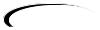
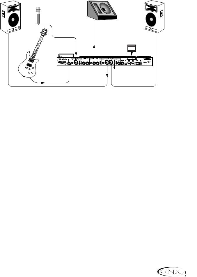
Making Connections
Coffee House/Solo Performance Setup
PA Speaker (Left) |
Powered Monitor |
PA Speaker (Right) |
Microphone
|
Left 1/4" |
CF Card |
|
CompactFlash® |
|
|
|
256 MB |
Mic Input |
Output |
|
Guitar |
|
|
Guitar Input |
XLR Balanced Outputs |
Speaker Compensation |
|
|
 Switch (XLR Outputs)
As a solo performer, we all know how important it is to minimize the amount of gear we have to cart to a gig. For the more elaborate system, this may include electronic keyboards, a CD player, and a mixer. The GNX4 virtually eliminates the need for most of this hardware. First, for your backing tracks, just rip your CD audio tracks into MP3s and place these in the MP3 folder created by the GNX4 on the compact flash card. If you need a mic for vocals or an acoustic instrument, just plug it into the GNX4’s mic input. You have a variety of routings you can select from including taking advantage of the GNX4’s effects processing. For the more advanced setup or if you have a partner on keyboards, just plug them into the GNX4’s line inputs and select the appropriate routing needed. Everything can now be run out the GNX4’s XLR outputs directly into powered speakers. You can even run to a floor monitor out one of the available 1/4” Line Outputs and enable Speaker Compensation on both pairs of outputs.
1.Connect your guitar to the GNX4’s Guitar Input.
2.Connect a microphone to the GNX4’s XLR Mic Input use the Mic Level control knob located next to the Mic Input on the GNX4’s rear panel to adjust the microphone output level. To adjust your microphone input level for optimal use see Optimizing the Mic Input Level on page 13.
3.Connect a mono instrument cable from the GNX4’s Left 1/4” Line Output to a powered monitor.
4.Connect the GNX4’s balanced XLR Left and Right Outputs to a pair of powered PA speakers.
5.Switch the Speaker Compensation on for both the XLR and 1/4” outputs.
6.Press the GNX4’s OUTPUT SETUP button and select “STEROALL” as the output mode using the
DATA WHEEL.
7.Use the Mic Level control knob located next to the Mic Input on the GNX4’s rear panel to adjust the microphone output level. To adjust your microphone input level for optimal use see Optimizing the Mic Input Level on page 13.
17
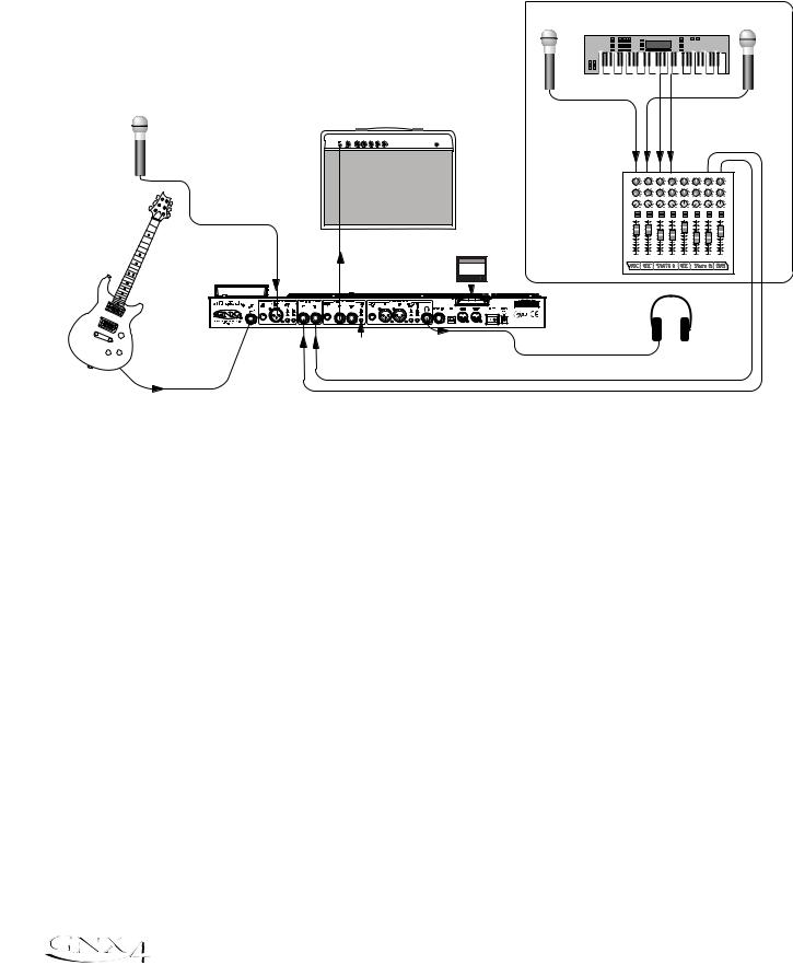
Making Connections
For Recording
The GNX4 also offers great flexibility for recording applications. Listed below are a couple typical recording setups.
Onboard Recorder Application
- Advanced Setup -
|
Amplifier |
|
Microphone |
|
|
|
|
CF Card |
Mic Input |
Left 1/4" |
CompactFlash® |
256 MB |
||
|
Balanced Output |
|
Guitar Input |
Line |
Speaker Compensation |
|
Inputs |
|
|
Switch (1/4" Outputs) |
|
|
|
|
|
|
|
|
Keyboard |
|||
Microphone |
|
|
|
|
|
|
|
Microphone |
Mixer |
+10 |
+10 |
+10 |
+10 |
+10 |
+10 |
+10 |
+10 |
|
+5 |
+5 |
+5 |
+5 |
+5 |
+5 |
+5 |
+5 |
|
0 |
0 |
0 |
0 |
0 |
0 |
0 |
0 |
|
-5 |
-5 |
-5 |
-5 |
-5 |
-5 |
-5 |
-5 |
|
-10 |
-10 |
-10 |
-10 |
-10 |
-10 |
-10 |
-10 |
|
-20 |
-20 |
-20 |
-20 |
-20 |
-20 |
-20 |
-20 |
|
-30 |
-30 |
-30 |
-30 |
-30 |
-30 |
-30 |
-30 |
|
-∞ |
-∞ |
-∞ |
-∞ |
-∞ |
-∞ |
-∞ |
-∞ |
|
1 |
2 |
3 |
4 |
5 |
6 |
7 |
8 |
Headphones |
|
|
|
|
|
|
||
Ever had a moment where the band just clicked with a great song idea? Then you came back the next night to go over it again and….how did that go? Never again thanks to the GNX4’s onboard recorder and its ability to remotely capture that idea forever. Just plug a mic into the GNX4’s mic input, or if you have multiple mics and a mixer, use the stereo output of the mixer into the GNX4’s Line Inputs. Use the Shift>CF/USB 1-2 Source buttons located on the GNX4’s Recorder Panel to set the output routing to “STEROALl“ and hit record. Now you can ensure that spontaneous genius will never be lost again.
1.Connect your guitar to GNX4’s Guitar Input.
2.Connect a microphone to the GNX4’s Mic Input and use the Mic Level control knob located next to the Mic Input on the GNX4’s rear panel to adjust the microphone output level. To adjust your microphone input level for optimal use see Optimizing the Mic Input Level on page 13.
3.Connect a single mono instrument cable from the GNX4’s Left 1/4” Balanced Output to the instrument input or the effect return on your amplifier and switch the 1/4” Balanced Outputs Speaker Compensation to the OFF position.
4.Connect a pair of stereo headphones to the Headphone Output.
5.(Advanced Setup) Connect microphones and a keyboard to your mixer and connect the mixer’s stereo outputs to the GNX4’s Left and Right Line Inputs. To adjust your line input levels for optimal use see
Optimizing the Line Input Levels on page 13.
6.Press the GNX4’s OUTPUT SETUP button and select “STEROALL” as the output mode using the
DATA WHEEL.
7.Optimize your recording levels by either increasing or decreasing your source material’s signal level or by using the GNX4’s SHIFT>CF/USB 1-2 LVL button along with the DATA WHEEL and adjust the levels while playing your guitar. It is best that the recording level consistently lights the -6dB LED on the meter. (See the Using the Record and Playback Meters section on page 76 for more information on optimizing your recording and playback levels.)
18
|
Making Connections |
||
Computer Recording Application |
|
|
|
Computer |
|
|
|
Powered Studio Monitor |
USB Cable |
Powered Studio Monitor |
|
|
|
|
|
Microphone |
|
|
|
|
|
MIDI |
Audio |
MIDI Keyboard
|
|
XLR |
CF Card |
|
|
Balanced |
256 MB |
|
|
|
CompactFlash |
|
Mic Input |
Outputs |
|
|
|
|
|
Guitar |
Guitar |
Line Inputs |
|
Input |
|
|
|
|
|
|
1 |
2 |
3 |
4 |
5 |
6 |
7 |
8 |
L |
R |
Stereo Mixer
Bass Guitar
|
|
|
|
|
|
|
|
Headphones |
GNXFC Foot Controller |
||||||
|
(Optional) |
||||||
|
|
||||||
At the heart of your recording studio, the GNX4 serves both as your guitar processor and audio/MIDI interface. With microphone input, line inputs, and MIDI I/O, you have a full featured interface for recording almost any source you can think of. Connect your guitar or bass to the GNX4’s Guitar/Instrument input and use the amp models for tracking your guitar and bass parts. Next, plug in the mic and get your vocal or acoustic performance nailed. You can even add line level instruments or feeds from submixes in and record these and all of this completely hands-free. Even your MIDI keyboard performance can be recorded so you can try the part with different synth voices later.
Since the GNX4 has professional balanced outputs, you can plug directly into your favorite powered monitors and get the bonus of latency free recording to boot.
1.Connect your guitar (or bass guitar) to the GNX4’s Guitar Input.
2.Connect a microphone to the GNX4’s Mic Input and use the Mic Level control knob located next to the Mic Input on the GNX4’s rear panel to adjust the microphone output level. To adjust your microphone input level for optimal use see Optimizing the Mic Input Level on page 13.
3.Connect a pair of stereo headphones to the Headphone Output.
4.Connect a keyboard, line level instrument, or stereo mixer (for feeding submixes) to the GNX4’s Left and Right Line Inputs. To adjust your line input levels for optimal use see Optimizing the Line Input Levels on page 13.
5.Connect a GNXFC Foot Controller (optional) to the GNX4’s Footswitch jack.
6.Connect a MIDI keyboard to the GNX4’s MIDI In and Out/Thru jacks using 5 Pin MIDI cables.
7.Connect XLR cables from the GNX4’s Left and Right XLR outputs to powered studio monitors.
8.Connect the GNX4 to your computer’s USB jack using the included USB cable.
ATTENTION: Before using the GNX4’s USB connection, it is necessary to first install the USB drivers provided on the X-Edit™ Software CD. Consult the Software Installation Guide that came with your GNX4 for the proper instructions on how to install the drivers for your operating system.
9.Press the GNX4’s OUTPUT SETUP button and select “STEROALL” as the output mode using the
DATA WHEEL.
19
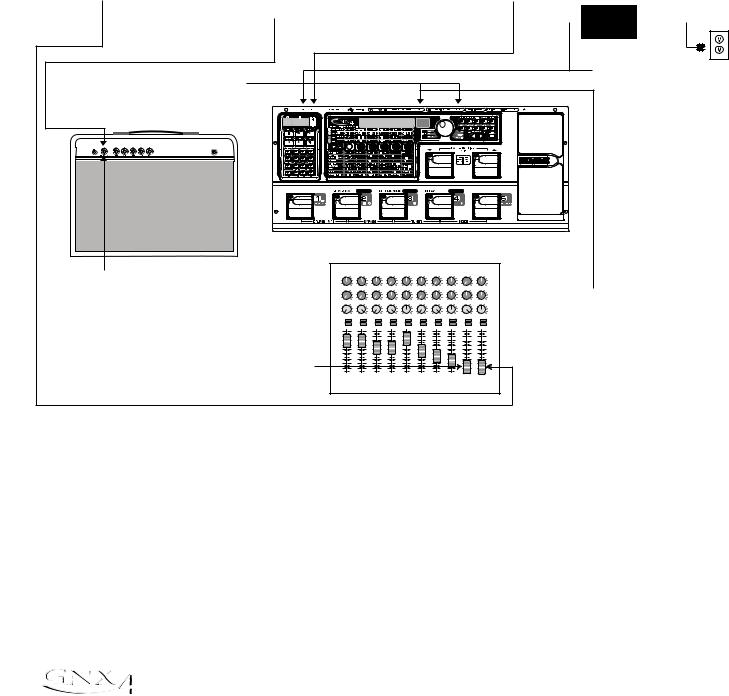
Making Connections
Applying Power
Before applying power to anything, set your amp(s) to a clean tone and set the tone controls to a flat EQ response (on most amps, this would be 0 or 5 on the tone controls). Then do the following:
1.Turn your amp volume all the way down.
2.Pull the mixer’s master faders all the way down.
3.Turn the GNX4’s Output Level knobs all the way down (fully counter-clockwise).
4.Connect the plug of the PSS3 power supply to the GNX4’s Power Jack. Connect the other end of the PSS3 power supply to an AC outlet.
5.Turn the GNX4’s power on.
6.Turn your amplifier(s) on and adjust the volume(s)to a normal playing level.
7.Push the mixer’s master faders up to the desired listening level.
8.Gradually increase the GNX4’s Output Levels to the desired listening level.
7. Push the Master Faders |
6.Turn your Amp on and |
5.Turn the GNX4 on. |
|
|||
up to the desired |
|
adjust the Volume to |
|
|
|
|
|
|
|
|
|
||
|
|
|
|
|||
listening level. |
|
a normal playing |
|
|
PSS3 |
|
|
|
|
|
|
|
|
|
|
|
|
|
Power Supply |
|
|
level. |
|
|
|
|
|
|
|
|
|
|
|
|
|
|
|
|
|
|
|
|
|
|
|
|
|
|
|
|
|
|
|
|
||
|
|
|
|
|
|
|
|
|
|
|
|
|
|
|
|
|
|
|
|
|
|
|
|
|
|
|
|
|
|
|
|
|
|
|
4. Connect the PSS3 to the |
8.Turn the GNX4's Output |
|
|
|
|
|
|
|
|
|
|
|
|
|
|
|
|
|
|
|
|
|
|
|
|
|
|
|
|
|
|
|
|
|
|
GNX4's Power Jack and |
Level knobs up to the |
|
|
|
|
|
|
|
|
|
|
|
|
|
|
|
|
|
|
|
|
|
|
|
|
|
|
|
|
|
|
|
|
|
|
connect the other end of |
desired listening level. |
|
|
|
|
|
|
|
|
|
|
|
|
|
|
|
|
|
|
|
|
|
|
|
|
|
|
|
|
|
|
|
|
|
|
the PSS3 to an AC outlet. |
AMP CHANNEL |
|
|
|
CONTROL A |
|
|
|
|
|
|
CONTROL B |
|
|
|
|
|
|
CONTROL C |
|
TAP TEMPO |
|
||||||||||||||
1.Turn your Amp Volume down. |
4 |
|
6 |
4 |
|
6 |
|
4 |
6 |
|
4 |
|
6 |
|
4 |
|
6 |
|
4 |
6 |
|
4 |
6 |
|
4 |
|
6 |
|
4 |
6 |
|
4 |
|
6 |
|
|
2 |
|
8 |
2 |
|
|
8 |
2 |
|
8 |
2 |
|
|
8 |
2 |
|
|
8 |
2 |
|
8 |
2 |
|
8 |
2 |
|
|
8 |
2 |
|
8 |
2 |
|
8 |
|
|
0 |
Aux 1 |
10 |
0 |
Aux 1 |
|
10 |
0 |
Aux 1 |
10 |
0 |
Aux 1 |
10 |
|
0 |
Aux 1 |
|
10 |
0 |
Aux 1 |
10 |
0 |
Aux 1 |
10 |
0 |
Aux 1 |
|
10 |
0 |
Aux 1 |
10 |
0 |
Aux 1 |
10 |
|
|
4 |
|
6 |
4 |
|
6 |
|
4 |
6 |
|
4 |
|
6 |
|
4 |
|
6 |
|
4 |
6 |
|
4 |
6 |
|
4 |
|
6 |
|
4 |
6 |
|
4 |
|
6 |
3.Turn the GNX4's Ouput |
|
2 |
|
8 |
2 |
|
|
8 |
2 |
|
8 |
2 |
|
|
8 |
2 |
|
|
8 |
2 |
|
8 |
2 |
|
8 |
2 |
|
|
8 |
2 |
|
8 |
2 |
|
8 |
|
|
0 |
Aux 2 |
10 |
0 |
Aux 2 |
|
10 |
0 |
Aux 2 |
10 |
0 |
Aux 2 |
10 |
|
0 |
Aux 2 |
|
10 |
0 |
Aux 2 |
10 |
0 |
Aux 2 |
10 |
0 |
Aux 2 |
|
10 |
0 |
Aux 2 |
10 |
0 |
Aux 2 |
10 |
|
|
-1 0 +1 |
-1 0 +1 |
+4 |
-1 0 +1 |
-1 0 +1 |
+4 |
-1 0 +1 |
+4 |
-1 0 +1 |
-1 0 +1 |
-1 0 +1 |
+4 |
-1 0 +1 |
-1 0 +1 |
Level knobs down. |
||||||||||||||||||||
|
-4 |
|
+4 |
-4 |
|
|
-4 |
|
+4 |
-4 |
|
|
-4 |
|
|
-4 |
|
+4 |
-4 |
|
+4 |
-4 |
|
|
-4 |
|
+4 |
-4 |
|
+4 |
|||||
|
-2 |
|
+2 |
-2 |
|
|
+2 |
-2 |
|
+2 |
-2 |
|
+2 |
-2 |
|
|
+2 |
-2 |
|
+2 |
-2 |
|
+2 |
-2 |
|
|
+2 |
-2 |
|
+2 |
-2 |
|
+2 |
|
|
|
-3 |
|
+3 -3 |
|
|
+3 -3 |
|
+3 -3 |
|
|
+3 -3 |
|
|
+3 -3 |
|
+3 -3 |
|
+3 -3 |
|
|
+3 -3 |
|
+3 -3 |
|
+3 |
|
|||||||||
|
-5 |
Pan |
+5 |
-5 |
Pan |
+5 |
-5 |
Pan |
+5 |
-5 |
Pan |
+5 |
|
-5 |
Pan |
+5 |
-5 |
Pan |
+5 |
-5 |
Pan |
+5 |
-5 |
Pan |
+5 |
-5 |
Pan |
+5 |
-5 |
Pan |
+5 |
|
|||
|
Mute |
|
|
Mute |
|
|
|
Mute |
|
|
Mute |
|
|
|
Mute |
|
|
|
Mute |
|
|
Mute |
|
|
Mute |
|
|
|
Mute |
|
|
Mute |
|
|
|
|
L / R |
|
|
L / R |
|
|
|
L / R |
|
|
L / R |
|
|
|
L / R |
|
|
|
L / R |
|
|
L / R |
|
|
L / R |
|
|
|
L / R |
|
|
L / R |
|
|
|
|
+10 |
|
|
+10 |
|
|
|
+10 |
|
|
+10 |
|
|
|
+10 |
|
|
|
+10 |
|
|
+10 |
|
|
+10 |
|
|
|
+10 |
|
|
+10 |
|
|
|
|
+5 |
|
|
+5 |
|
|
|
+5 |
|
|
+5 |
|
|
|
+5 |
|
|
|
+5 |
|
|
+5 |
|
|
+5 |
|
|
|
+5 |
|
|
+5 |
|
|
|
|
0 |
|
|
0 |
|
|
|
0 |
|
|
0 |
|
|
|
0 |
|
|
|
0 |
|
|
0 |
|
|
0 |
|
|
|
0 |
|
|
0 |
|
|
|
|
-5 |
|
|
-5 |
|
|
|
-5 |
|
|
-5 |
|
|
|
-5 |
|
|
|
-5 |
|
|
-5 |
|
|
-5 |
|
|
|
-5 |
|
|
-5 |
|
|
|
2. Pull Master Faders |
-10 |
|
|
-10 |
|
|
|
-10 |
|
|
-10 |
|
|
|
-10 |
|
|
|
-10 |
|
|
-10 |
|
|
-10 |
|
|
|
-10 |
|
|
-10 |
|
|
|
-30 |
|
|
-30 |
|
|
|
-30 |
|
|
-30 |
|
|
|
-30 |
|
|
|
-30 |
|
|
-30 |
|
|
-30 |
|
|
|
-30 |
|
|
-30 |
|
|
|
|
|
-20 |
|
|
-20 |
|
|
|
-20 |
|
|
-20 |
|
|
|
-20 |
|
|
|
-20 |
|
|
-20 |
|
|
-20 |
|
|
|
-20 |
|
|
-20 |
|
|
|
down completely. |
-∞ |
|
|
-∞ |
|
|
|
-∞ |
|
|
-∞ |
|
|
|
-∞ |
|
|
|
-∞ |
|
|
-∞ |
|
|
-∞ |
|
|
|
-∞ |
|
|
-∞ |
|
|
|
|
1 |
|
|
2 |
|
|
|
3 |
|
|
4 |
|
|
|
5 |
|
|
|
6 |
|
|
7 |
|
|
8 |
|
|
|
L |
|
|
R |
|
|
|
20
 Loading...