


31-735
6" Belt/12" Disc
Abrasive Finishing
Machine
Appareil de finition abrasif à disque de 305 mm (12 po)/à courroie de 152 mm (6 po)
Máquina para acabados abrasivos con banda de
152 mm (6") y disco de
305 mm (12")
A21536 - 02-07-07
Copyright © 2007 Delta Machinery
Instruction Manual Manuel d’utilisation Manual de instrucciones
FRANÇAIS (27) |
ESPAÑOL (52) |
|
|
www.deltamachinery.com
(800) 223-7278 - US
(800) 463-3582 - CANADA

TABLE OF CONTENTS
IMPORTANT SAFETY INSTRUCTIONS .................... |
2 |
TROUBLESHOOTING ................................................ |
23 |
SAFETY GUIDELINES - DEFINITIONS ..................... |
2 |
MAINTENANCE.......................................................... |
23 |
GENERAL SAFETY RULES ....................................... |
3 |
SERVICE..................................................................... |
24 |
ADDITIONAL SPECIFIC SAFETY RULES ................ |
4 |
ACCESSORIES........................................................... |
25 |
FUNCTIONAL DESCRIPTION ................................... |
7 |
WARRANTY................................................................ |
26 |
CARTON CONTENTS ............................................... |
7 |
FRANÇAIS .................................................................. |
27 |
ASSEMBLY ................................................................. |
8 |
ESPAÑOL.................................................................... |
52 |
OPERATION ............................................................... |
15 |
|
|
IMPORTANT SAFETY INSTRUCTIONS
 Read and understand all warnings and operating instructions before using any tool or equipment. Always follow basic safety precautions to reduce the risk of personal injury. Improper operation, maintenance, or modification of tools or equipment could result in serious injury and property damage. Our tools and equipment are designed for certain applications. DO NOT modify and/or use this product for any application other than that for which it was designed.
If you have any questions relative to its application DO NOT use the product until you have written Delta Machinery and we have advised you. Contact us online at www.deltamachinery.com or by mail at Technical Service Manager, Delta Machinery, 4825 Highway 45 North, Jackson, TN 38305. In Canada,125 Mural St. Suite 300, Richmond Hill, ON, L4B 1M4)
Information regarding the safe and proper operation of this tool is available from the following sources:
•Power Tool Institute, 1300 Sumner Avenue, Cleveland, OH 44115-2851or online at www.powertoolinstitute.org
•National Safety Council, 1121 Spring Lake Drive, Itasca, IL 60143-3201
•American National Standards Institute, 25 West 43rd Street, 4 floor, New York, NY 10036 www.ansi.org - ANSI 01.1 Safety Requirements for Woodworking Machines
•U.S. Department of Labor regulations www.osha.gov
SAVE THESE INSTRUCTIONS!
SAFETY GUIDELINES - DEFINITIONS
It is important for you to read and understand this manual. The information it contains relates to protecting YOUR SAFETY and PREVENTING PROBLEMS. The symbols below are used to help you recognize this information.
Indicates an imminently hazardous situation which, if not avoided, will result in death or serious injury.
Indicates a potentially hazardous situation which, if not avoided, could result in death or serious injury.
Indicates a potentially hazardous situation which, if not avoided, may result in minor or moderate injury.
Used without the safety alert symbol indicates a potentially hazardous situation which, if not avoided, may result in property damage.
CALIFORNIA PROPOSITION 65
Some dust created by power sanding, sawing, grinding, drilling, and other construction activities contains chemicals known to cause cancer, birth defects or other reproductive harm. Some
examples of these chemicals are:
•lead from lead-based paints,
•crystalline silica from bricks and cement and other masonry products, and
•arsenic and chromium from chemically-treated lumber.
Your risk from these exposures varies, depending on how often you do this type of work. To reduce your exposure to these chemicals: work in a well ventilated area, and work with approved safety equipment, always wear NIOSH/OSHA approved, properly fitting face mask or respirator when using such tools.
2

GENERAL SAFETY RULES
Failure to follow these rules may result in serious personal injury.
1.FOR YOUR OWN SAFETY, READ THE INSTRUCTION MANUAL BEFORE OPERATING THE MACHINE. Learning the machine’s application, limitations, and specific hazards will greatly minimize the possibility of accidents and injury.
2.WEAR EYE AND HEARING PROTECTION. ALWAYS USE SAFETY GLASSES. Everyday eyeglasses are NOT safety glasses. USE CERTIFIED SAFETY EQUIPMENT. Eye protection equipment should comply with ANSI Z87.1 standards. Hearing equipment should comply with ANSI S3.19 standards.
3.WEAR PROPER APPAREL. Do not wear loose clothing, gloves, neckties, rings, bracelets, or other jewelry which may get caught in moving parts. Nonslip protective footwear is recommended. Wear protective hair covering to contain long hair.
4.DO NOT USE THE MACHINE IN A DANGEROUS ENVIRONMENT. The use of power tools in damp or wet locations or in rain can cause shock or electrocution. Keep your work area well-lit to prevent tripping or placing arms, hands, and fingers in danger.
5.MAINTAIN ALL TOOLS AND MACHINES IN PEAK CONDITION. Keep tools sharp and clean for best and safest performance. Follow instructions for lubricating and changing accessories. Poorly maintained tools and machines can further damage the tool or machine and/or cause injury.
6.CHECK FOR DAMAGED PARTS. Before using the machine, check for any damaged parts. Check for alignment of moving parts, binding of moving parts, breakage of parts, and any other conditions that may affect its operation. A guard or any other part that is damaged should be properly repaired or replaced with Delta or factory authorized replacement parts. Damaged parts can cause further damage to the machine and/or injury.
7.KEEP THE WORK AREA CLEAN. Cluttered areas and benches invite accidents.
8.KEEP CHILDREN AND VISITORS AWAY. Your shop is a potentially dangerous environment. Children and visitors can be injured.
9.REDUCE THE RISK OF UNINTENTIONAL STARTING. Make sure that the switch is in the “OFF” position before plugging in the power cord. In the event of a power failure, move the switch to the “OFF” position. An accidental start-up can cause injury. Do not touch the plug’s metal prongs when unplugging or plugging in the cord.
10.USE THE GUARDS. Check to see that all guards are in place, secured, and working correctly to prevent injury.
11.REMOVE ADJUSTING KEYS AND WRENCHES BEFORE STARTING THE MACHINE. Tools, scrap pieces, and other debris can be thrown at high speed, causing injury.
12.USE THE RIGHT MACHINE. Don’t force a machine or an attachment to do a job for which it was not designed. Damage to the machine and/or injury may result.
13.USE RECOMMENDED ACCESSORIES. The use of accessories and attachments not recommended by Delta may cause damage to the machine or injury to the user.
14.USE THE PROPER EXTENSION CORD. Make sure your extension cord is in good condition. When using an extension cord, be sure to use one heavy enough to carry the current your product will draw. An undersized cord will cause a drop in line voltage, resulting in loss of power and overheating. See the Extension Cord Chart for the correct size depending on the cord length and nameplate ampere rating. If in doubt, use the next heavier gauge. The smaller the gauge number, the heavier the cord.
15.SECURE THE WORKPIECE. Use clamps or a vise to hold the workpiece when practical. Loss of control of a workpiece can cause injury.
16.FEED THE WORKPIECE AGAINST THE DIRECTION OF THE ROTATION OF THE BLADE, CUTTER, OR ABRASIVE SURFACE. Feeding it from the other direction will cause the workpiece to be thrown out at high speed.
17.DON’T FORCE THE WORKPIECE ON THE MACHINE.
Damage to the machine and/or injury may result.
18.DON’T OVERREACH. Loss of balance can make you fall into a working machine, causing injury.
19.NEVER STAND ON THE MACHINE. Injury could occur if the tool tips, or if you accidentally contact the cutting tool.
20.NEVER LEAVE THE MACHINE RUNNING UNATTENDED. TURN THE POWER OFF. Don’t leave the machine until it comes to a complete stop. A child or visitor could be injured.
21.TURN THE MACHINE “OFF”, AND DISCONNECT THE MACHINE FROM THE POWER SOURCE before installing or removing accessories, changing cutters, adjusting or changing set-ups. When making repairs, be sure to lock the start switch in the “OFF” position. An accidental start-up can cause injury.
22.MAKE YOUR WORKSHOP CHILDPROOF WITH PADLOCKS, MASTER SWITCHES, OR BY REMOVING STARTER KEYS. The accidental start-up of a machine by a child or visitor could cause injury.
23. STAY ALERT, WATCH WHAT YOU ARE DOING, AND USE
COMMON SENSE. DO NOT USE THE MACHINE WHEN YOU ARE TIRED OR UNDER THE INFLUENCE OF DRUGS, ALCOHOL, OR MEDICATION. A moment of inattention while operating power tools may result in injury.
24.  USE OF THIS TOOL CAN GENERATE
AND DISBURSE DUST OR OTHER AIRBORNE PARTICLES, INCLUDING WOOD DUST, CRYSTALLINE SILICA DUST AND ASBESTOS DUST. Direct particles away from face and body. Always operate tool in well ventilated area and provide for proper dust removal. Use dust collection system wherever possible. Exposure to the dust may cause serious and permanent respiratory or other injury, including silicosis (a serious lung disease), cancer, and death. Avoid breathing the dust, and avoid prolonged contact with dust. Allowing dust to get into your mouth or eyes, or lay on your skin may promote absorption of harmful material. Always use properly fitting NIOSH/OSHA approved respiratory protection appropriate for the dust exposure, and wash exposed areas with soap and water.
3

ADDITIONAL SPECIFIC SAFETY RULES
 Failure to follow these rules may result in serious personal injury.
1.DO NOT OPERATE THIS MACHINE until it is completely assembled and installed according to the instructions. A machine incorrectly assembled can cause serious injury.
2.OBTAIN ADVICE from your supervisor, instructor, or another qualified person if you are not thoroughly familiar with the operation of this machine. Knowledge is safety.
3.FOLLOW ALL WIRING CODES and recommended electrical connections to prevent shock or electrocution.
4.NEVER TURN THE MACHINE “ON” before clearing the table/work area of all objects (tools, scraps of wood, etc.). Flying debris is dangerous.
5. NEVER TURN THE MACHINE “ON” with the workpiece contacting the abrasive surface. Kickback can occur.
6.SECURE THE MACHINE to a supporting surface. Vibration can cause the machine to slide, walk, or tip over.
7.COVER THE POWER TAKE-OFF SHAFT when not using accessories. Unguarded rotating shafts can create an entanglement hazard which can result in injury.
8.USE A DUST COLLECTION SYSTEM. Some types of wood are known to cause disease or other health problems.
9.CLEAN THE MACHINE and dust collector thoroughly when processing different types of workpieces (wood, steel, or aluminum). Combining wood and metal dust can create an explosion or fire hazard.
DO NOT SAND OR POLISH MAGNESIUM. Fire will result.
10.PREVENT THE WORKPIECE from contacting the sanding belt before starting the tool. Loss of control of the workpiece is dangerous.
11.AVOID AWKWARD OPERATIONS AND HAND POSITIONS. A sudden slip could cause a hand to move into the abrasive disc or belt.
12.MAINTAIN A MAXIMUM CLEARANCE OF 1/16" between the table and the abrasive disc. The workpiece could be drawn into the space between the abrasive disc and the table.
13.SUPPORT THE WORKPIECE firmly with a miter gauge, backstop, or work table when sanding with a belt. Hold the workpiece firmly. Loss of control of the workpiece can result in injury.
14.AVOID KICKBACK by sanding in accordance with the directional arrows. Feed the workpiece against the downward rotation side of the disc or the forward rotation of the belt. Loss of control of the workpiece can result in injury.
15.DO NOT SAND very small or very thin workpieces that cannot be safely controlled. Loss of control of the workpiece can result in injury.
16.PROPERLY SUPPORT LONG OR WIDE WORKPIECES. Loss of control of the workpiece is dangerous.
17.NEVER PERFORM LAYOUT, ASSEMBLY, OR SET-UP WORK on the table/work area when the machine is running. A sudden slip could cause a hand to move into the abrasive surface. Severe injury can result.
18.TURN THE MACHINE “OFF”, disconnect the machine from the power source, and clean the table/work area before leaving the machine. LOCK THE SWITCH IN THE “OFF” POSITION to prevent unauthorized use. Someone else might accidentally start the machine and cause injury to themselves.
19.ADDITIONAL INFORMATION regarding the safe and proper operation of power tools (i.e. a safety video) is available from the Power Tool Institute, 1300 Sumner Avenue, Cleveland, OH 441152851 (www.powertoolinstitute.com). Information is also available from the National Safety Council, 1121 Spring Lake Drive, Itasca, IL 60143-3201. Please refer to the American National Standards Institute ANSI 01.1 Safety Requirements for Woodworking Machines and the U.S. Department of Labor OSHA 1910.213 Regulations.
SAVE THESE INSTRUCTIONS.
Refer to them often and use them to instruct others.
4
POWER CONNECTIONS
A separate electrical circuit should be used for your machines. This circuit should not be less than #12 wire and should be protected with a time delay fuse. NOTE: Time delay fuses should be marked “D” in Canada and “T” in the US. If an extension cord is used, use only 3-wire extension cords which have 3-prong grounding type plugs and matching receptacle which will accept the machine’s plug. Before connecting the machine to the power line, make sure the switch (s) is in the “OFF” position and be sure that the electric current is of the same characteristics as indicated on the machine. All line connections should make good contact. Running on low voltage will damage the machine.
Do not expose the machine to rain or operate the machine in damp locations.
MOTOR SPECIFICATIONS
Your machine is wired for 240, or 200/230/460 volt, 60 HZ alternating current. Before connecting the machine to the power source, make sure the switch is in the “OFF” position.
GROUNDING INSTRUCTIONS
 This machine must be grounded while in use to protect the operator from electric shock.
1.All grounded, cord-connected machines:
In the event of a malfunction or breakdown, grounding provides a path of least resistance for electric current to reduce the risk of electric shock. This machine is equipped with an electric cord having an equipment-grounding conductor and a grounding plug. The plug must be plugged into a matching outlet that is properly installed and grounded in accordance with all local codes and ordinances.
Do not modify the plug provided - if it will not fit the outlet, have the proper outlet installed by a qualified electrician.
Improper connection of the equipment-grounding conductor can result in risk of electric shock. The conductor with insulation having an outer surface that is green with or without yellow stripes is the equipment-grounding conductor. If repair or replacement of the electric cord or plug is necessary, do not connect the equipment-grounding conductor to a live terminal.
Check with a qualified electrician or service personnel if the grounding instruction are not completely understood, or if in doubt as to whether the machine is properly grounded.
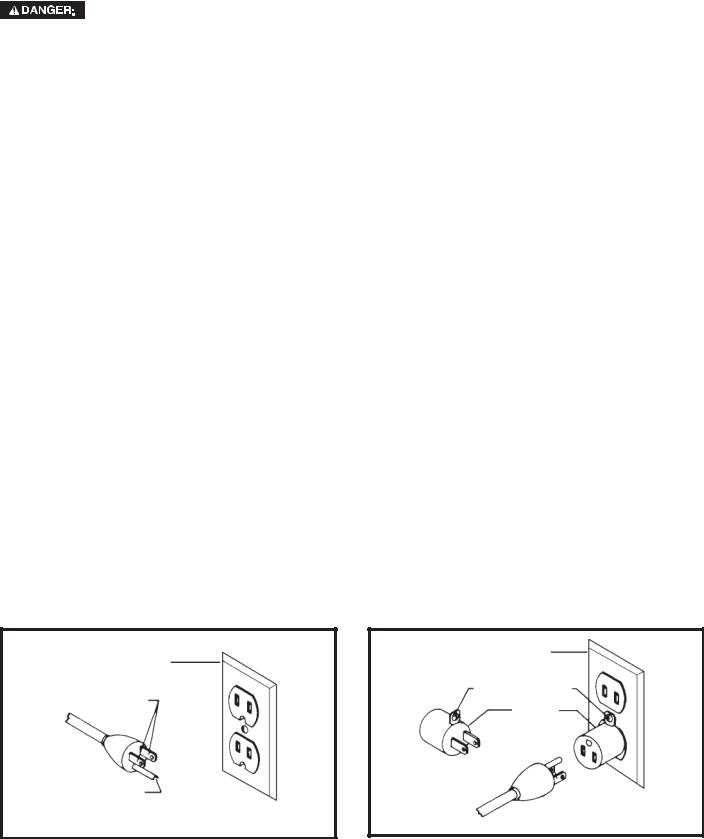
Use only 3-wire extension cords that have 3-prong grounding type plugs and matching 3-conductor receptacles that accept the machine’s plug, as shown in Fig. A.
Repair or replace damaged or worn cord immediately.
2.Grounded, cord-connected machines intended for use on a supply circuit having a nominal rating less than 150 volts:
If the machine is intended for use on a circuit that has an outlet that looks like the one illustrated in Fig. A, the machine will have a grounding plug that looks like the plug illustrated in Fig. A. A temporary adapter, which looks like the adapter illustrated in Fig. B may be used to connect this plug to a matching 2-conductor receptacle as shown in Fig. B, if a properly grounded outlet is not available. The temporary adapter should be used only until a properly grounded outlet can be installed by a qualified electrician. The green-colored rigid ear, lug, and the like, extending from the adapter must be connected to a permanent ground such as a properly grounded outlet box. Whenever the adapter is used, it must be held in place with a metal screw.
NOTE: In Canada, the use of a temporary adapter is not permitted by the Canadian Electric Code.
 In all cases, make certain that the receptacle in question is properly grounded. If you are not sure, have a qualified electrician check the receptacle.
|
GROUNDED OUTLET BOX |
||
GROUNDED OUTLET BOX |
|
|
|
CURRENT |
GROUNDING MEANS |
||
|
|
|
|
CARRYING |
|
|
|
|
ADAPTER |
|
|
PRONGS |
|
|
|
|
|
|
|
|
|
|
|
GROUNDING BLADE
IS LONGEST OF THE 3 BLADES
Fig. A |
Fig. B |
5
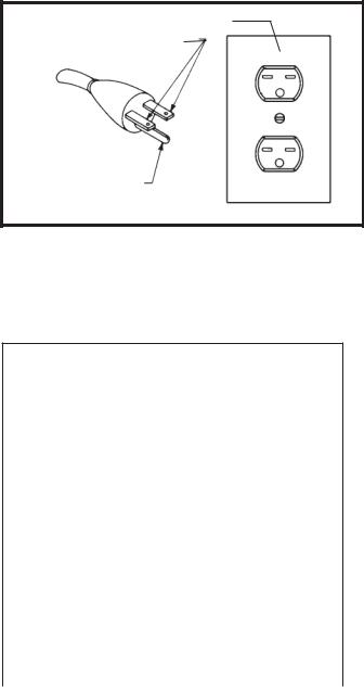
3.Grounded, cord-connected machines intended for use on a supply circuit having a nominal rating between 150
-250 volts, inclusive:
If the machine is intended for use on a circuit that has an outlet that looks like the one illustrated in Fig. C, the machine will have a grounding plug that looks like the plug illustrated in Fig. C. Make sure the machine is connected to an outlet having the same configuration as the plug. No adapter is available or should be used with this machine. If the machine must be re-connected for use on a different type of electric circuit, the re-connection should be made by qualified service personnel; and after re-connection, the machine should comply with the National Electric Code and all local codes and ordinances.
4.Permanently connected machines:
If the machine is intended to be permanently connected, all wiring must be done by a qualified electrician and conform to the National Electric Code and all local codes and ordinances.
*THREE PHASE OPERATION: Three phase machines are not supplied with a power cord and must be permanently connected to a building’s electrical system. Extension cords can’t be used with a three phase machine.
*LVC MAGNETIC MOTOR CONTROL: If you purchased a machine that has a Low Voltage Magnetic Motor Control System, refer to its instruction manual for installation guidance.
EXTENSION CORDS
 Use proper extension cords. Make sure your extension cord is in good condition and is a 3-wire extension cord which has a 3-prong grounding type plug and matching receptacle which will accept the machine’s plug. When using an extension cord, be sure to use one heavy enough to carry the current of the machine. An undersized cord will cause a drop in line voltage, resulting in loss of power and overheating. Fig. D-2 shows the correct gauge to use depending on the cord length. If in doubt, use the next heavier gauge. The smaller the gauge number, the heavier the cord.
GROUNDED OUTLET BOX
CURRENT
CARRYING
PRONGS
GROUNDING BLADE
IS LONGEST OF THE 3 BLADES
Fig. C
MINIMUM GAUGE EXTENSION CORD
RECOMMENDED SIZES FOR USE WITH STATIONARY ELECTRIC MACHINES
|
|
Total |
|
Ampere |
|
Length of |
|
|
Cord in |
Gauge of Extension |
|
|
|
||
Rating |
Volts |
Feet |
Cord |
0-6 |
240 |
up to 50 |
18 AWG |
0-6 |
240 |
50-100 |
16 AWG |
0-6 |
240 |
100-200 |
16 AWG |
0-6 |
240 |
200-300 |
14 AWG |
6-10 |
240 |
up to 50 |
18 AWG |
6-10 |
240 |
50-100 |
16 AWG |
6-10 |
240 |
100-200 |
14 AWG |
6-10 |
240 |
200-300 |
12 AWG |
10-12 |
240 |
up to 50 |
16 AWG |
10-12 |
240 |
50-100 |
16 AWG |
10-12 |
240 |
100-200 |
14 AWG |
10-12 |
240 |
200-300 |
12 AWG |
12-16 |
240 |
up to 50 |
14 AWG |
12-16 |
240 |
50-100 |
12 AWG |
12-16 |
240 |
GREATER THAN 50 FEET NOT RECOMMENDED |
|
Fig. D-2
6
FUNCTIONAL DESCRIPTION
FOREWORD
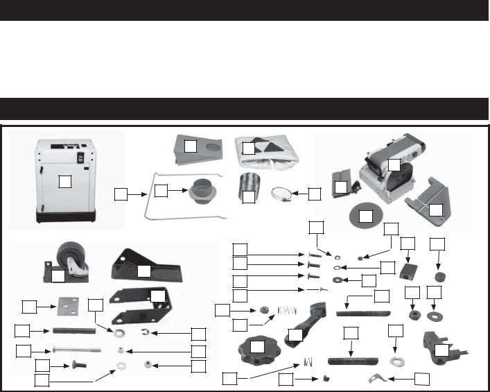
The Delta Model 31-735 is an abrasive finishing machine. This unit includes two tilting tables, a 4-1/2" arbor pulley, a V- belt, a 100-grit aluminum oxide belt, and an 80-grit aluminum oxide disc.
NOTICE: The manual cover illustrates the current production model. All other illustrations contained in the manual are representative only and may not depict the actual labeling or accessories included. These are intended to illustrate technique only.
CARTON CONTENTS
|
|
|
2 |
5 |
|
|
|
|
|
|
|
|
|
|
|
|
8 |
|
|
|
1 |
|
4 |
|
|
9 |
|
|
|
|
|
3 |
6 |
7 |
|
|
|
||
|
|
|
|
|
|
||||
|
|
|
|
|
|
|
|||
|
|
|
|
|
|
|
10 |
|
11 |
|
|
|
|
|
|
|
|
|
|
|
|
|
|
|
24 |
|
25 |
|
|
|
|
|
|
24 |
|
|
|
45 |
46 |
|
|
|
|
|
|
|
|
|
|
|
|
|
13 |
27 |
|
|
28 |
|
|
|
12 |
|
|
|
|
|
|
||
|
|
29 |
|
|
30 |
|
|
||
|
|
|
|
|
|
|
|||
|
|
|
|
|
|
|
|
||
|
|
|
15 |
31 |
|
|
35 |
36 |
37 |
14 |
|
17 |
|
|
|
|
|||
|
|
32 |
|
|
|
|
|
||
|
|
|
|
|
|
|
|
|
|
16 |
|
|
|
33 |
|
40 |
41 |
|
|
|
|
|
18 |
34 |
|
|
|||
19 |
|
|
|
20 |
38 |
|
|
|
42 |
|
|
|
|
|
|
|
|||
|
21 |
|
|
23 |
|
|
|
|
|
|
22 |
|
|
39 |
43 |
|
|
44 |
|
1. |
Cabinet |
17. |
1/2" Flat Washer (2) |
33. |
1-3/16" Spring |
2. |
Dust Baffle |
18. |
Retaining Ring (2) |
34. |
Ratchet Lever |
3. |
Bag Hanger |
19. |
5/16-18x4" Hex Head Screw |
35. |
3/8-16x3½" Stud |
4. |
Dust Chute |
20. |
5/16-18 Lock Nut |
36. |
3/8-16 Hex Nut |
5. |
Dust Bag |
21. |
3/8-16x1" Carriage Head Bolt (3) |
37. |
3/8 Flat Washer |
6. |
Hose (2) |
22. |
3/8" Flat Washer (3) |
38. |
Disc Table Lock Handle (2) |
7. |
Hose Clamp (5) |
23. |
3/8-16 Hex Nut (3) |
39. |
1/2" Spring (2) |
8. |
Belt / Disc Sander |
24. |
1/4-20x5/8" Flat Head Screw (4) |
40. |
7/16-18x3" Stud (2) |
9. |
Belt Sanding Table |
25. |
1/4" Flat Washer (4) |
41. |
7/16" Flat Washer (2) |
10. |
Abrasive Disc |
26. |
1/4-20 Hex Nut (4) |
42. |
Disc Table Clamp (2) |
11. |
Disc Sanding Table |
27. |
5/16-18x1/2" Hex Head Screw (4) |
43. |
1/4-20x1/4" Round Head Screw |
12. |
Caster |
28. |
5/16" Lockwasher (4) |
44. |
Pointer |
13. |
Foot Lever |
29. |
#10-32x3/4" Button Head Screw (4) |
45. |
Circle Sanding Stop Block |
14. |
Bracket |
30. |
#10 Flat Washer (4) |
46. |
Circle Sanding Guide Pin |
15. |
Pivot Bracket |
31. |
M4-0.7x12mm Sheet Metal Screw (4) |
|
|
16. |
1/2x4" Pin |
32. |
3/8-16 Lock Nut |
|
|
UNPACKING AND CLEANING
Carefully unpack the machine and all loose items from the shipping container(s). Remove the rust-preventative oil from unpainted surfaces using a soft cloth moistened with mineral spirits, paint thinner or denatured alcohol.
 Do not use highly volatile solvents such as gasoline, naphtha, acetone or lacquer thinner for cleaning your machine.
After cleaning, cover the unpainted surfaces with a good quality household floor paste wax.
7
ASSEMBLY
 For your own safety, do not connect the machine to the power source until the machine is completely assembled and you read and understand the entire instruction manual.
ASSEMBLY TOOLS REQUIRED
1/4" Wrench |
Adjustable Wrench |
5/16" Wrench |
Pliers |
3/8" Wrench |
Phillips Screwdriver |
ASSEMBLY TIME ESTIMATE
Assembly for this machine takes approximately 1 to 2 hours.
ATTACHING THE CASTER ASSEMBLY TO THE MOTOR CABINET
 Disconnect the machine from the power source!
1.Place the motor cabinet on its side.
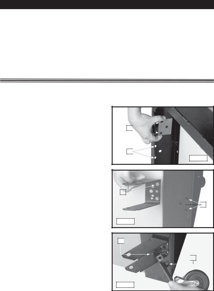
2.Align the three holes in the bracket (B) Fig. 1 with the three holes in the inside of the base (C).
3.Insert a 3/8-16x1" carriage head bolt through the hole in the bracket (B) Fig. 1 and through the base (C).
4.Place the pivot bracket (D) Fig. 2 on the screw and aligned with the other holes (C).
5.Place a 3/8" flat washer on the screw. Thread a 3/8-16 hex nut on the screw and hand-tighten.
6.Repeat this process for the two remaining holes.
7.Tighten all of the hardware securely.
8.Align the two holes in the caster assembly (E) Fig. 3 with the two holes (F) in the pivot bracket.
B 
C 
Fig. 1
D 

 C
C
Fig. 2
F 


 E
E
Fig. 3
8

9.Insert a 5/16-18x4" hex head screw (G) Fig. 4 through the hole (F) Fig. 3, the two holes (E) in the caster assembly, and the other hole (F) in the pivot bracket. Thread a 5/16-18 lock nut on the screw. Tighten securely.
10.Align the two holes (H) Fig. 5 in the foot lever with the two holes (J) in the pivot bracket.
G |
|
|
|
|
||
|
|
|
|
|
H |
|
|
|
|
|
|
|
J |
|
|
|
|
|
|
|
|
|
|
|
|
Fig. 5 |
|
|
Fig.4 |
|
|
|||
|
|
|
|
|
|
|
|
|
|
|
|
|
|
|
|
|
|
|
|
|
11. |
Attach the foot lever (N) Fig. 6 to the pivot bracket (O), |
|
M |
|
O |
|
|
|
using 1/2"x4" pin (M), two 1/2" flat washers (K), and |
|
|
|
|
|
|
|
|
|
|
|
|
||
|
|
P |
|
|
|
||
|
two retaining rings (P) Fig. 6. |
|
|
|
|
||
12. |
Stand the motor cabinet upright. |
|
|
|
|
||
INSTALLING THE DUST BAFFLE |
|
|||
|
|
|
N |
|
|
|
|
K |
|
|
|
|
||
|
|
|
||
|
|
|
Disconnect the machine from the |
|
|
|
|
power source! |
|
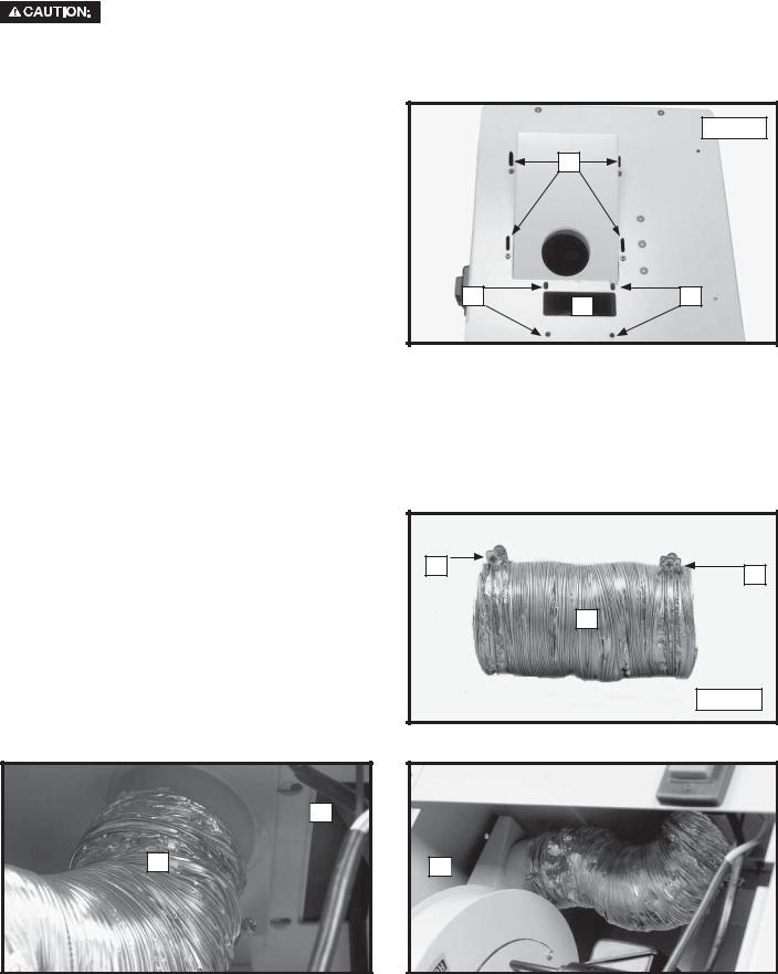
1.Remove the two screws (A) Fig. 7 and loosen the two
|
other screws (B). |
|
|
|
2. |
Remove the back cover of the cabinet (C) Fig. 7. |
P |
|
|
|
Fig. 6 |
|||
3. |
Loosen the four nuts (D) Fig. 8. Lower the motor. |
|
|
4.Insert the dust baffle (F) Fig. 9 through the front of the cabinet.
5.Align the four slots in the dust baffle with the four holes (G) Fig. 10 in the top of the cabinet.
6.Insert a 1/4-20 x 5/8" flat head screw through the hole (G) Fig. 10 in the top of the cabinet and the dust baffle. Place a 1/4" flat washer on the screw. From the inside of the cabinet, thread a 1/4-20 hex nut on the screw. Tighten securely.
7.Repeat for the three remaining holes in the top of the cabinet and the dust baffle.
|
|
|
|
|
|
|
|
|
|
|
|
|
|
|
|
A |
|
|
|
|
|
|
|
||
|
|
|
|
|
|
|
|
|
D |
|
||
|
|
|
|
|
|
|
|
|||||
|
C |
|
|
|
|
|
|
|||||
|
|
|
|
|
|
|
|
|
|
|
|
|
|
|
|
|
|
|
|
|
|
|
|||
|
|
|
B |
|
|
|
|
|
|
|
||
|
|
|
|
|
|
|
|
|
|
|
|
|
|
|
|
|
|
Fig. 7 |
|
|
|
|
|
Fig. 8 |
|
|
|
|
|
|
|
|
|
|
|
|
|
|
|
|
|
|
|
|
|
|
|
|
|
|
|
CABINET
TOP
G
F
Fig. 9 |
|
Fig. 10 |
9
ATTACHING THE SANDING UNIT TO THE CABINET
The belt/disc sander is heavy. Use two or more people to lift the unit to the top of the cabinet.


 Disconnect the machine from the power source!
1. Place the sanding unit on top of the cabinet.
NOTE: Insert the sander drive belt through the hole (A) FIG. 11.
2.Place a 5/16" lock washer on a 5/16-18 x 1/2" hex head screw. From inside the cabinet, insert the screw through one of the holes (B) Fig. 11, and into the threaded hole in the sanding unit. Tighten the screw securely.
3.Repeat this process for the three remaining holes (B) Fig. 11.
4.Place a #10 washer on a #10-32 x 3/4" button-head screw. From the inside of the cabinet, insert the screw through one of the holes (C) Fig. 11 in the dust baffle and cabinet and into the threaded hole in the sanding unit. Tighten the screw securely.
5.Repeat for the three remaining holes.
|
|
Fig. 11 |
|
C |
|
B |
A |
B |
|
|
INSTALLING THE DUST COLLECTOR INTAKE HOSE
 Disconnect the machine from the power source!
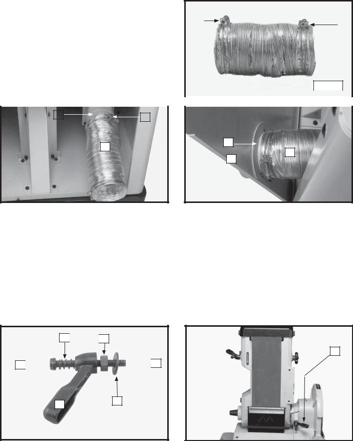
1.Place a hose clamp (A) Fig. 12 on each end of hose
2.Slide one end of hose (B) Fig. 13 over the hose port
(C)on the dust baffle inside the cabinet. Secure it with the hose clamp.
3.Slide the other end of the hose over the fan intake port (F) Fig. 14 inside the cabinet. Secure it with the hose clamp.

 C
C
B
A
A
B
Fig. 12
F 

Fig. 13 |
|
Fig. 14 |
10
INSTALLING THE BELT ON THE MOTOR
 Disconnect the machine from the power source!
1.Remove the two screws (A) Fig. 15 from the top of the sanding unit and remove the plate (B).
2.Check to see that the belt (C) Fig. 16 is in the groove of the pulley (D) of the sanding unit.
3.Lift the motor (F) Fig. 17 and place the belt (C) on the motor pulley (G).
4.Slowly lower the motor (F) Fig. 17 to apply pressure to the belt (C).
5.Secure the motor with the hex nuts (H) Fig. 18.
A
B
Fig. 15
C
F
G
Fig. 17
INSTALLING THE DUST CHUTE
D

 C
C
Fig. 16
H
Fig. 18


 Disconnect the machine from the power source!
1.Insert the dust chute (A) Fig. 19 through the inside hole of the cabinet back panel (B) that was removed earler.
2. |
Align the four holes in the dust chute (A) Fig. 19 with |
|
|
A |
|
the four holes in the back panel (B). Insert an M4- |
|
|
|
|
0.7 x 12mm sheet metal screw through the back |
B |
|
|
|
panel (B). Thread the screw into the dust chute. |
|
|
|
|
Tighten securely. |
|
|
|
3. |
Repeat for the three remaining holes. |
|
|
|
Fig. 19
11
INSTALLING THE DUST COLLECTOR OUT-TAKE HOSE
 Disconnect the machine from the power source!
1.Place a hose clamp (A) Fig. 20 on each end of the out-take hose (B).
2. |
Slide one end of hose (B) Fig. 21 over the dust |
A |
|
|
|
|
|
|
|
A |
|||
|
collector out-take port (C) and secure it with the |
|
|
|
||
|
|
|
|
|
||
|
hose clamp (A). |
|
|
|
|
|
3. |
Slide the other end of the hose (B) Fig. 22 over the |
|
|
|
|
|
|
|
B |
|
|
||
|
dust chute (D) on the inside of the back panel of the |
|
|
|
||
|
|
|
|
|
|
|
|
cabinet. Secure it with the hose clamp (A). |
|
|
|
|
|
4.Replace the back panel of cabinet that was removed in STEP 2 of the section “INSTALLING THE DUST
BAFFLE”. |
|
|
|
|
|
|
Fig. 20 |
|
|
|
|
|
|
|
|
|
|
|
|
|
|
|
|
|
|
|
|
|
|
|
|
|
|
|
|
|
C |
|
|
|
|
|
|
|
|
|
A |
|
|
|
|
|
|
|
|
|
|
|||||
D
B
B
A 
Fig. 21 |
|
|
|
Fig. 22 |
|
|
|
|
BELT SANDER TABLE


 Disconnect the machine from the power source!
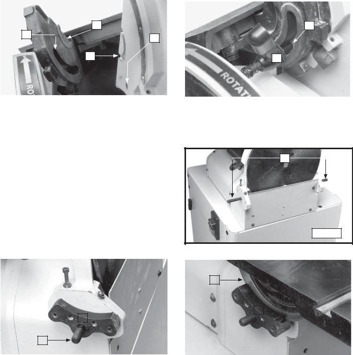
1. Thread a 3/8-16 lock nut (A) Fig. 23 on a 3/8-16 x 3-1/2" stud (B).
NOTE: Thread the lock nut (A) FIG. 23 flush or slightly below the threads on the stud.
2.Place a 1-3/16" spring (C) Fig. 23 on the stud (B).
3.Insert the sanding ratchet lever (D) Fig. 23 on the stud (B).
4.Thread a 3/8-16 hex nut (E) Fig. 23 on the stud (B).
5.Place a 3/8" flat washer (F) Fig. 23 on the stud (B).
6.Loosen the ratchet lever (H) Fig. 24.
7.Raise the belt sander to the the horizontal position (Fig. 24).
8.Tighten the lock knob (H) Fig. 24.
C 
 E
E
H
A 


 B
B
F
D
Fig. 23 |
|
Fig. 24 |
12
9.Align the sanding table guide (J) Fig. 25 with cutout (K) on the side of the sanding belt frame.
10.Thread the sanding ratchet lever/stud assembly (L) Fig. 26 through the sanding table slot (N) Figs. 25 and 26, and into the tapped hole (M) Fig. 26 in the side of the sanding frame.
NOTE: Thread the sanding table ratchet lever/stud assembly approximately 1/2" into the sanding table frame.
11.Use the sanding table ratchet lever to thread the hex nut (E) Fig 23 against the sanding table to hold the sanding table in place.
NOTE: You can reposition the ratcher lever (A) Fig. 23 by pulling out on the handle and moving it on the nut located underneath the hub.
|
|
J |
|
|
|
|
|
|
|
|
|
|
|
N |
|
|
N |
M |
|
|
|
|
|
|
|
|
|
|
|
|
|
|
|
K |
|
|
|
|
L |
|
|
|
|
|
|
|
|
|
|
|
|
|
|
|
|
|
Fig. 25 |
|
|
|
|
Fig. 26 |
|
|
|
|
|
|
|
|
|
|
|
|
|
|
|
|
|
 RISK OF PERSONAL INJURY. Position the edge of the table a maximum of 1/16" from the sanding belt to prevent trapping the work or your fingers between the belt and the table.


 Disconnect the machine from the power source!
A
1. Thread the 7/16 x 3" studs (A) Fig. 27 into the side of the disc sander.
2. Place the clamp (B) on one of the studs (A) Fig. 28. Repeat for the other stud.
3.Align the table lock rail (C) Fig. 29 on the disc sander table, with the grooves in the table clamps
(B).
Fig. 27
|
|
|
|
|
|
|
|
C |
|
|
|
|
|
|
|
|
|
|
|
|
B |
|
|
|
|
|
B |
|
|
|
|
|
|
||
|
|
|
|
|
|
|
|
|
|
|
|
|
A |
|
|
|
|
|
|
|
|
|
|
|
|
|
|
Fig. 28 |
|
|
|
|
Fig. 29 |
|
|
|
|
|
|
|
|
|
|
|
|
||
|
|
|
|
|
|
|
|
|
|
|
|


 Position the edge of the table a maximum of 1/16" from the sanding disc to prevent trapping the work or your fingers between the table and the disc.
13
4.Place a 7/16" flat washer (C) Fig. 30 on each stud, then a 1/2" spring (D).
5.Thread the lock handle (E) on the right side stud. Tighten securely to hold the disc sander table in place.
6.Align the hole in the pointer (A) Fig. 31 with the tapped hole (D) in the the left side table clamp.
7.Thread a 1/4-20 x 1/4" round head screw (B) Fig. 31 through the hole in the pointer and into the table clamp. Tighten securely.
8.Thread the disc table lock handle (E) Fig. 30 on the left side stud. Tighten it securely to hold the disc sander table in place.
D
A
B
D
E 

Fig. 30 |
C |
Fig. 31 |
ATTACHING THE ABRASIVE DISC


 Disconnect the machine from the power source!
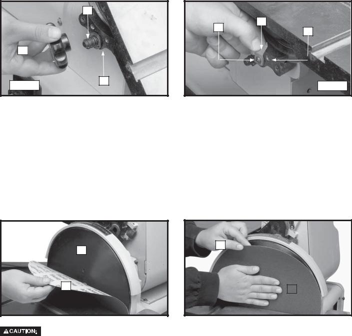
1.Ensure that the disc assembly (A) Fig. 32 is clean, dry, and free of oil or grease.
2.Separate and fold back approximately half of the adhesive backing from the abrasive disc (C) Fig. 32. Place the abrasive disc (C), with the backing, between the table, and disc assembly (A). Press the top half of the adhesive disc (C) in position.
3.Rotate the disc assembly (A) Fig. 33. Remove the paper backing from the abrasive disc (C) and firmly press the disc on the disc assembly (A).
A 
A
C |
|
|
|
|
|
|
C |
|
|
||
|
|
|
|
||
|
|
|
|
|
|
|
Fig. 32 |
|
|
|
Fig. 33 |
Ensure that the abrasive disc (C) is securely in position before applying power to the machine.
 RISK OF PERSONAL INJURY. Position the edge of the table a maximum of 1/16" from the sanding belt to prevent trapping the work or your fingers between the belt and the table.
14
ATTACHING THE DUST COLLECTOR BAG


 Disconnect the machine from the power source!
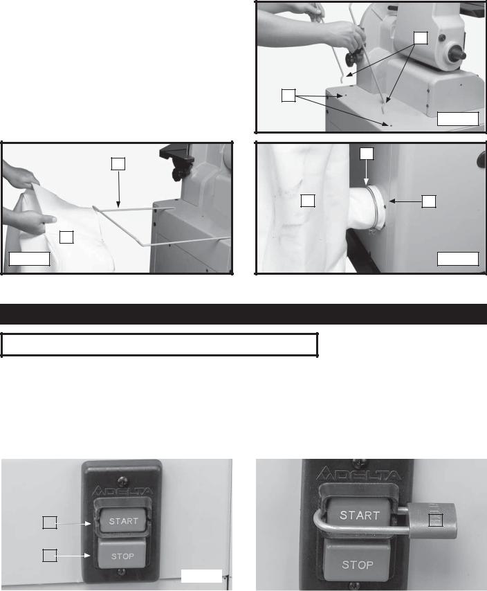
1.Insert the dust collector bag hanger (A) Fig. 34 in the two holes (B) in the top of the cabinet.
2.Place the end of the dust collector bag (C) Fig. 35 over the dust collector hanger (A).
3.Place a hose clamp (D) Fig. 36 over the intake port of the dust collector bag (C). Slide the intake port of the dust collector bag over the dust chute (E). Tighten the hose clamp around both the bag (C) and the chute (E).
A
C
Fig. 35
|
A |
B |
|
|
Fig. 34 |
|
D |
C |
E |
Fig. 36
NOTE: Review the section “DUST PORT COVER” before operating the dust collector.
OPERATION
OPERATIONAL CONTROLS AND ADJUSTMENTS
STARTING AND STOPPING THE UNIT
 Make sure that the switch is in the “OFF” position before plugging cord into outlet. Do not touch the plug’s metal prongs when unplugging or plugging in the cord.
To start the machine, push the “START” button (A) Fig. 37. To stop the machine, push the “STOP” button (B).
IMPORTANT: When the machine is not in use, the switch should be locked in the "OFF" position using a padlock (C) Fig. 38, with a 3/16" diameter shackle to prevent unauthorized use.
|
|
|
|
|
|
|
|
|
|
|
|
|
|
|
|
|
|
|
|
C |
|
|
|
|
A |
|
|
|
|
|
|
|
|||
|
|
|
|
|
|
|
|
|
|
||
|
|
|
|
|
|
|
|
|
|
||
|
B |
|
|
|
|
|
|
|
|
|
|
|
|
|
|
|
|
|
|
|
|
|
|
|
|
|
|
Fig. 37 |
|
|
|
|
|
Fig. 38 |
|
|
|
|
|
|
|
|
|
|
|
|
|
 In the event of a power outage (a breaker or fuse trip), always move the switch to the “OFF” position until the main power is restored.
15
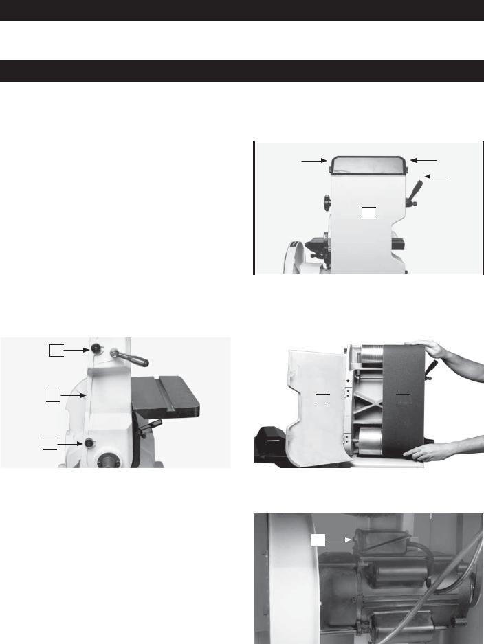
ADJUSTING THE TENSION AND TRACKING OF THE SANDING BELT
 Your machine is shipped without belt tension. Before operating the machine, tension the belt properly and ensure that the belt is tracking correctly.
 Disconnect the machine from the power source!
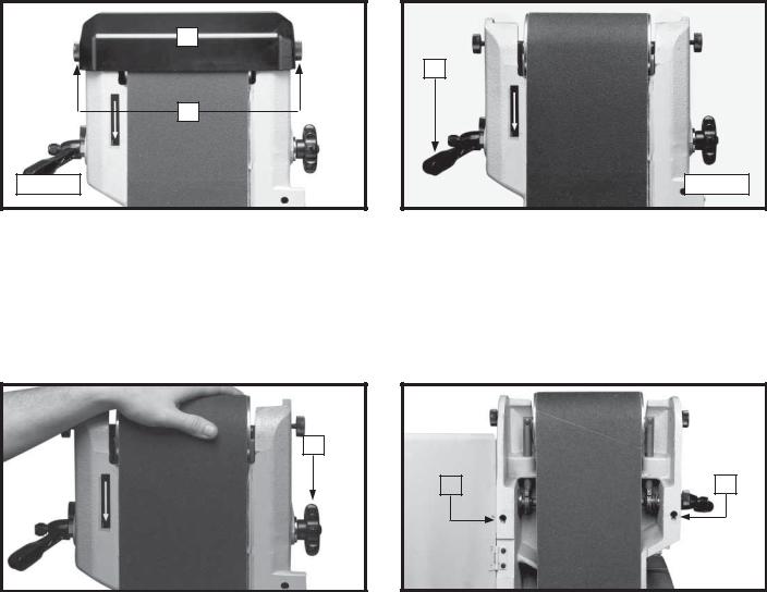
1.Loosen the two lock knobs (A) Fig. 39 and remove the top cover (B).
2.Turn the belt tension handle (C) Fig. 40 counter-clockwise to increase belt tension. Correct tension is determined by its flatness on the platen with just enough tension to take the curl out of the belt.
|
B |
|
C |
|
A |
Fig. 39 |
Fig. 40 |
3.Rotate the belt by hand and tighten or loosen the tracking knob (E) Fig. 41 until the belt is running true on the pulleys.
4.Jog the machine "ON" and "OFF" to confirm that the belt is tracking properly. If the belt moves toward either side, turn the tracking knob (E) Fig. 41 clockwise to direct the belt toward the adjusting screw or counter-clockwise to direct it in the opposite direction.
5.You can make your final adjustment with the motor running. This adjustment is usually very slight. After the belt is tracking properly, disconnect the machine from the power source, and replace the top cover.
E
F |
|
G |
Fig. 41 |
|
|
|
Fig. 42 |
|
|
|
|
NOTE: After a long period of time, you may have to make adjustments to the tension and tracking of the sanding belt. If the belt will not hold its tension, tighten the set screw (G) Fig. 42. If the belt will not hold its tracking, tighten the set screw (F) Fig. 42. Make only small adjustments. Over-tightening will lock the tension lever and/or the tracking knob.
16
SETTING THE TABLE 90° TO THE BELT
 Disconnect the machine from the power source!
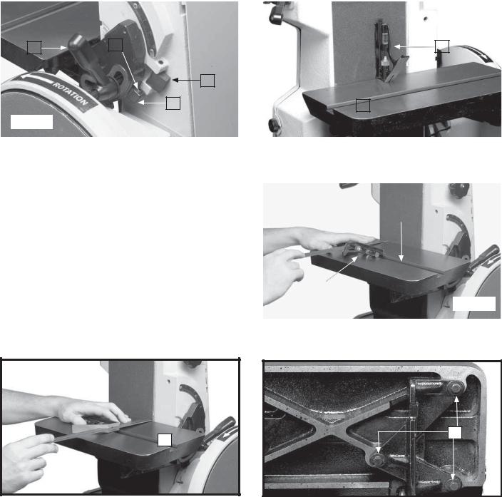
1.Loosen the table-tilting ratchet lever (A) Fig. 43. Turn the stop (B) to the left and rotate the table (C) Fig. 44 until the trunnion (D) Fig. 43 contacts the stop (B). Tighten the lock handle (A).
NOTE: The lock handle (A) is spring-loaded and can be repositioned by pulling out the handle, moving it, and letting it spring back into position.
2.Place a square (E) Fig. 44 on the table against the belt. See if the table is 90° to the belt.
3.To adjust, loosen the handle (A) Fig. 43. Turn the adjusting screw (F) in or out until table is 90° to the belt.
4.Tighten the lock handle (A) Fig. 43.
5.The adjusting screw (F) Fig. 43 ensures that the belt table can rapidly return to the 90° position after the table has been tilted.
6.Adjust the pointer.
7.Follow the same procedure when adjusting the table to stop at the 45° position.
|
|
|
|
|
|
|
|
|
|
|
|
|
|
|
|
|
|
|
|
|
|
|
|
F |
|
|
|
|
|
|
|
|
|
|
|
|
|
|
|
|
|
|
|
|
|
|
|
|
|
|
|
E |
|
|
|
|
|
|
A |
|
|
|
|
|
|
|
|
|
|
||||||
|
|
|
|
|
|
|
|
|
|
|
||||||||
|
|
|
|
|
|
|
|
|
|
|
|
|
|
|
|
|
|
|
|
|
|
|
|
|
|
|
|
|
|
|
|
|
|
|
|
|
|
|
|
|
|
|
|
|
|
|
B |
|
|
|
|
|
|
|
|
|
|
|
|
|
|
|
|
|
|
|
|
|
|
|
|
|
|||
|
|
|
|
|
|
|
D |
|
|
|
|
|
|
|
|
|||
|
|
|
|
|
|
|
|
|
|
|
|
C |
|
|
|
|||
|
|
|
|
|
|
|
|
|
|
|
|
|||||||
|
|
|
|
|
|
|
|
|
|
|
|
|
|
|
|
|
|
|
|
Fig. 43 |
|
|
|
|
|
|
|
|
|
|
|
|
|
Fig. 44 |
|
||
|
|
|
|
|
|
|
|
|
|
|
|
|
|
|
|
|
|
|
|
|
|
|
|
|
|
|
|
|
|
|
|
|
|
|
|
|
|
SETTING THE MITER GAUGE SLOT PARALLEL TO THE SANDING BELT
 Disconnect the machine from the power source!
1. Position the table (A) (Figs. 45 and 46) 90° to the |
|
|
|
|
|
|
|
|
|
|
|
|
|
|
|
|
|
|
|
belt. Place a square (B) in the miter gauge slot with |
|
|
|
|
|
|
|
|
|
the blade (C) of the square touching the sanding |
|
|
|
|
|
|
|
|
|
|
|
|
C |
|
|
|
|
|
|
belt. Check the opposite end of the belt (Fig. 46) to |
|
|
|
|
|||||
|
|
|
|
|
|
|
|
|
|
see if the miter gauge slot is parallel to the belt. |
|
|
|
|
|
|
|
|
|
2. To adjust, loosen the three screws (E) Fig. 47 |
|
|
|
|
|
|
|
|
|
underneath the table. Move the table (A) until the |
|
|
|
|
|
A |
|
|
|
miter gauge slot is parallel to the sanding belt. |
|
|
|
|
|
|
|
|
|
Tighten the three screws (E). |
|
B |
|
|
|
|
|
|
|
|
|
|
|
|
|
|
|
|
|
NOTE: When making this adjustment, tighten the table |
|
|
|
|
|
|
|
Fig. 45 |
|
lock lever. |
|
|
|
|
|
|
|
|
|
|
|
|
|
|
|
|
|
|
|


 Maintain a maximum distance of 1/16" between the sanding belt and the table.
E
A
Fig. 46 |
|
Fig. 47 |
17
CHANGING THE POSITION OF THE SANDING ARM
 Disconnect the machine from the power source!
1.You can use the sanding arm in any angle from the vertical position (Fig. 48) to the horizontal position (Fig. 49). Loosen the lock lever (B), position the arm (A) to the desired angle, and tighten the lock lever (B).
2.You can remove the top idler pulley cover (C) Figs. 48 and 49 to clear the workpiece when you sand in the horizontal position. For a long workpiece, lower the deflector plate (D) to clear the workpiece. Raise the deflector plate (D) to deflect saw dust when sanding a short workpiece.
NOTE: With the sanding arm (A) in the horizontal position (Fig. 49), use the table (E) or the accessory backstop to support the work.
|
|
|
|
|
|
|
|
|
|
|
|
|
|
|
|
|
|
|
|
|
|
|
|
|
|
|
|
|
C |
|
|
|
|
|
|
|
|
|
|
|
|
|
|
|
|
|
|
|
|
|
|
|
|
|
|
|
|
|
|
|
|
|
|
|
|
|
|
|
|
|
|
|
|
|
|
|
|
|
|
|
|
|
|
|
|
|
|
C |
|
|
|
|
|
|
|
|
|
|
|
|
|
|
|
|
|
|
|
|
|
|
|
|
|
|
|
|
E |
|
|
|
|
|
||
|
|
|
|
|
|
|
|
|
|
|
|
|
|
|
|
|
||||||||
|
|
|
|
A |
|
|
|
|
|
|
|
|
|
|
|
|
|
|
|
|
|
|
|
|
|
|
|
|
|
|
|
|
|
|
|
|
|
|
|
|
|
|
|
|
|
|
|
||
|
|
|
|
|
|
|
|
|
|
|
|
|
|
|
|
|
|
|
|
B |
|
|
||
|
|
|
|
|
|
|
|
|
|
|
|
|
|
|
|
|
|
|
|
|
|
|
||
|
|
|
|
|
|
|
|
|
|
|
|
|
|
|
|
|
|
|
|
|
|
|
|
|
|
|
|
|
|
|
|
|
|
|
|
|
|
|
|
|
|
|
|
|
|
|
|
|
|
|
|
|
|
|
|
|
E |
|
|
|
|
|
|
|
|
|
|
|
|
|
|
|
|
|
|
|
|
|
|
|
|
|
|
|
|
|
|
|
A |
|
|
|
|
|
|
|
|
|
|
|
|
|
|
|
|
|
|
|
|
|
|
|
|
|
|
|
D |
|
|
|
|
|
||
|
|
|
|
|
|
|
|
B |
|
|
|
|
|
|
|
|
|
|
|
|
|
|||
|
|
|
|
|
|
|
|
|
|
|
|
|
|
|
|
|
|
|
|
|||||
|
|
|
|
|
|
|
|
|
|
|
|
|
|
|
|
|
|
|
|
|
|
|
||
|
|
|
|
|
|
|
|
|
|
|
|
|
|
|
|
|
|
|
|
|
|
|
|
|
|
|
|
|
|
|
|
|
|
|
|
|
|
|
|
|
|
|
|
|
|
|
|
|
|
|
Fig. 48 |
|
|
|
|
|
|
|
|
|
|
|
|
|
|
|
|
|
|
|
|
Fig. 49 |
|
|
|
|
|
|
|
|
|
|
|
|
|
|
|
|
|
|
|
|
|
|
|
|
|
|
|
|
|
|
|
|
|
|
|
|
|
|
|
|
|
|
|
|
|
|
|
|
|
|
|
|
SETTING THE SANDING DISC TABLE 90° TO THE DISC
 Disconnect the machine from the power source!
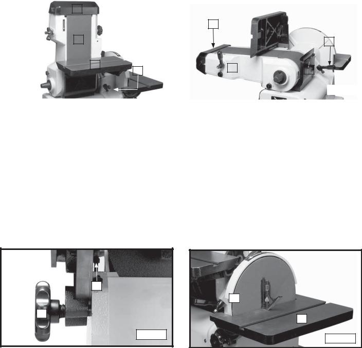
1.Loosen the two disc table lock handles (the left one is shown at (A) Fig. 50 and move the table (B) Fig. 51 until It contacts the table stop screw (C) Fig. 50 on the left side of the table. Tighten the lock handles.
2.Place a square (E) Fig. 51 on the table and against the sanding disc. See if the table is 90° to the disc.
3.To adjust, loosen the lock handles (A) Fig. 50 and tighten or loosen the table stop screw (C) Fig. 50.
4.Adjust the sanding disc table pointer.
TILTING THE DISC SANDER TABLE
 Disconnect the machine from the power source!
To tilt the table, loosen the disc table lock handles, one of which is shown at (A) Fig. 50, and move the table to the desired angle and tighten the lock handles.
C
E 

A
B
Fig. 50
Fig. 51
18
SETTING THE DISC TABLE MITER GAUGE SLOT PARALLEL TO THE SANDING DISC
 Disconnect the machine from the power source!
1.With the table (A) Fig. 52 positioned 90° to the disc, place a square (B) in the miter gauge slot with the blade of the square touching the sanding disc.
2.Mark where the square (B) Fig. 52 contacts the disc with a pencil. Measure the distance from the disc to the miter gauge slot.
3.Rotate the disc 180°. Use a square to check the distance between the miter gauge slot and the mark on the disc made in STEP 3. The distance should be the same.
4.To adjust, loosen the four screws on the table trunnions, two of which are shown at (D) Fig. 53. Adjust the table until the miter gauge slot is parallel to the disc. Tighten the four screws (D)
NOTE: When making this adjustment, tighten the table lock handle.
D
B
A
Fig. 52 |
|
|
|
Fig. 53 |
|
|
|
|


 Maintain a maximum distance of 1/16" between the sanding disc and the table.
ADJUSTING THE DUST PORT COVER
The abrasive finishing machine is equipped with a manually-operated dust port cover (A) Fig. 54 that can be adjusted to suit the sanding operation.
 Disconnect the machine from the power source!
1. If you are sanding with the disc, push in on the dust port cover (A) Fig. 54. 2 If you are sanding with the belt, pull the dust port cover (A) Fig. 55 outward.
A
A
Fig. 54 |
|
Fig. 55 |
19
MACHINE USE
ABRASIVE BELTS & DISCS - THEIR SELECTION AND USE
Delta supplies a wide range of belts and discs for use on your Belt and Disc Finishing Machine. You can use these belts and discs for a wide range of work on wood, metals, plastics and other materials. However, when you have a large amount of production work of one kind, refer to a coated-abrasive specialist for specific belt and disc recommendations.
You can process a wide variety of materials on a dry belt or disc. However, for professional quality or for production work, use a low, melting-point grease for cooler cutting, better finish, and longer belt life. Use a lubricant to grind aluminum to prevent "loading" of the belt or disc. This can also be true of other non-ferrous metals like soft brass and zinc.
Use a grease stick to the belt or disc to prevent "loading" of the belt on softer materials. When grinding steel or some kinds of plastic, use the grease stick to prevent over-heating of the workpiece. Many times a single belt can be used for both stock removal and for finish. Lubricate one-half of the belt with light grease for stock removal and the other half of the belt with a heavy grease for polishing to bring out a good finish. This can be done only when the parts are very small and do not have to be moved across the face of the belt.
When an abrasive belt smaller than 6" is desired, you can split the 6" belt. Turn the belt inside out and cut a slot in the belt at the desired width. Then tear the belt.
NOTE: Tear the belt a few inches at a time in one direction, then reverse your tearing action to reduce unraveling.
 For certain applications, a mist coolant attachment (not supplied by Delta) can be helpful. If the use of a mist coolant causes the abrasive belt to slip on the lower drive pulley, correct it by using a "tire" that can be made by wrapping the pulley with a piece of coated abrasive belt. Turn the grit to the outside. Use cement sparingly to avoid lumps under the "tire."
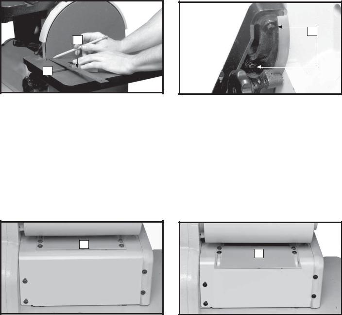
SURFACE OR EDGE SANDING WITH THE SANDING BELT
When surfacing (Fig. 56), or edge sanding (Fig. 57), use the sanding arm in the horizontal position. Use the table (A) Fig. 56 and Fig. 57 to prevent the workpiece from being carried along with the belt. Hold the workpiece firmly, keeping your fingers away from the sanding belt. Keep the end of the workpiece against the table and move it evenly across the sanding belt. Apply only enough pressure to allow the sanding belt to remove material. Use extra caution when sanding very thin pieces.
A
A
|
|
Fig. 57 |
|
Fig. 56 |
|||
|
|
20
SANDING INSIDE CURVES


 Disconnect the machine from the power source!
1.Loosen the two lock knobs (A) Fig. 58 and remove the top cover (B).
2.Inside curves can be sanded on the top sanding drum (Fig. 59).
B |
A |
Fig. 58 |
Replace the top cover (B) Fig. 58 when done.
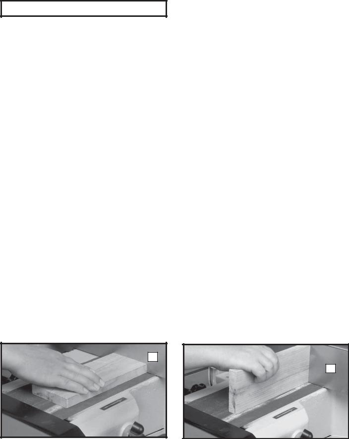
END SANDING WITH THE BELT
When you sand the ends of wide workpieces, use the sanding arm in the vertical position as shown in Fig. 60.
 Position the edge of the table a maximum of 1/16" away from the sanding belt to avoid trapping the workpiece or your fingers between the table and the sanding belt.
SANDING OUTSIDE CURVES
Sand outside curves on the sanding disc as shown in Fig. 61.
Fig. 59
Fig. 60
Fig. 61


 Sand on the left (downward) side of the sanding disc (Fig. 61). Sanding on the right (upward) side of the sanding disc could cause the workpiece to be thrown upward and could cause personal injury.


 Position the edge of the table a maximum of 1/16" away from the sanding belt to avoid trapping the workpiece or your fingers between the table and the sanding belt.
21
END SANDING WITH THE DISC
When sanding the ends of narrow workpieces, use the sanding disc as shown in Fig. 62.
 Sand on the left (downward) side of the sanding disc (Fig. 62). Sanding on the right (upward) side of the sanding disc could cause the workpiece
to be thrown upward and could cause personal Fig. 62 injury.
 You must position the edge of the table a maximum of 1/16" away from the sanding belt to avoid trapping the workpiece or your fingers between the table and the sanding belt.
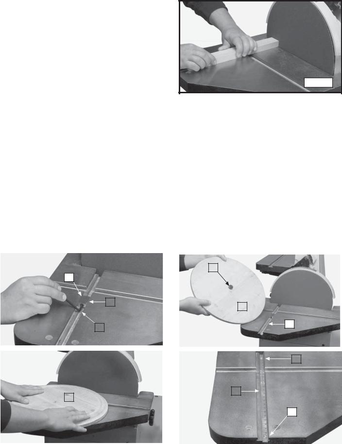
CIRCLE SANDING WITH DISC
A circle sanding attachment is supplied with the sander. It enables you to sand circles up to 24" in diameter. To use:
 Disconnect the machine from the power source!
1.Insert the stop block (A) Fig. 63 into the slot in the sanding disc table. Align the end of the outside edge (B) of the block with the diameter of the circle shown on the scale. Tighten the screw in the stop block with a 5/32" hex wrench (C) to hold the block in place.
2.Insert the guide pin (D) Fig. 64 in the center of the over-sized rough cut circle (E).
3.Insert the guide pin (D) Fig. 64 into the slot (F) of the disc sander table. Rotate the workpiece (E) Fig. 65. continuously while sanding. When the guide pin contacts the stop pin, the workpiece will be a circle of the correct size.
4.When necessary, adjust the scale (F) Fig. 66 by loosening the two screws (G), adjusting the scale in or out, and tightening the two screws.
|
|
|
|
|
|
|
|
|
|
|
|
|
|
|
|
|
|
|
|
|
|
|
|
|
|
|
|
|
|
|
|
|
|
|
|
|
|
|
|
|
D |
|
|
|
|
|
|||||
|
A |
|
|
|
|
|
|
|
|
|
|
|
|
|
|
||||||||||
|
|
|
|
|
|
|
|
|
|
|
|
|
|
|
|
|
|
|
|
|
|
|
|
|
|
|
|
|
|
|
|
B |
|
|
|
|
|
|
|
|
|
|
|
|
|
|
|
|
|
|
|
|
|
|
|
|
|
|
|
|
|
|
|
|
|
|
|
|
|
E |
|
|
|
|
|
||
|
|
|
|
|
|
|
|
|
|
|
|
|
|
|
|
|
|
|
|
|
|
||||
|
|
|
|
|
|
|
|
|
|
|
|
|
|
|
|
|
|
|
|
|
|
|
F |
||
|
|
|
|
C |
|
|
|
|
|
|
|
|
|||||||||||||
|
|
|
|
|
|
|
|
|
|
|
|
|
|
|
|
|
|
|
|
|
|
||||
|
|
|
|
|
|
|
|
|
|
|
|
|
|
|
|
|
|
|
|
|
|
|
|||
|
|
|
|
|
|
|
|
|
Fig. 63 |
|
|
|
Fig. 64 |
|
|
|
|
|
|
|
|
|
|
||
|
|
|
|
|
|
|
|
|
|
|
|
|
|
|
|
|
|
|
|
|
|
|
|
|
|
|
|
|
|
|
|
|
|
|
|
|
|
|
|
|
|
|
|
|
|
|
|
|
|
|
|
|
|
|
|
|
|
|
|
|
|
|
|
|
|
|
|
|
|
|
|
|
|
|
|
|
|
|
|
|
|
|
|
|
|
|
|
|
|
|
|
|
|
|
|
|
|
|
|
|
|
|
|
|
|
|
|
|
|
|
|
|
|
|
|
|
|
|
|
|
|
|
|
|
|
|
|
G |
|
|
|
|
|
|
|
|
|
|
|
|
|
|
|
|
|
|
|
|
|
|
|
|
|
|
|
|
|
|
|
|
|
|
|
|
|
|
|
|
|
|
|
|
|
F |
|
|
|
||||
|
E |
|
|
|
|
|
|
|
|
|
|
|
|
|
|
|
|||||||||
|
|
|
|
|
|
|
|
|
|
|
|
|
|
|
|
|
|
|
|
|
|
G |
|||
|
|
|
|
|
|
|
|
|
|
|
|
|
|
|
|
|
|
|
|
|
|
|
|||
|
|
|
|
|
|
|
|
|
|
|
|
|
|
|
|||||||||||
|
|
|
|
|
|
|
|
|
Fig. 65 |
|
|
|
|
Fig. 66 |
|
|
|
|
|
|
|
|
|
|
|
|
|
|
|
|
|
|
|
|
|
|
|
|
|
|
|
|
|
|
|
|
|
|
|
|
|
22
TROUBLESHOOTING
For assistance with your machine, visit our website at www.deltamachinery.com for a list of service centers or call the DELTA Machinery help line at 1-800-223-7278 (In Canada call 1-800-463-3582).
MAINTENANCE
REPLACING THE SANDING BELT


 Disconnect the machine from the power source!
1. |
Loosen the two lock knobs (A) Fig. 67, and remove |
|
|
|
|
|
|
|
|
|
|
|
|
|
|
|
|
||
|
the top cover (B). |
A |
|
B |
|
A |
|
|
|
2. |
Loosen the two lock knobs (C) Fig. 68 enough to |
|
|
|
|
|
|||
|
|
|
|
|
|
|
|||
|
|
|
|
|
E |
|
|||
|
allow the back panel (D) Figs. 67, 68, and 69 to |
|
|
|
|
|
|||
|
|
|
|
|
|
|
|||
|
open. |
|
|
|
|
|
|
||
NOTE: The lock knobs (C) cannot be removed.
3. |
Release the belt tension by turning the hand lever |
|
|
|
D |
|
|
|
|
|
|
||
|
(E) Fig. 67. Remove the belt (F) Fig. 69 from both |
|
|
|
|
|
|
sanding drums. |
|
|
|
|
|
4. |
Install the new sanding belt over both sanding |
|
Fig. 67 |
|
|
|
|
drums. Ensure that the belt runs in the direction of |
|
|
|
|
|
|
the arrow, printed on the inside of the belt. |
|
|
|
|
|
|
|
|
|
|
|
|
5.Turn the hand lever (E) Fig. 67 to apply tension to the sanding belt. Replace the top cover removed in STEP 2.
6.Close the back panel (D) Fig. 67. Tighten the two lock knobs (C) Fig. 68 that were loosened in STEP 3.
7.Check the belt tracking before applying power to the sander.
|
|
|
|
|
|
|
|
|
|
|
|
|
|
|
|
|
|
|
|
C |
|
|
|
|
|
|
|
|
|
||||
|
|
|
|
|
|
|
|
|
|
|
|
|||||
|
|
|
D |
|
|
|
|
|
|
|
|
|
||||
|
|
|
|
|
|
|
|
D |
|
F |
|
|||||
|
|
|
|
|
|
|
|
|
|
|
|
|
|
|
||
|
|
|
|
|
|
|
|
|
|
|
|
|
|
|||
|
C |
|
|
|
|
|
|
|
|
|
|
|
|
|||
|
|
|
|
|
|
|
Fig. 68 |
|
|
|
Fig. 69 |
|
|
|
|
|
|
|
|
|
|
|
|
|
|
|
|
|
|
|
|
|
|
REPLACING THE SANDING DISC
See the section “ABRASIVE DISC” in the “ASSEMBLY” section of this manual.
OVERLOAD PROTECTION |
|
|
|
|
|
|
|
|
|
||
The motor supplied with your sander is equipped with a |
|
A |
|
||
|
|
|
|
|
|
reset overload relay button (A) Fig. 70. If the motor shuts |
|
|
|
|
|
off or fails to start because of overloading (sanding too |
|
|
|
|
|
heavy, using a worn sanding belt or disc, using the |
|
|
|
|
|
sander beyond its capacity), or low voltage, turn the |
|
|
|
|
|
power switch to the “OFF” position. Let the motor cool |
|
|
|
|
|
three to five minutes and push the reset button (A) Fig. |
|
|
|
|
|
70. Start the motor. |
|
|
|
|
|
|
|
|
Fig. 70 |
|
|
|
|
|
|
|
|
|
|
|
|
|
|
23
 Loading...